
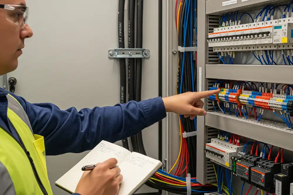
Quick Guide to Common Terminal Blocks in Industrial Automation
Choose the circuit function before the clamp style. Common automation terminals include feed-through, protective-earth (PE), multi-conductor, multi-level, disconnect, fuse, component, sensor/actuator and power-distribution blocks. Each solves a different wiring, testing or service task.
Map the panel by circuit job
A terminal strip is the service boundary between field conductors and internal panel wiring. Feed-through blocks create ordinary point-to-point paths. PE blocks serve protective conductors. Multi-conductor and multi-level designs organize common potentials or separate circuits at higher density.
Disconnect, fuse and component terminals add a defined service or circuit function. Sensor/actuator terminals organize signal and supply paths near PLC I/O, while distribution blocks fan one potential to several connections. Select the family first; then verify the exact catalog number and its complete configuration.
Keep three choices separate: function describes what the circuit must do; connection technology describes how a conductor is clamped; mounting format describes where the device is installed. “Push-in,” “DIN rail” and “fuse” are not competing labels for the same decision.
Qualified work only: this article supports planning and purchasing. Installation, testing and maintenance require the equipment instructions, the approved circuit procedure and personnel qualified for the electrical hazards involved.
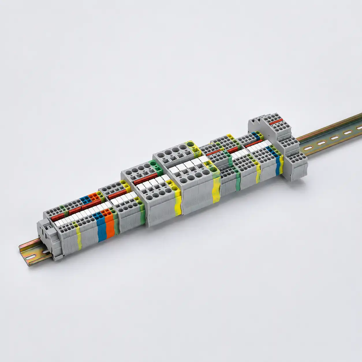
Build ordinary connections, PE paths and justified density
Start with the passive wiring paths. They establish how field conductors reach the panel and how potentials are separated or shared.
- Feed-through: typically joins conductor points through one continuous current bar. It provides connection and potential routing—not inherent disconnection, fusing or signal conditioning.
- Protective earth: connects copper protective conductors to the approved fixing support or rail path. PE, 0 V, neutral, functional earth and shield treatment are not synonyms.
- Multi-conductor: places three or more connection points on one defined potential. It does not grant permission for several wires under a clamp unless the product explicitly allows that arrangement.
- Multi-level: stacks two or more wiring levels. The exact internal diagram determines whether levels are separate, factory-bridged or configurable with accessories.
Density has a service limit. A narrow terminal strip is only useful when conductors, markers, jumpers, release points and test access remain readable and reachable after wiring.
Disconnect, fuse and component terminals change circuit behaviour
These terminals do more than join conductors. Their internal link, holder or component becomes part of the schematic, commissioning plan and maintenance record.
Create a planned break
A disconnect terminal can open a defined path without removing the field wire. It is not automatically a load-break switch, safety isolator, lockable disconnect or proof that the circuit is de-energized. Verify the exact link sequence, duty and test accessories.
Hold a specified fuse-link
The protection result depends on the fuse type or class, voltage, breaking capacity, load, holder rating, thermal conditions and coordination. Indicator electronics may add polarity, leakage or dissipation conditions in sensitive control circuits.
Document the internal function
A diode, LED, resistor or other defined component needs its circuit symbol, polarity, electrical limits, power dissipation and replacement reference. An LED is indication—not proof of absence of voltage—and a diode is not a general safety barrier.
Current-transformer exception: an ordinary disconnect terminal is not a CT test block. Never open-circuit the secondary of a conventional current-output CT while primary current may be present: hazardous secondary voltage can cause shock, burns, equipment damage or CT failure. Use only the documented shorting/test arrangement and approved equipment procedure; do not publish or improvise a generic knife-opening sequence. See Schneider Electric's CT secondary safety guidance.
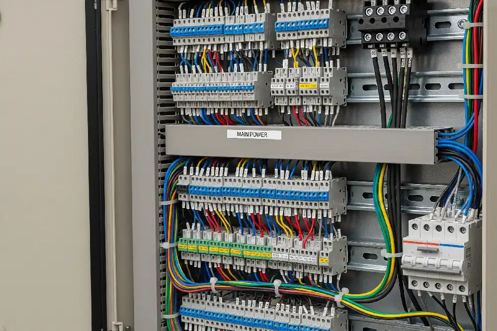
Organize signal, supply, shield and actuator paths separately
Sensor/actuator terminals compact a signal and its associated supply or common connections for field devices. They organize wiring; they are not automatically an I/O module, fuse, isolator or signal conditioner.
Power-distribution terminals fan one incoming potential to several outgoing connections. Confirm the feed position, internal commoning, incoming and outgoing wire ranges, current at each connection and total path current. Distribution adds no overcurrent protection unless the selected functional version explicitly includes it. Do not confuse this topology with a large-conductor or high-current feed-through block, which can remain a single point-to-point path. For either case, verify the fault/protection context, heat rise, touch protection, conductor-entry geometry and cabinet clearance.
Separate PE, shield and reference conductors. A shield may bond to PE, connect through another defined path or remain isolated at one end according to the system design. Terminal color alone does not decide that relationship.
Match each PLC or field-wiring need to a function
| PLC or field-wiring need | Useful terminal function | What to verify |
|---|---|---|
| Digital input | Feed-through, multi-conductor or multi-level signal terminal. | Channel label, signal/common reference, conductor data, test and isolation needs. |
| 24 V DC sensor supply | Distribution or multi-conductor terminal with a documented commoning system. | Branch current, total path, jumper/bridge rating, fuse strategy, voltage drop and polarity. |
| Analog loop commissioning | Defined disconnect or test-disconnect function where the procedure requires it. | Test-point layout, loop interruption rules, polarity, shield and reference strategy. |
| Actuator branch | Feed-through plus an engineered protective arrangement, or a suitable fuse terminal. | Load current and inrush, fuse characteristics, indication, upstream coordination and heat. |
| Cable shield / PE | Dedicated shield, functional-earth or PE solution as required by the design. | Bonding purpose, isolation, rail/support path, labeling and assembly verification. |
For a deeper I/O example, see terminal blocks for 24 V DC PLC I/O wiring. The automation and machine-control page connects the terminal strip to the wider panel BOM.
Choose the terminal function first; then choose the connection technology
Screw, spring-clamp and push-in describe how the conductor is connected. Each can support several terminal functions, but the accepted wire, preparation, stripping length, tool and inspection method belong to the exact product.
Controlled tightening
Verify the allowed conductor arrangement, preparation, strip length, tool and specified torque. A ferrule does not remove the torque requirement, and a generic torque from another family is not a substitute.
Actuated spring connection
Confirm which conductors require an actuator or tool and how insertion is checked. The spring connection has no screw-clamp torque, although mounting screws or other hardware can have their own instructions.
Defined direct-insertion range
Direct insertion can simplify repetitive work for supported conductors. The direct-insertion subset may be narrower than the general connecting capacity, especially for fine-stranded or prepared conductors.

Design the complete terminal strip
A usable rail assembly includes more than the terminal bodies. Confirm the exact rail profile, end clamps, end plates, partitions, bridges, plugs, test points, marker carriers, covers and spare ways.
- Mechanical fit: width, height, wire-entry direction, bending room, release/tool access and retained end components.
- Accessory match: part-family compatibility, pole count, jumper current path, touch protection and required separators.
- Identification: terminal numbers, field/panel side, common groups, fuse and disconnect status, PE and spare positions.
- Process control: approved tools, preparation, inspection records and change control for replacement or substitution.
Continue with the terminal-block accessories guide, or compare spring terminal blocks and screw terminal blocks within the selected function.
Consolidate the choices before opening a catalogue
This summary is a routing tool, not a rating table. Current, voltage, conductor capacity, heat, accessories and approvals belong to the exact product and installation conditions.
| Type | Best used for | Do not confuse it with | Confirm next |
|---|---|---|---|
| 1. Feed-through | Ordinary point-to-point control, signal or power paths within the declared rating. | A fuse, disconnect or PE connection. | Internal path, conductor range, current/voltage, width and bridge system. |
| 2. Protective earth | Connecting a protective conductor to the approved support or rail path. | 0 V, neutral, functional earth, shield treatment or a recolored feed-through block. | PE/PEN function, mounting, bonding, conductor conditions and assembly verification. |
| 3. Multi-conductor | Providing three or more conductor connections on one defined potential. | Permission for several wires in one clamp. | Commoned ports, wire count per clamp, total path current and bridge limits. |
| 4. Multi-level | Stacking separate or configured circuits where rail length is limited. | A guarantee that every level is common or isolated. | Internal diagram, level marking, heat, jumper paths and wire access. |
| 5. Disconnect / test | Creating a planned break or test interface for commissioning and service. | A load-break switch, isolator or proof of de-energization. | Permitted duty, procedure, circuit state, test plugs and exact link behavior. |
| 6. Fuse | Holding a specified fuse-link for a defined control or field branch. | Universal branch-circuit protection or a replacement for any breaker. | Fuse format/class, voltage, breaking capacity, heat, indicator and coordination. |
| 7. Component / diode | Adding a documented diode, LED, resistor or other defined function at the wiring level. | A generic surge protector, safety barrier or isolation device. | Circuit symbol, polarity, voltage/current, dissipation, failure mode and replacement. |
| 8. Sensor / actuator | Organizing signal and supply/common conductors for field devices near I/O. | The PLC module, automatic isolation or an undefined 0 V-to-PE link. | PNP/NPN or signal logic, commoning, indication, shield, PE and channel marking. |
| 9. Power distribution | Fanning one incoming potential to several outgoing connections. | Automatic overcurrent protection. | Feed position, line/load ranges, internal commoning, per-port and total current. |
For a category-by-category DIN-rail reference, see nine DIN-rail terminal block types and their uses. For complete model selection, continue with the terminal-block selection guide.
Turn the circuit list into a reviewable terminal-strip BOM
The workflow keeps function, wire, ratings, accessories and service needs connected. It also gives purchasing a clear basis for comparing supplier offers.
Do not begin with a favorite part number. The same panel can require ordinary feed-through paths, PE, fused branches, test points and distribution functions. One family may not cover every job.
What the seven steps should produce
- Terminal schedule
Numbered positions with circuit, potential, terminal function and field/panel-side identity.
- Complete rail BOM
Exact terminals, rail, end parts, bridges, test items, covers, markers and planned spare ways.
- Drawing and labels
Visible common groups, PE and shield treatment, fuse or disconnect state and accessory references.
- Review record
Approved models, rating evidence, assembly instructions, revisions and controlled substitution decisions.
- 01
Classify every circuit
Separate incoming or distributed power, PE, control power, digital I/O, analog I/O, actuator, shield/network, safety-related and spare circuits. Keep their potentials and protective concepts visible.
- 02
Choose the functional terminal type
Assign feed-through, PE, multi-conductor, multi-level, distribution, disconnect, fuse, component or purpose-built sensor/actuator functions from the circuit need.
- 03
Verify the exact electrical and wire data
Check conductor material, construction, size, preparation and count together with current, voltage, thermal conditions, fault/protection context and the applicable rating basis.
- 04
Choose an executable connection process
Select screw, spring or push-in only after the assembly team can apply and inspect the required strip length, ferrule rule, torque, tool or actuation method consistently.
- 05
Build the complete rail assembly
Add the exact rail, end clamps, end plates, partitions, bridges, test plugs, fuse or component plugs, markers, covers and deliberate spare positions.
- 06
Review installation and service access
Confirm cable entry, bend space, labeling, probe or release access, heat, separation and the approved procedure for measuring, disconnecting or replacing functional parts.
- 07
Release a controlled BOM and RFQ
Use exact order codes or defined equivalency criteria. Retain drawings, accessory references, approval evidence and authorization before a supplier substitutes a validated item.
Illustrative 24 V DC PLC cabinet—not a site-specific design
Map the functions
A compact machine panel may use feed-through blocks for ordinary signals, PE blocks for protective conductors, multi-level terminals for justified density, fuse terminals for selected protected branches and a controlled disconnect/test function for analog commissioning.
The schematic must define each shield relationship and common potential; color and rail location do not define them.
Preserve traceability
Separate field-side and PLC-side labels, document every bridge group, identify replaceable fuse or component parts and reserve deliberate spare ways. The goal is not simply more terminals—it is a terminal architecture that maintenance can follow.
Changing a terminal function, link or accessory is a circuit change and should follow the project’s review process.
The function determines which evidence to check
A standard defines a product scope and tests; it does not give every catalog number the same current, voltage, conductor range or finished-panel acceptance.
IEC 60947-7-1:2025
The current fourth edition covers defined support-mounted terminal blocks and Annex D test-disconnect blocks with screw or screwless clamping for round copper conductors. It does not automatically cover every PE, fuse or electronic function.
IEC 60947-7-2:2009
The official published edition addresses PE and PEN terminal blocks for copper conductors and their electrical and mechanical connection to the fixing support. Verify the exact product certification and the edition adopted by the project.
IEC 60947-7-3:2009
This safety scope concerns terminal blocks for specified IEC 60127-2 cartridge fuse-links. It does not make the holder a universal protective device or turn a standard test value into the panel’s available-fault or SCCR rating.
North American component evidence is another layer. UL 1059, sixth edition concerns terminal blocks within its scope. A UL Recognized Component is intended for integration under stated Conditions of Acceptability; it is not certification of the complete standalone panel. UL 1059 excludes field-installed power distribution blocks intended to distribute building power; those products are investigated under UL Subject 1953. Check the exact category, file, wiring, temperature and use conditions rather than treating every distribution block as a UL 1059 terminal block.
Request a complete terminal-strip configuration
Share the one-line or schematic, I/O list, conductor schedule and service requirements. SENTOP can review terminal-block directions, compatible accessories and supply organization; the responsible equipment team retains final engineering and approval decisions.
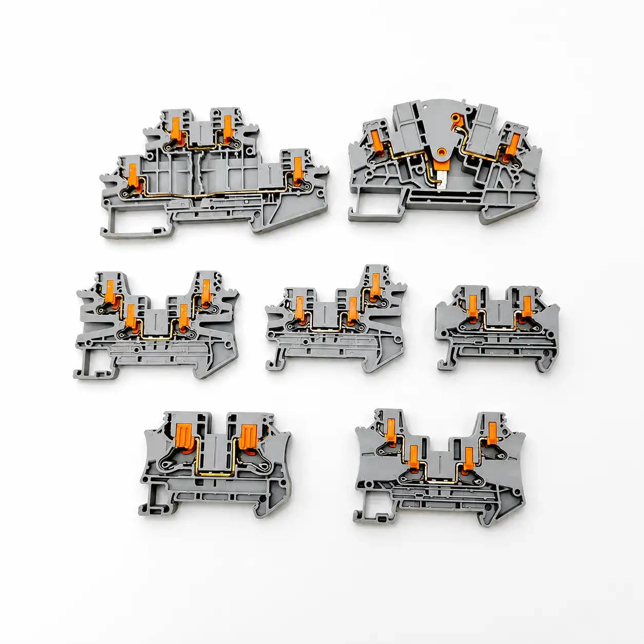
Product-family imagery does not establish an approved BOM. Image: SENTOP Electrical Co., Ltd.
Circuit and terminal role
State each potential and whether the position connects, bonds PE, distributes, disconnects, tests, fuses or contains a component.
Actual wire data
Provide material, construction, cross-section or AWG, preparation, exact stripping length, ferrule reference where relevant and permitted count per clamp.
Ratings, protection and environment
Record circuit voltage, continuous and inrush current, thermal conditions, available fault/protection context, target approval route, vibration, corrosion, pollution and cabinet environment.
Connection and tooling
Identify the preferred connection method, controlled tools, inspection approach and any service or test operation that must remain accessible.
Rail and accessories
Include rail profile, end parts, partitions, bridges, plugs, markers, covers, spare positions and available cabinet space.
Documents and change control
Request exact order codes, drawings, rating/approval evidence, sample and production quantities, labels, packing and substitution approval.
Common terminal blocks, explained clearly
Short answers for panel builders, technicians and buyers preparing an automation terminal schedule.
What is the most common terminal block in an automation panel?
Feed-through blocks are a common starting point because they create ordinary conductor-to-conductor paths at the field/panel boundary. That is not a usage statistic or a universal choice: PE, protected branches, test loops, dense I/O and distribution need their appropriate functions.
What is the difference between a feed-through and a multi-level terminal block?
A feed-through block normally provides one continuous path through a rail position. A multi-level block stacks two or more wiring levels in one housing. Check the internal circuit because levels can be separate, factory-connected or configurable with bridges.
Why is a PE terminal different from a normal terminal block?
A PE block provides the protective-conductor function and the defined connection to its approved support or rail arrangement. A gray feed-through block does not gain that function by recoloring. Verify the exact PE/PEN designation, conductor range, mounting and assembly requirements.
When should I use a fuse terminal block?
Use one when the design needs a specified fuse-link at the terminal strip for a defined control or field branch. Select the fuse and holder together with load/inrush, voltage, breaking capacity, heat, indicator behavior, upstream coordination and replacement procedure.
Can a disconnect terminal block be opened under load?
Do not assume so. The permitted action depends on the exact product rating, circuit state and approved procedure. A disconnect terminal is not automatically a load-break switch, safety isolator or proof of de-energization, and an ordinary version is not a CT shorting/test block.
Are screw and push-in terminal blocks interchangeable?
No. Either technology may suit a project, but conductor acceptance, preparation, strip length, tools, inspection and ratings are model-specific. Choose the function first, then compare products that the panel-building process can assemble and inspect consistently.
How should automation terminal blocks be labeled?
Map every position to the current drawing and identify field versus panel side, potential and bridge groups, PE, fuses, disconnect points, levels and spares. Use the compatible marker system and keep replacement or commissioning information readable after wiring.
Can I use jumpers across any adjacent terminal blocks?
No. Bridges and jumpers belong to a compatible product system and have stated pole, spacing, current-path and assembly limits. Confirm the exact part and show the commoned group on drawings and labels. Visual fit is not approval.
Source notes for scope and function
Use the exact product documents and project-adopted rules at the point of selection. Public standard pages explain scope; they do not replace the full standard or certify a pictured product.
General and test-disconnect terminal blocks
Protective-conductor terminal blocks
Fuse terminal blocks
UL component context
Functional terminal families
PLC and DCS signal marshalling
Send the I/O list, conductor schedule and drawings. Review the complete options.
SENTOP can help compare terminal-block directions, compatible accessories, model evidence and project-supply requirements before a production BOM is approved.