
The global terminal block market is projected to exceed $5 billion by 2028, and DIN rail-mounted variants account for the largest share of industrial installations worldwide. If you’re specifying components for a control panel, understanding the different DIN rail terminal block types — from basic feed-through connectors to specialized fused, sensor, and power distribution blocks — is the fastest way to build safer, code-compliant, and maintenance-friendly systems. This guide breaks down nine common types, explains exactly where each one belongs, and gives you the selection criteria that panel builders and electrical engineers actually rely on.
What Are DIN Rail Terminal Blocks and Why Do They Matter
A DIN rail terminal block is a modular electrical connector that snaps onto a standardized metal rail — typically a 35mm top-hat profile per IEC 60715 — inside control panels, junction boxes, and distribution boards. Each block provides a secure, organized connection point where two or more wires meet, replacing messy point-to-point splicing with a structured, maintainable system.
A DIN rail terminal block is a snap-on wiring connector mounted to a standardized metal rail, used to join, distribute, or switch electrical circuits inside industrial and commercial panels.
Why should you care about the specific din rail terminal block types available? Because choosing the wrong one can mean failed inspections, overheated connections, or hours of rework. A fused block protects a circuit inline; a ground block ensures NEC or IEC safety compliance; a disconnect block lets technicians isolate signals without pulling wires. Each type solves a distinct problem.
- Safety — Proper terminal selection prevents arc faults, loose connections, and ground failures.
- Density — Multi-level and pluggable blocks can cut panel space requirements by 30–50%.
- Maintenance speed — Disconnect and pluggable types reduce troubleshooting time from hours to minutes.
- Compliance — UL 1059 and IEC 60947-7-1 ratings vary by block type, directly affecting certification.
Manufacturers like Phoenix Contact, Weidmüller, WAGO, and Allen-Bradley each offer dozens of variants — screw-clamp, spring-cage, push-in — across at least nine functional categories. The sections below break down every common din rail terminal block type, explain where each one belongs, and help you avoid costly mismatches in your next panel build.
Understanding DIN Rail Standards and Sizes Before Choosing a Terminal Block
Pick the wrong rail profile, and your terminal blocks won’t even snap on. That’s why understanding DIN rail dimensions is the non-negotiable first step before evaluating any din rail terminal block types for your panel design.
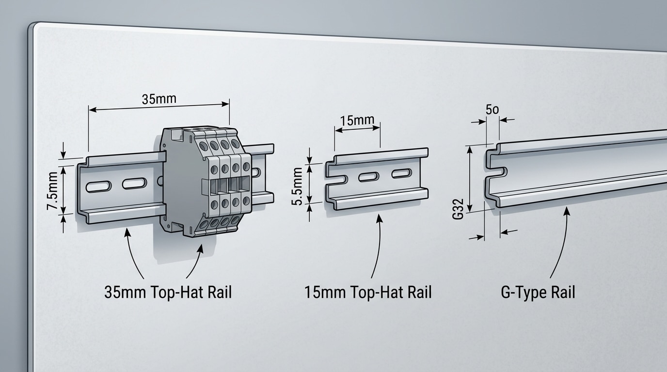
The Three Main DIN Rail Profiles
The EN 60715 standard (also referenced as IEC 60715) defines three rail profiles used globally:
| Profile | Designation | Dimensions | Typical Use |
|---|---|---|---|
| 35mm Top-Hat | TS 35 (TH 35-7.5 / TH 35-15) | 35mm wide, 7.5mm or 15mm deep | ~90% of industrial terminal blocks, PLCs, relays |
| 15mm Top-Hat | TS 15 | 15mm wide | Smaller relays, compact instrumentation |
| G-Type (G32) | G-profile | 32mm wide | Older meter panels, heavy contactors |
The 35mm top-hat rail dominates. If you’re specifying DIN rail terminal block types for a new control panel, TS 35 with 7.5mm depth is almost certainly what you need. The 15mm deep variant handles heavier components but uses the same snap-on foot geometry for most blocks.
Electrical and Safety Standards That Matter
Mechanical fit is only half the equation. Terminal blocks must also comply with IEC 60947-7-1 (the international standard for low-voltage terminal blocks) or UL 1059 for North American installations. These standards govern creepage distances, dielectric strength, current ratings, and flammability — all critical for certification.
Quick rule of thumb: if your panel ships to Europe, verify IEC 60947-7-1 compliance. Shipping to the U.S. or Canada? Demand a UL 1059 listing. Many manufacturers like Phoenix Contact, Weidmüller, and Wago hold both certifications on their major product lines.
Knowing these standards upfront prevents costly redesigns and failed inspections — especially on panels requiring NEC or CSA approval.
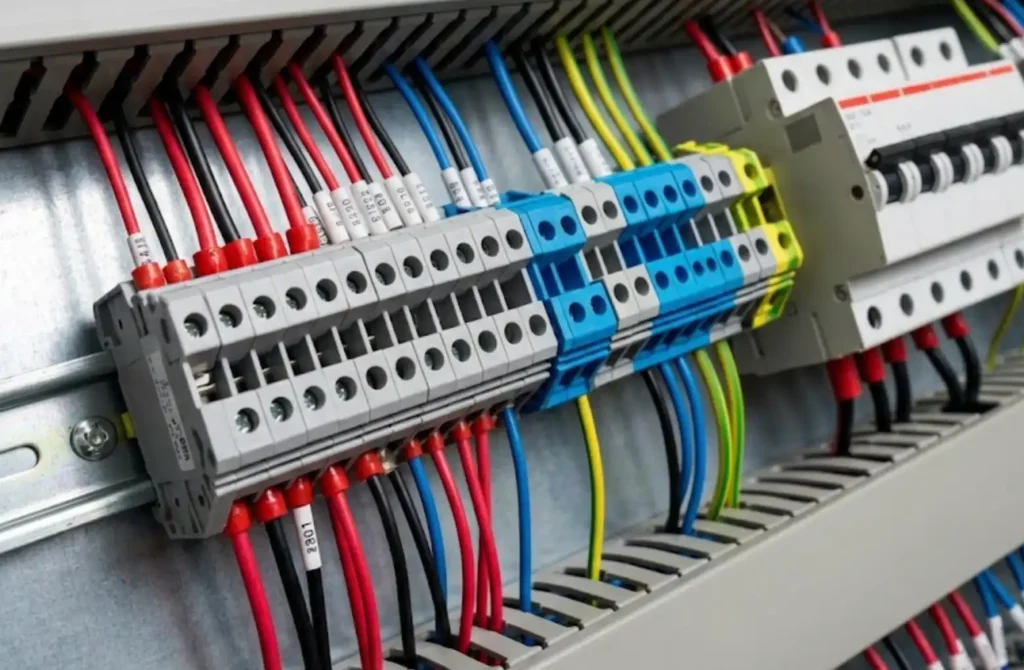
Feed-Through Terminal Blocks for Basic Point-to-Point Wiring
Feed-through terminal blocks are the workhorse of every control panel. They do one thing — connect wire A to wire B — and they do it reliably across millions of installations worldwide. If you’re surveying din rail terminal block types, this is the one you’ll encounter most often, accounting for the bulk of terminal blocks specified in industrial wiring projects.
The real choice here is connection technology. Screw-clamp terminals remain the industry default: a captive screw compresses the conductor against a metal bus bar, handling wire gauges from 26 AWG up to 4/0 AWG depending on the block size. They’re forgiving with stranded or solid wire and easy to inspect. Spring-cage (or tension-clamp) terminals from manufacturers like Weidmüller and Phoenix Contact use a stainless-steel spring to grip the conductor — no tools needed for solid wire, and vibration resistance is superior. Push-in technology takes this further: ferrule-terminated or solid conductors insert directly, cutting termination time by up to 50% according to Wago’s published benchmarks.
Rule of thumb: choose screw-clamp for legacy panels and maintenance crews familiar with torque specs. Choose push-in for new builds where speed and consistency matter more.
Typical applications include signal distribution, 24 VDC control circuits, and simple power splicing inside PLC cabinets. Voltage ratings commonly reach 600–1000 V, and current ratings range from 10 A on narrow 5 mm-wide blocks up to 150 A+ on larger frame sizes. Among all DIN rail terminal block types, feed-through blocks offer the widest selection of accessories — end plates, jumper combs, marking strips, and test plugs — making them endlessly adaptable.
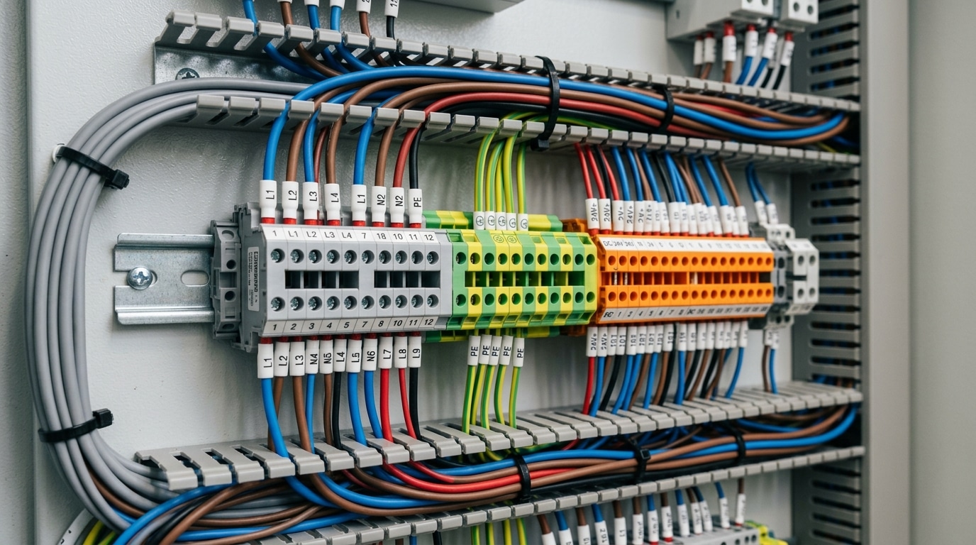
Ground and Earth Terminal Blocks for Safety Compliance
That distinctive yellow-green housing isn’t decorative — it’s mandated. Ground terminal blocks look different from standard feed-through types for a critical reason: instant visual identification of protective earth connections during installation, troubleshooting, and inspection.
The key structural difference? A ground terminal block features a direct metal foot that makes galvanic contact with the DIN rail itself. Standard feed-through blocks use plastic housings that electrically isolate the conductor from the rail. Ground blocks do the opposite — they bond the wire directly to the rail, which serves as the common grounding bus. This eliminates the need for separate ground bars in many panel designs.
Compliance Standards That Matter
Among the various din rail terminal block types, grounding blocks carry the heaviest regulatory burden. They must comply with IEC 60947-7-2 (the specific subsection for PE terminal blocks, not just the general 60947-7-1 standard). In North America, NEC Article 250 governs equipment grounding conductor terminations, requiring low-impedance paths back to the service ground.
A loose or corroded ground connection doesn’t trip a breaker — it silently waits for a fault to become lethal. Proper ground terminal blocks with verified rail contact resistance below 0.5 mΩ are non-negotiable.
- Color coding: Yellow-green per IEC 60446 / ANSI/NFPA 79 — no exceptions
- Rail contact: Serrated or spring-loaded metal foot bites through rail surface oxidation
- Cross-section range: Typically 0.5 mm² to 35 mm², matching protective conductor sizing tables
- Mounting: Can be placed anywhere on the rail — no fixed position required
Brands like Weidmüller (WPE series), Phoenix Contact (USLKG), and Wago (282 series) all offer PE ground blocks with tool-free spring-clamp or screw-clamp options. When selecting among DIN rail terminal block types for your panel, always verify that the ground block’s rated cross-section matches or exceeds your circuit’s protective conductor requirements per IEC 61439-1.
Fused Terminal Blocks for Integrated Circuit Protection
Why run a separate fuse holder and a terminal block when one device handles both? Fused terminal blocks integrate an overcurrent protection element directly into the connection point, cutting component count and saving valuable DIN rail space. Among common din rail terminal block types, these are the go-to choice for protecting sensitive instrumentation, 4–20 mA sensor loops, and low-power control circuits where a panel-mount fuse holder would be overkill.
Most fused blocks accept standard 5×20 mm glass or ceramic fuses for circuits up to about 10 A at 250 V. Heavier variants accommodate 6.3×32 mm fuses, pushing ratings closer to 15–16 A — useful for solenoid valve banks or small motor loads. Brands like Phoenix Contact (UT series), Weidmüller, and WAGO all offer models with tool-free fuse replacement via a pivoting carrier or pull-out drawer.
A blown fuse you can’t see is a blown fuse you can’t fix quickly. Look for blocks with LED or neon blown-fuse indicators — they shave minutes off troubleshooting during unplanned downtime.
Typical applications include:
- Analog sensor circuits — protecting RTDs, thermocouples, and pressure transmitters from wiring faults
- PLC input protection — isolating individual I/O channels so one short doesn’t cascade
- 24 VDC instrument power distribution — fusing each branch at 1–2 A to prevent upstream breaker trips
When specifying fused DIN rail terminal block types, match the fuse breaking capacity to your available fault current — not just the nominal load. A 5×20 mm glass fuse typically interrupts only 35–100 A, while a ceramic equivalent can handle 1,500 A or more. Choosing wrong here turns a protective device into a fire risk.
Disconnect and Knife-Switch Terminal Blocks for Test and Isolation
Imagine needing to verify a 4–20 mA loop signal in a live process control panel. Without a disconnect terminal block, you’d have to pull wires — risking arc flash, signal interruption, and wasted downtime. Disconnect (knife-switch) terminal blocks eliminate that risk entirely.
These blocks feature a removable knife blade or pivoting lever integrated between two connection points. Rotating the lever or pulling the blade opens the circuit while every wire stays firmly terminated. Technicians can then insert a multimeter or loop calibrator directly into the test points molded into the block housing. Weidmüller’s WDK series and Phoenix Contact’s UTTB disconnect blocks are among the most widely specified options, both rated for signal-level and power circuits up to 800 V depending on the model.
Why do they matter so much in process control? A single 4–20 mA instrument loop can feed a PLC analog input, a recorder, and a safety shutdown system simultaneously. Opening that loop at the wrong point kills all three functions. Disconnect terminal blocks let you isolate one segment of the loop cleanly, which is why they’re standard in petrochemical, water treatment, and pharmaceutical panels governed by ISA and IEC 61010 safety requirements.
Pro tip: When evaluating din rail terminal block types for analog loops, choose disconnect blocks with gold-plated knife contacts. Gold resists oxidation and maintains the micro-ohm contact resistance that sensitive signal circuits demand.
Among all DIN rail terminal block types used in industrial automation, disconnect blocks deliver the highest return during commissioning and maintenance — cutting loop-check time by roughly 40–60% compared to panels wired with standard feed-through blocks alone.
Multi-Level and Double-Deck Terminal Blocks for Space-Constrained Panels
Panel real estate is expensive. When enclosure dimensions are fixed but wire count keeps climbing, multi-level terminal blocks solve the problem by stacking two or three independent connection tiers within the footprint of a single standard block — often just 5.2 mm or 6.2 mm wide.
Double-deck designs from manufacturers like Phoenix Contact (DIKD series), Weidmüller (WDK series), and Wago deliver roughly 50% space savings compared to mounting equivalent feed-through blocks side by side. Triple-deck variants push that reduction even further, fitting three circuits into the width one block normally occupies on a 35 mm DIN rail.
How the Levels Work
Each level operates as an electrically independent circuit. The lower deck connects through a standard clamping mechanism at the base, while the upper deck routes conductors upward through an internal channel to a separate contact point. Cross-jumpers or bridge accessories can link levels together when you need them to share a common potential — useful for distributing a 24 VDC supply across multiple sensor circuits.
- Typical voltage rating: 500–800 V per level, depending on manufacturer and wire gauge
- Current capacity: Usually 17–24 A per tier for standard 2.5 mm² models
- Marking: Color-coded tiers and individual labeling strips prevent cross-wiring errors
Among the various din rail terminal block types, multi-level blocks demand the most careful planning during panel layout. Routing upper-level wires requires slightly more vertical clearance, and technicians need clear labeling to trace circuits during maintenance. Skip the labeling step, and troubleshooting a packed panel becomes a nightmare.
Pro tip: When specifying double-deck blocks, verify that your wire ferrule length matches the upper-deck insertion depth. Some blocks require longer ferrules for the top tier — a detail often missed until assembly day.
Sensor and Actuator Terminal Blocks for Field Device Wiring
Every proximity sensor, solenoid valve, or PT100 transducer needs at least three connections: power supply, signal return, and ground. Running each of those through separate feed-through blocks wastes rail space and invites wiring mistakes. Sensor and actuator terminal blocks solve this by stacking three or four conductors into a single compact housing — typically no wider than 6.2 mm per pole.
What makes these blocks immediately recognizable? Color-coded levels. A common configuration from manufacturers like Weidmüller (the TERM series) or Phoenix Contact (the PTIO line) uses a blue level for the negative/ground rail, a white or gray level for the signal conductor, and a red level for the 24 V DC supply. This visual coding slashes miswiring rates during field device hookup, which is critical when a panel has 60+ sensor connections.
Among all din rail terminal block types, sensor blocks deliver the highest connection density per millimeter of rail — consolidating what would otherwise require three separate blocks into one.
Three-conductor variants handle standard NPN/PNP sensors and two-wire actuators. Four-conductor versions add a dedicated PE (protective earth) level, which is essential for shielded cables on analog transducers carrying 4–20 mA or 0–10 V signals. The fourth level also satisfies EMC requirements in environments governed by IEC 61131-2 for programmable controller installations.
One practical tip: match the terminal block’s rated cross-section to your field cable gauge. Most sensor blocks accept 0.14–1.5 mm² conductors via push-in or tension-spring connections — perfectly sized for the 0.34 mm² or 0.75 mm² cables common in sensor runs. Oversizing here just makes termination harder without any electrical benefit.
If you’re designing panels with dozens of field devices, these specialized DIN rail terminal block types cut wiring time significantly and produce a cleaner, more maintainable layout than any combination of standard single-level blocks.
Power Distribution Terminal Blocks for High-Current Applications
Standard screw-clamp terminal blocks top out around 30–50 A. That’s nowhere near enough for main power feeds entering a panel at 100 A, 200 A, or beyond. Power distribution terminal blocks fill this gap with bolt-type or stud connections engineered for large-gauge conductors — typically 4 AWG up to 350 kcmil (185 mm²).
These blocks function as the first point of contact inside an enclosure, replacing traditional bus bars in many designs. A single high-current block can accept the incoming supply conductor on one side and distribute power to multiple downstream branches through integrated bus-bar jumpers or cross-connection systems. Weidmüller’s WPD series and Phoenix Contact’s PTPOWER line are two widely specified options, with some models rated above 232 A at 1,000 V.
Rule of thumb: if your incoming conductor exceeds 6 AWG (16 mm²), skip standard feed-through blocks entirely and specify a dedicated power distribution type.
Key Features That Set Them Apart
- Bolt/stud termination: M6, M8, or M10 studs deliver the contact pressure needed for low-resistance, high-amperage joints — far superior to spring or screw clamps at these ratings.
- Wider housing footprint: Bodies are 25–55 mm wide to accommodate creepage and clearance distances required by IEC 61439 and UL 508A.
- Color-coded phases: L1 (brown), L2 (black), L3 (grey), and N (blue) housings simplify three-phase distribution at a glance.
- Touch-safe design: IP20-rated finger protection prevents accidental contact with live conductors during maintenance.
Among all din rail terminal block types, power distribution blocks demand the most attention to torque specifications. Under-torqued bolts cause hot spots; over-torqued bolts crack the housing. Always use a calibrated torque wrench — not a standard screwdriver — and follow the manufacturer’s Nm rating printed on the block.
These blocks mount on standard 35 mm top-hat DIN rails (EN 60715), though heavier models may require additional rail supports spaced no more than 200 mm apart to prevent rail deflection under the weight of large cables.
Pluggable and Connector-Style Terminal Blocks for Modular Systems
What if you could disconnect an entire wire harness — 20, 30, even 50 conductors — in under five seconds, with zero tools? That’s exactly what pluggable terminal blocks deliver. They split a standard terminal point into a male base that stays mounted on the DIN rail and a female plug that carries the field wiring. Pull the plug, and the whole sub-assembly lifts away cleanly.
This design is transformative for modular machine building. OEMs like Beckhoff and Siemens rely on plug-in interfaces so pre-wired panel sections can be tested on a bench, shipped separately, and snapped together on-site in minutes. Downtime during equipment swaps drops from hours to the length of a coffee break.
Where Pluggable Blocks Shine
- Pre-wired sub-panels: Factory-terminated harnesses eliminate field wiring errors and cut commissioning time by up to 60%.
- Rapid equipment swaps: A failed drive module or PLC rack can be replaced without re-terminating a single conductor.
- Standardized machine variants: The same base panel accepts different plug configurations for regional or customer-specific options.
Among the various din rail terminal block types, pluggable variants typically use spring-cage or push-in contacts rated from 2.5 mm² to 16 mm², covering signal-level and moderate power circuits alike. Phoenix Contact’s COMBICON and Weidmüller’s OMNIMATE series are two widely specified product families, both carrying UL and IEC 61984 approvals for industrial connector interfaces.
One caveat: pluggable connections add 3–5 mm of width per pole compared to fixed equivalents. In tight enclosures, verify your rail space budget before committing to a full plug-in architecture.
For any panel designed around modularity — whether packaging lines, test rigs, or data-center power distribution — connector-style DIN rail terminal blocks eliminate the single biggest bottleneck: re-wiring.
Diode, LED, and Component-Carrier Terminal Blocks for Signal Conditioning
Some wiring problems don’t need a separate module — they need smarter terminals. Component-carrier terminal blocks embed discrete electronic parts directly inside the housing: diodes for flyback suppression, LEDs for status indication, resistors for signal attenuation, or varistors and TVS diodes for surge protection. The result is in-line signal conditioning without extra board space or loose components rattling around the panel.
How They Work
A removable plug or cartridge sits between the two clamping points. Current passes through the integrated component before reaching the outgoing conductor. Weidmüller’s WSI series and Phoenix Contact’s ST-SI family both use this cartridge approach, letting technicians swap a 1N4007 diode module for an LED module in seconds — no rewiring required.
A single diode terminal block across a 24 V DC relay coil clamps inductive kickback voltage from potentially hundreds of volts down to roughly 0.7 V above supply, protecting PLC outputs that typically tolerate no more than 30 V.
Common Configurations
- Diode modules: Flyback/freewheeling protection for relay and solenoid coils
- LED modules (typically 24 V DC): Instant visual confirmation that a circuit is energized — invaluable during commissioning
- Resistor modules: End-of-line supervision resistors for fire alarm and security loops
- Varistor/TVS modules: Transient voltage suppression rated up to 600 V for field-facing I/O
Among all din rail terminal block types, component-carrier variants are the most underused — yet they eliminate failure points by removing hand-soldered components from terminal strips. If you’re designing panels with dozens of relay outputs, specifying diode terminal blocks from the start saves hours of troubleshooting later.
How to Select the Right DIN Rail Terminal Block Type for Your Project
Start with three non-negotiable specs: maximum voltage, maximum current, and wire gauge range. A 600 V rated block running on a 1,000 V DC solar string isn’t just undersized — it’s a fire risk. Check the UL and IEC ratings independently, because they often differ for the same product.
Connection technology matters more than most engineers admit. Spring-cage and push-in designs cut installation time by 50–70% compared to screw clamp, according to Weidmüller’s own field studies. But screw terminals still dominate in high-vibration environments like marine or rail transport panels where spring fatigue is a concern.
Environmental conditions narrow your choices fast. Outdoor enclosures in chemical plants demand blocks rated to at least IP20 with halogen-free housings and operating ranges from −40 °C to +105 °C. For hazardous locations, look for ATEX or IECEx certification — standard UL 1059 or IEC 60947-7-1 approval alone won’t suffice.
Use this comparison table to match all nine din rail terminal block types against your project requirements:
| Type | Typical Voltage | Current Range | Wire Gauge (AWG) | Best For |
|---|---|---|---|---|
| Feed-Through | 600–1,000 V | 6–115 A | 26–2 | General point-to-point wiring |
| Ground / Earth | N/A (PE) | 6–115 A | 26–2 | Safety grounding, bonding |
| Fused | 250–600 V | 0.5–15 A | 26–12 | Instrument circuit protection |
| Disconnect / Knife | 400–800 V | 4–20 A | 26–10 | Loop testing, isolation |
| Multi-Level | 400–800 V | 6–32 A | 26–10 | Space-constrained panels |
| Sensor / Actuator | 24–250 V | 2–16 A | 26–14 | 3- or 4-wire field devices |
| Power Distribution | 600–1,000 V | 100–350 A | 8–350 MCM | Main power feeds, busbars |
| Pluggable / Connector | 300–600 V | 6–32 A | 26–8 | Modular machine builds |
| Component Carrier (Diode/LED) | 24–250 V | 1–10 A | 26–14 | Signal conditioning, indication |
One final filter: certification scope. UL Listed blocks satisfy North American inspectors, while CE-marked blocks with IEC 60947-7-1 compliance cover European and most international markets. Projects shipping globally should specify blocks carrying both — Phoenix Contact, Wago, and Weidmüller all offer dual-certified lines across every major din rail terminal block type.
Frequently Asked Questions About DIN Rail Terminal Block Types
What’s the difference between screw-clamp and push-in connections?
Screw-clamp terminals use a tightened screw to compress the conductor against a metal plate — reliable, but installation takes roughly 3× longer per connection. Push-in (or spring-cage) terminals accept solid or ferrule-tipped stranded wire with a simple insertion, no tools required. Push-in types also resist vibration loosening better because the spring maintains constant pressure. For high-vibration environments like mobile equipment or shipboard panels, push-in connections from manufacturers like Weidmüller or Phoenix Contact are the stronger choice.
Can you mix different din rail terminal block types on the same rail?
Absolutely — and most real-world panels do exactly that. Feed-through, ground, fused, and disconnect blocks from the same product family share identical mounting feet and snap onto a standard 35 mm DIN rail side by side. Just keep ground blocks grouped together and use end brackets to prevent lateral sliding. Mixing families across manufacturers can cause fitment gaps, so stick to one brand per rail section when possible.
How should terminal blocks be labeled?
Use the marker strips or tag holders designed for your specific block series. Print wire numbers that match your schematic — IEC 60446 color coding for ground and neutral, sequential numbering for everything else. Thermal-transfer printed markers outlast handwritten labels by years in industrial settings.
Which types handle vibration best?
Spring-cage and push-in din rail terminal block types outperform screw-clamp variants under sustained vibration. IEC 60068-2-6 testing confirms that spring connections maintain contact integrity at frequencies up to 150 Hz, whereas screw terminals can loosen over time without periodic retorquing.
Choosing the Right Terminal Block Makes Every Panel Safer and More Efficient
A mismatched terminal block doesn’t just create an inconvenience — it introduces a failure point. Undersized current ratings cause heat buildup. Missing disconnect blocks turn routine loop checks into full-panel shutdowns. Skipping dedicated ground terminals risks non-compliance with IEC 60947-7-1 and, worse, puts technicians in danger.
The nine DIN rail terminal block types covered here aren’t interchangeable options on a spec sheet. Each one solves a specific electrical and mechanical problem. Treating them as commodities — grabbing whatever feed-through block is cheapest — costs more in rework, downtime, and safety incidents than the price difference ever saved.
Audit your existing panels with one question per terminal: Does this block match the voltage class, current demand, and maintenance workflow of the circuit it serves? If the answer is uncertain for even 10% of your connections, you have a redesign opportunity that pays for itself.
Manufacturers like Phoenix Contact, Weidmüller, and Wago all offer free online selection tools that filter by wire gauge, function, and approval standard. Use them. Cross-reference results against your panel layout drawings before ordering. Five minutes of configuration software beats five hours of field troubleshooting.
Whether you’re specifying a new build or inheriting a legacy system, understanding the full range of din rail terminal block t
See also
What should you know about DIN rail circuit breakers for home and industry
What is a DIN rail mounted miniature circuit breaker and how does it work
Features and Functions of DIN Rail Mount Terminal Blocks Explained
Wholesale PT 2.5 Spring Din Rail Terminal Block

Discover more from SENTOP Electrical Co., Ltd
Subscribe to get the latest posts sent to your email.
