
Features and Functions of DIN Rail Mount Terminal Blocks Explained
DIN rail mount terminal blocks create a modular, identified interface between field conductors and internal panel wiring. The base function is conductor-to-conductor termination; coordinated variants can also distribute potentials, connect protective earth, hold supplemental fuses, provide disconnect or test access, accept pluggable interfaces, terminate shields and carry circuit identification.
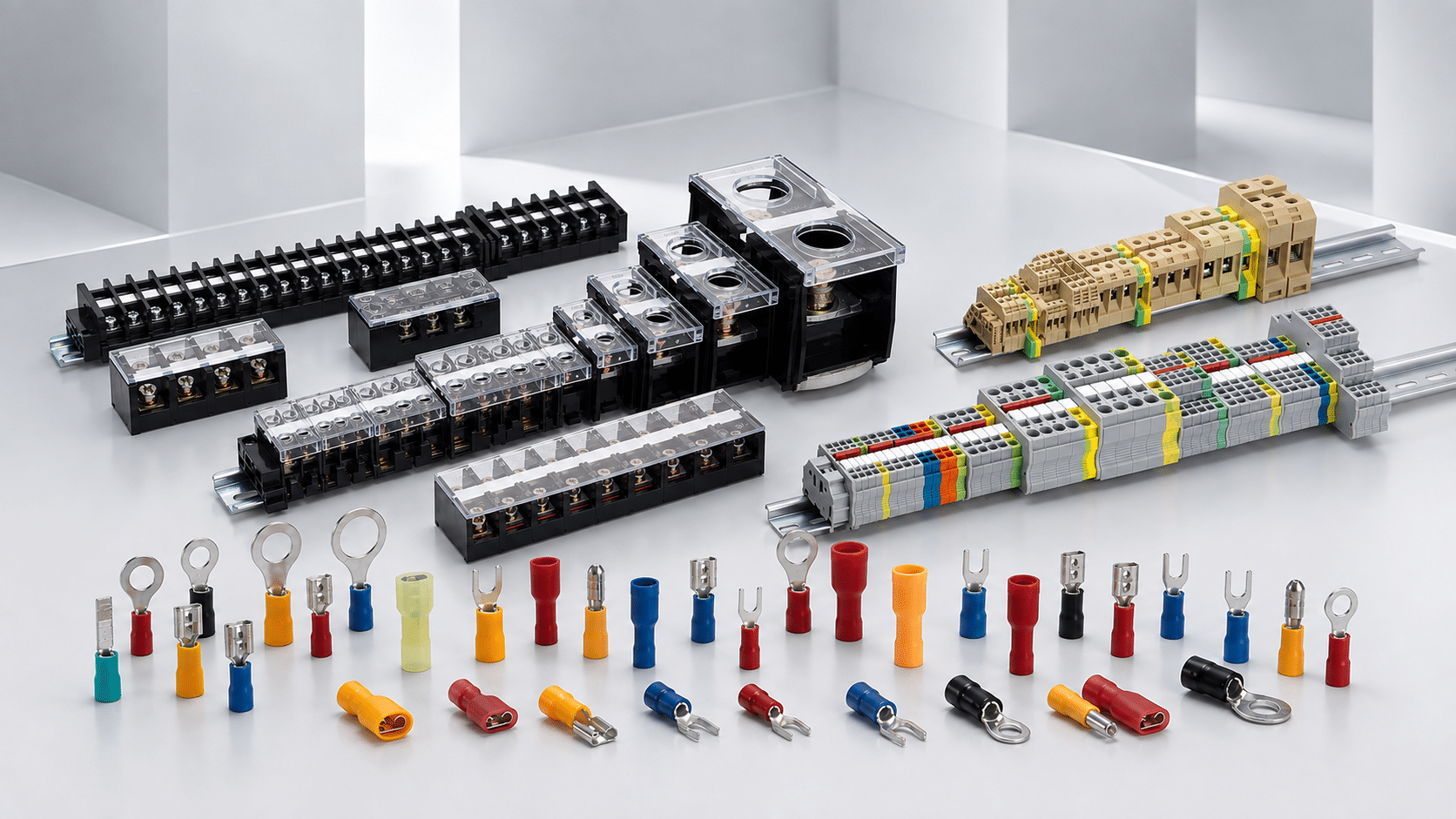
SENTOP first-party product-family image. The montage illustrates terminal formats; exact functions, ratings, rail interfaces and accessories depend on the selected model and current documentation.
What do DIN rail mount terminal blocks actually do?
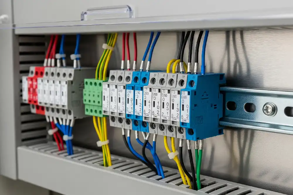
A DIN rail mount terminal block is a modular connection component fixed to a compatible mounting rail. In a typical control panel, one side receives field wiring and the other side connects to internal devices or panel conductors. A row of blocks becomes a terminal strip with controlled positions, potentials, functions and labels.
The most important feature is not simply “snaps onto DIN rail.” It is the ability to build a repeatable wiring interface from coordinated parts. Feed-through blocks connect conductors. Dedicated variants add protective-earth (PE), fusing, disconnect/test, multi-level, pluggable, shield or component functions. Jumpers distribute a potential; markers connect physical positions to drawings; end hardware retains and closes the row.
Select the function first, then verify the exact voltage/current data, conductor matrix, connection method, rail, dimensions, environmental limits, approvals and compatible accessories. Physical fit does not prove electrical suitability.
Safety boundary: this page explains selection and architecture. Installation, inspection, testing and changes inside electrical equipment must follow approved drawings, product instructions, applicable standards and the site's qualified-person and de-energization process.
What “DIN rail mount” really means
IEC 60715 defines dimensional and functional requirements for compatible mounting of switchgear, controlgear and accessories on specified rail types. Its role is mechanical compatibility. The standard explicitly leaves any protective-earthing function of the rail to the relevant product standard.
The familiar 35 mm top-hat rail is common, but “DIN rail” is not one universal interface. Rail profile, depth, material, mounting orientation, end restraint and the terminal's rail foot must match. The strip also needs room for wire entry, bend radius, duct covers, markers, tools and future service.
IEC 60947-7-1:2025 covers terminal blocks and Annex D test-disconnect terminal blocks with screw or screwless clamping units within its stated copper-conductor and voltage scope. Those scope limits are not the rating of every product. Use the exact product data.
- Rail
- Standardized mechanical support for compatible devices. It carries current or PE only when the relevant product and assembly design define that function.
- Terminal block
- A device with one or more clamping units that makes declared electrical and mechanical conductor connections.
- Terminal strip
- The assembled row: functional terminals, rail, end restraint, end plates, partitions, jumpers, markers, test items and reserved positions.
- Terminal schedule
- The controlled record linking each physical position to potential, function, wire number, conductor, destination, accessories and part number.
Eight common terminal-block roles
These roles can share a family and mounting system, but they are not interchangeable. Each one changes what must be checked and documented.
Feed-through connection
Joins declared conductors at one potential, commonly between field and panel wiring. Verify voltage, current, conductor construction, preparation and connections per clamping point.
Potential distribution
Uses multi-conductor blocks or approved jumpers to common selected positions. The bridge pattern and accessory rating must remain attached to the strip drawing.
Protective earth
Provides a declared PE connection between copper conductors and the fixing support. IEC 60947-7-2 addresses this distinct protective function; an ordinary feed-through block is not a substitute.
Multi-level wiring
Places multiple isolated or intentionally bridged levels in one footprint. It can save rail length, but level marking, separation and jumper topology must be unambiguous.
Fuse function
Accepts a specified fuse in a terminal format. UL describes fuse terminal blocks as supplemental protection for components or internal circuits, not universal branch-circuit protection.
Disconnect and test
Creates a designed separation or access point for the declared circuit. Verify switching/isolation duty, test accessories, visible status and the approved procedure before operation.
Pluggable interface
Separates fixed wiring from a removable plug for modular assembly or service. Coding, mating family, touch protection, current-carrying curve and removal state are product-specific.
Shield and components
Special modules may terminate cable shields or carry diodes, LEDs and other defined components. Keep signal reference, protective earth and shield strategy distinct in the design.
A function name is only the starting point. “Fuse terminal,” “PE terminal” or “test terminal” does not define the complete application. The exact device, conductor, rail, accessory, protective-device context and intended market still control.
How the clamping method changes wiring and service
Actuation style affects conductor preparation, tools, inspection and access. It does not replace the exact conductor table or installation instructions.
| Connection method | How it is operated | Where it can fit | What must be verified |
|---|---|---|---|
| Screw clamp | A screw applies the specified clamping force through the terminal mechanism. | Established panel processes, broad product families and applications where controlled tightening is practical. | Conductor form, strip length, driver, torque, ferrule permission, accessibility and inspection policy. |
| Spring clamp with operating slot | A tool opens the spring; some designs hold the clamping point open during termination. | Dense rows and repeatable wiring where a spring connection and tool-actuated opening suit the process. | Approved tool, insertion depth, conductor preparation and how removal is performed without damaging the terminal. |
| Direct push-in | Eligible rigid conductors or fine-stranded conductors with permitted ferrules can be inserted directly in specific products. | High-volume panel assembly and compact wiring where the actual conductor set is compatible. | Which conductors support direct insertion, ferrule type, strip length, release method and the exact data row—not a generic “tool-free” claim. |
| Lever or push-button variant | A lever or push-button actuates a spring-based clamping point; the visible interface can simplify opening and rewiring. | Field-facing connections, frequent changes or mixed conductor handling when the selected model permits it. | Open/closed indication, tool or hand operation, conductor matrix, space for actuation and shared accessories within the declared family. |
“Tool-free” never means “inspection-free.” Check conductor material, solid/stranded/flexible construction, bare or ferruled preparation, sleeve dimensions, strip length, insertion depth and the number of conductors permitted in each clamping point.
Accessories that make the row work as designed
Terminal accessories are functional BOM items. Some manufacturers standardize selected items across a defined system; other accessories remain model- or pitch-specific.
End clamps
Restrain the assembled row against wiring forces. Match rail profile, terminal family and mounting direction.
End plates
Close exposed sides where the product design requires insulation or physical completion of the terminal row.
Jumpers
Common adjacent, staggered, step-down, vertical or remote points. Verify exact pitch, slot, pole pattern and current/voltage data.
Markers
Link physical positions to schematics and test records. Freeze marker profile, source data, orientation and print method.
Partitions
Add declared separation or a clear visual boundary between functions or potentials where the design requires it.
Test accessories
Provide compatible, identified access for the approved measurement or commissioning plan instead of improvised probes.
Coding and plugs
Control mating and replacement in pluggable or function-terminal systems. Define what remains energized when a plug is removed.
Shield hardware
Connect cable shields to the declared reference or support as part of the equipment's electromagnetic-compatibility design.
Do not approve an accessory by appearance. Matching width, color or apparent fit does not prove mechanical engagement, electrical rating, touch protection or compatibility with the base terminal.
Ratings and conditions that must stay together
A usable specification links each number to the exact product, conductor, accessory, environment and evaluation context.
| Data item | Why it changes the choice | Minimum release question |
|---|---|---|
| Voltage and insulation data | Clearance, creepage, impulse withstand, material group and pollution degree influence insulation coordination. | Does the exact part and assembled arrangement cover the project's circuit and environmental conditions? |
| Current and temperature rise | Published tests use defined conductors, current and mounting arrangements; adjacent devices and cabinet temperature change the application. | Which declared current applies with the actual conductor, jumpers, grouping, ambient and neighboring heat sources? |
| Conductor matrix | Rigid, stranded, flexible, bare, ferruled, copper and permitted aluminum cases can have different ranges. | Does every project conductor match an explicit row for material, construction, preparation and quantity per clamp? |
| Fault-current context | IEC short-time withstand current, North American short-circuit current rating (SCCR) and an overcurrent device's interrupting rating are different concepts. | What component and panel evaluation method applies, and which exact overcurrent protective device (OCPD), voltage, conductor and installation conditions are required? |
| Approvals and market | A certificate, listing or recognition can cover only specified catalog numbers, ratings and conditions of acceptability. | Does the evidence identify the ordered part and intended equipment, jurisdiction and use condition? |
| Environment and mechanics | Temperature, altitude, vibration, contamination, corrosion, orientation, enclosure ingress and service access can change the design. | Do product instructions and the panel assessment cover the actual site rather than a benign catalog assumption? |
No universal margin replaces engineering data. Do not select every terminal at “1.5 times load current” or copy the largest family rating. Use the applicable project standard, circuit calculation, product data, thermal review and protective-device coordination.
The assembly can be limited by a smaller part. A jumper, fuse holder, plug, conductor, partition or adjacent spacing requirement may control the usable row even when the base terminal headline is higher.
Six steps to lay out a serviceable terminal strip
The strip should be planned from the wiring diagram, not assembled from leftover blocks at the end of the panel design.
Map every circuit position
Identify incoming power, PE, safety circuits, analog signals, digital I/O, communications and outgoing field wiring. Give each position a potential, function, wire number and destination.
Choose functions and conductor interfaces
Select feed-through, PE, fuse, disconnect/test, multi-level, plug, component or shield roles. Attach the actual conductor material, size, construction and preparation.
Build potential and separation logic
Define jumper groups, voltage-system boundaries, level-to-level relationships, partitions, shield references and any required physical spacing. Do not rely on color alone.
Place rail and service space
Freeze rail type and length, end restraint, terminal orientation, wiring-duct clearance, bend space, marker visibility and tool/test access after neighboring devices are installed.
Release the complete BOM and schedule
Include exact terminals, rail, end clamps, end plates, jumpers, markers, partitions, covers, plugs, test items, spare ways and the controlled numbering file.
Inspect the built row against the release
Verify part numbers, position sequence, jumper pattern, markers, conductor preparation, connection method, end restraint and PE continuity where applicable using the approved inspection plan.
Six common ways a terminal row goes wrong
Most problems come from a mismatch between product data, conductor preparation, accessories, layout and the released documentation.
Wrong screw process
Incorrect driver, torque, strip length or conductor preparation can compromise the connection. Prevent it with exact work instructions, approved tools and the required inspection record.
Incomplete spring insertion
A conductor can look present without being fully seated. Use the permitted conductor/ferrule combination, strip length, actuation method and visual confirmation defined for the product.
Wrong potential bridging
An incorrect jumper, level or slot can common circuits unintentionally. Control it with the terminal drawing, bridge order code, position markers and continuity verification.
Thermal mismatch
Undersized conductors or bridges, loose connections and nearby heat sources can reduce margin. Review the actual row, enclosure and manufacturer conditions together.
Poor service access
A dense row can hide labels and block probes or release tools. Check the as-built geometry with wiring ducts, neighboring devices and connected conductors in place.
Ground/shield confusion
Protective earth, circuit common, functional ground and cable shield are not automatically the same node. Give each a declared role in the grounding and EMC design.
Design service features before commissioning
Testing is easier when the access point, isolation state, compatible accessory and retained evidence are part of the terminal plan.
Defined access
Provide test sockets, compatible adapters or purpose-designed disconnect points where the test plan expects them. An exposed conductor is not an equivalent test point.
Visible identification
Keep terminal, potential and wire markers readable after wiring. Match the physical row to the schematic, wire list and commissioning record.
Known removal state
For plugs, fuses or disconnects, document what remains energized, what is interrupted, which coding applies and whether the circuit is permitted to open.
Product-specific maintenance
Inspect restraint, covers, markers, conductors and evidence of heat. Follow manufacturer/site rules rather than a universal retorque interval or generic pull test.
Six records to send with a terminal-strip enquiry
The same information should support quotation comparison, engineering release, purchasing and incoming inspection.
Record AC/DC, voltage/current context, circuit function, destination, conductor material, cross-section/AWG, construction, preparation and number per clamping point.
State rail profile and length, orientation, available cabinet space, wiring-duct access, bend space, environment and planned spare capacity.
Identify every feed-through, PE, fuse, disconnect/test, multi-level, pluggable, component, shield and distribution position.
List end hardware, jumpers, partitions, covers, markers, test plugs, coding pieces, tools and the controlled terminal-number file.
Provide target market, applicable panel standard, certification/listing needs, temperature, altitude, pollution/environment and relevant builder requirements.
Request the terminal schedule, BOM, data sheets, compatible-product evidence, connection instructions, drawings, revision record and service-spares list.
Select a coordinated family, not isolated look-alikes. A compatible family can align mounting dimensions, marker positions, jumper interfaces, end hardware and documentation—while still allowing different sizes and functional blocks where the design requires them.
DIN rail mount terminal blocks: FAQ
What is the main purpose of a DIN rail terminal block?
Its main purpose is to provide a modular, identified conductor connection inside electrical equipment. A row creates an organized interface between field and panel wiring; dedicated variants can add PE, fusing, disconnection, testing, distribution, indication, shielding or pluggability.
Are DIN rail terminal blocks interchangeable?
No. Blocks, rail feet, jumpers, markers, end plates and function modules can be specific to a series, pitch and rating. Compare exact order codes, conductor data, dimensions, approvals and official compatible-product records.
Do DIN rail terminal strips need end clamps?
The assembled row normally needs the specified end restraint so blocks do not move under wiring or service forces. Use the end clamps and end hardware declared for the selected rail and terminal system.
Does the DIN rail automatically provide protective earth?
No. IEC 60715 treats the rail as mechanical support and leaves any PE function to the relevant product standard. Use a dedicated PE terminal and the declared terminal-to-rail and bonding arrangement for the design.
How do I choose between screw, spring and push-in terminals?
Compare the actual conductor types, preparation, current/voltage data, tools, assembly process, access, environment and service method. Each technology can work well when the exact product and wiring process match the application.
What are jumper bars used for?
Jumpers intentionally common selected terminals to distribute a potential. Select them by the exact terminal system, pitch, slot, pole pattern, current/voltage data and the required commoning topology.
When should I use fuse or disconnect terminals?
Use them when the circuit design needs the exact supplemental fuse, disconnect or test function and the device is rated for that duty. They do not replace required branch protection, disconnecting means or qualified live-work procedures.
Can a terminal block be reused in another panel?
Do not assume reuse from appearance alone. Follow the manufacturer and project rules for removal, inspection and permitted reuse, and reject parts with damage, heat evidence, deformation, compromised clamping parts or uncertain traceability.
Standards and official technical sources
These references establish scope and examples. Current documentation for the exact selected terminal and finished equipment remains controlling.
- IEC 60715:2017 — standardized mounting on rails
- IEC 60947-7-1:2025 — terminal blocks for copper conductors
- IEC 60947-7-2:2009 — protective-conductor terminal blocks
- UL Solutions — connector and terminal-block certification services
- UL Solutions — UL 508A Supplement SA component context
- WAGO — rail-mount terminal block functions and variants
- WAGO — lever, push-button and operating-slot variants
- Phoenix Contact — feed-through, multi-conductor and multi-level terminal blocks
- Weidmüller — electrical testing of terminal blocks
Match the terminal function to your panel and conductor schedule
Send SENTOP the circuit list, conductor data, target market, rail/enclosure conditions, required functions and quantities. We can review a coordinated terminal family, accessories and documentation package for quotation.