
Fine-Stranded Wire in Push-In Terminal Blocks
Fine-stranded wire is suitable only when the exact terminal documentation approves the conductor construction, size, end preparation, and connection mode. “Accepted by the clamp,” “tool-free direct insertion,” and “accepted with a ferrule” are separate claims. The word push-in does not prove all three.
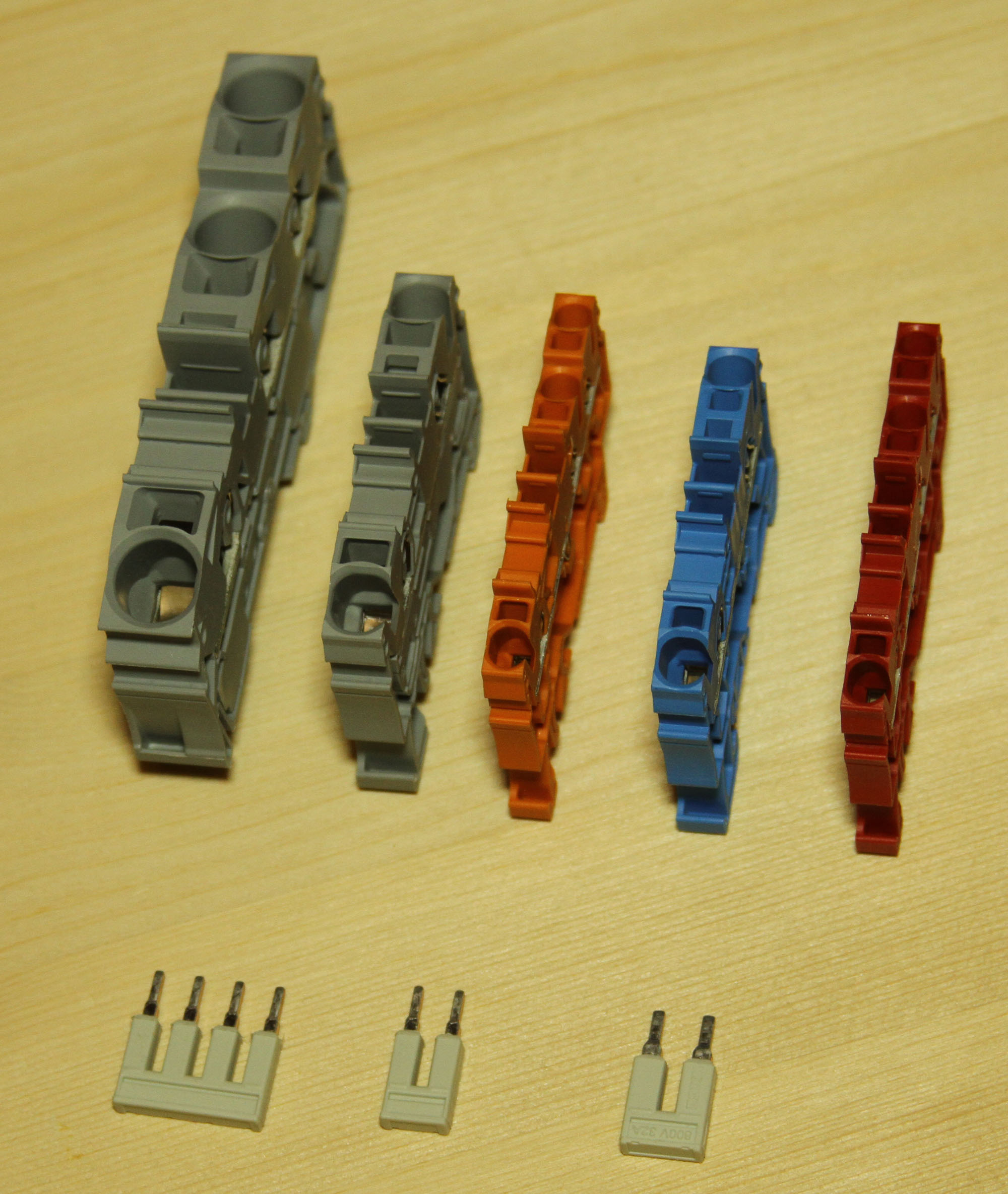
Illustrative terminal-family photo only. Photo: Zimin.V.G. / Wikimedia Commons, CC BY-SA 4.0; cropped and darkened for this page. The image does not establish conductor compatibility for every pictured terminal.
Ask what this exact terminal permits
Do not ask only whether a product is called push-in. Release the connection only when all four gates are supported by current part-number-level evidence.
Identify the conductor
Confirm manufacturer, copper material, actual AWG or mm², strand construction or documented IEC class, insulation, and whether the end is bare, ferruled, bonded, welded, or pin-terminated.
Identify the connection mode
Determine whether that prepared end may be inserted directly or must be connected by operating a pusher, push-button, lever, tool slot, or other documented spring-opening method.
Match the terminal data row
Use the exact model’s minimum and maximum range for that conductor form, including collar or sleeve details, direct-insertion limits, and the number of conductors per clamping point.
Preserve the approved system
Confirm strip length, ferrule/tool system where used, bridge and feed-in ratings, electrical duty, environment, certification conditions, and end-product documentation.
Explicitly documented
The exact construction, size, preparation, conductor count, and connection mode appear in current manufacturer data. Release through normal engineering and production controls.
One fact is unclear
A value comes from a related family, distributor summary, old revision, or general technology page. Pause and obtain exact manufacturer or engineering evidence.
Based on fit or habit
The decision relies on appearance, successful insertion, a shop rule, or an undocumented substitute. Do not release the connection as approved.
Do not strip, insert, remove, reterminate, or inspect exposed conductors as live work. Appropriately qualified personnel must identify every source, de-energize where required, control stored energy, apply the site’s lockout/tagout or equivalent procedure, and verify absence of voltage with suitably rated test equipment. Energized diagnostics, where justified and permitted, require a separate site-controlled procedure; this article is not that procedure.
Fine-stranded, flexible, and ferruled are not interchangeable labels
IEC 60228:2023 defines cable-conductor construction, including Class 5 and Class 6 flexible copper conductors. It does not certify a conductor for a terminal. Match the cable’s declared construction to the exact wording and range in the terminal data; do not translate Class 5, Class 6, flexible, fine-stranded, and stranded into universal cross-brand equivalents. If the construction is still unclear, use the solid-versus-stranded conductor guide before selecting the terminal row.
Nominal cross-section
An AWG or mm² value organizes the size family. It does not prove the accepted strand construction, ferrule geometry, or direct-insertion range.
Solid or rigid
Higher entry stiffness can support direct insertion in a stated range. Never transfer that range to another conductor construction of the same nominal size.
Stranded / Class 2 where declared
A multiwire construction may be listed separately from solid and flexible conductors. It does not prove the same direct-entry range as either category.
Flexible / fine-stranded
Class 5 or Class 6 applies only where the cable maker declares it. Match that construction to the terminal’s exact row; catalog labels are not universal synonyms.
Ferruled conductor
A ferrule is a distinct end preparation. Match barrel, collar or sleeve, crimp system, conductor range, and direct or assisted connection mode.
Bonded, welded, or pin end
Tip bonding, welding, ultrasonic compaction, solder tinning, pin terminals, and ferrules are not interchangeable without an explicit product-data condition.

The released drawing should name the actual end condition
A note such as “2.5 mm² push-in terminal” is incomplete when the connected wire is fine-stranded. The bill of materials and work instruction should identify the exact terminal, conductor family and range, permitted end preparation, connection mode, number of conductors, and governing document revision.
Do not infer a conductor class from appearance or strand count in a photograph. Use the cable manufacturer’s controlled data. Then locate the corresponding conductor category on the terminal’s current data sheet or installation instructions.
- Keep UL AWG and IEC mm² evidence separate. Do not approve one by mathematical conversion from the other.
- Keep bare and ferruled ranges separate. Their minimum and maximum values can differ.
- Keep direct and assisted modes separate. General connection capacity is not direct-push permission.
- Keep single and twin arrangements separate. Two wires do not become approved because their areas add up.
“Can be connected” is not the same as “can be pushed in directly”
Manufacturers use different spring geometries and operating mechanisms. A conductor may be inside the terminal’s general capacity only when the spring is opened, while a smaller or differently prepared conductor may qualify for tool-free direct insertion.
| Connection condition | What it can mean | Evidence required | Do not assume |
|---|---|---|---|
| Solid or sufficiently rigid conductor, direct insertion | The end has enough stiffness for the product’s declared tool-free entry range. | Exact direct-insertion construction and size row for the catalog number. | That a flexible conductor of the same nominal area behaves or qualifies the same way. |
| Fine-stranded conductor with ferrule, direct insertion | A documented ferrule can create the entry geometry used by that terminal design. | Ferrule form, with/without collar or sleeve, size range, crimp/process evidence, and direct-push statement. | That any ferrule matching the nominal wire size is acceptable. |
| Bare fine-stranded conductor, assisted connection | The flexible end is inserted after the spring is opened using the product’s stated operating method. | Exact flexible/fine-stranded range plus pusher, button, lever, or operating-tool instructions. | That the same conductor may be pushed directly without actuation. |
| Tip-bonded, welded, or pin-terminated end | A special preparation may be accepted under a separate product-specific condition. | An explicit row or current application statement for that preparation and connection mode. | That a bonded or welded end is automatically equivalent to a ferrule. |
| Two conductors or twin ferrule | A particular clamping unit may permit a defined paired arrangement. | Published conductor count, same/different-size conditions, twin-ferrule range, and current/accessory limits. | That two small conductors equal one approved larger conductor. |
WAGO TOPJOB S and Weidmüller PUSH IN publications illustrate how manufacturers separate direct insertion from an actuated universal connection path. These are product-family examples, not cross-brand rules. Phoenix Contact likewise publishes separate flexible, ferruled, twin-ferrule, and directly pluggable rows for individual PT models.
Push-in, push-button, lever, and operating slot describe different interfaces
“Push-in” is not a universal conductor standard. Conventional Push-in/PUSH IN families commonly allow tool-free insertion of rigid conductors and flexible conductors fitted with an approved, correctly crimped ferrule; some exact products also list particular stranded conductors. Bare fine-stranded conductors may require the product’s push-button, pusher, lever, or operating slot. Newer mechanisms such as Phoenix Contact Push-X can directly connect flexible conductors without ferrules, but that capability belongs only to the stated technology and part-number range.
The spring clamp itself has no tightening torque. Do not invent one because a screw-terminal procedure exists elsewhere. Screwed accessories, rail end stops, covers, lugs, or other assembly hardware may have their own torque and must follow their own instructions.
Phoenix Contact PT 2,5 lists 8–10 mm, while WAGO 2200-2201 lists 9–11 mm. These verified examples show why one family’s value must not be copied to another. Use the exact current value, cut squarely, avoid nicking strands, preserve the strand lay, and follow the released ferrule/tool process. See why terminal-block wire strip length must stay model-specific.
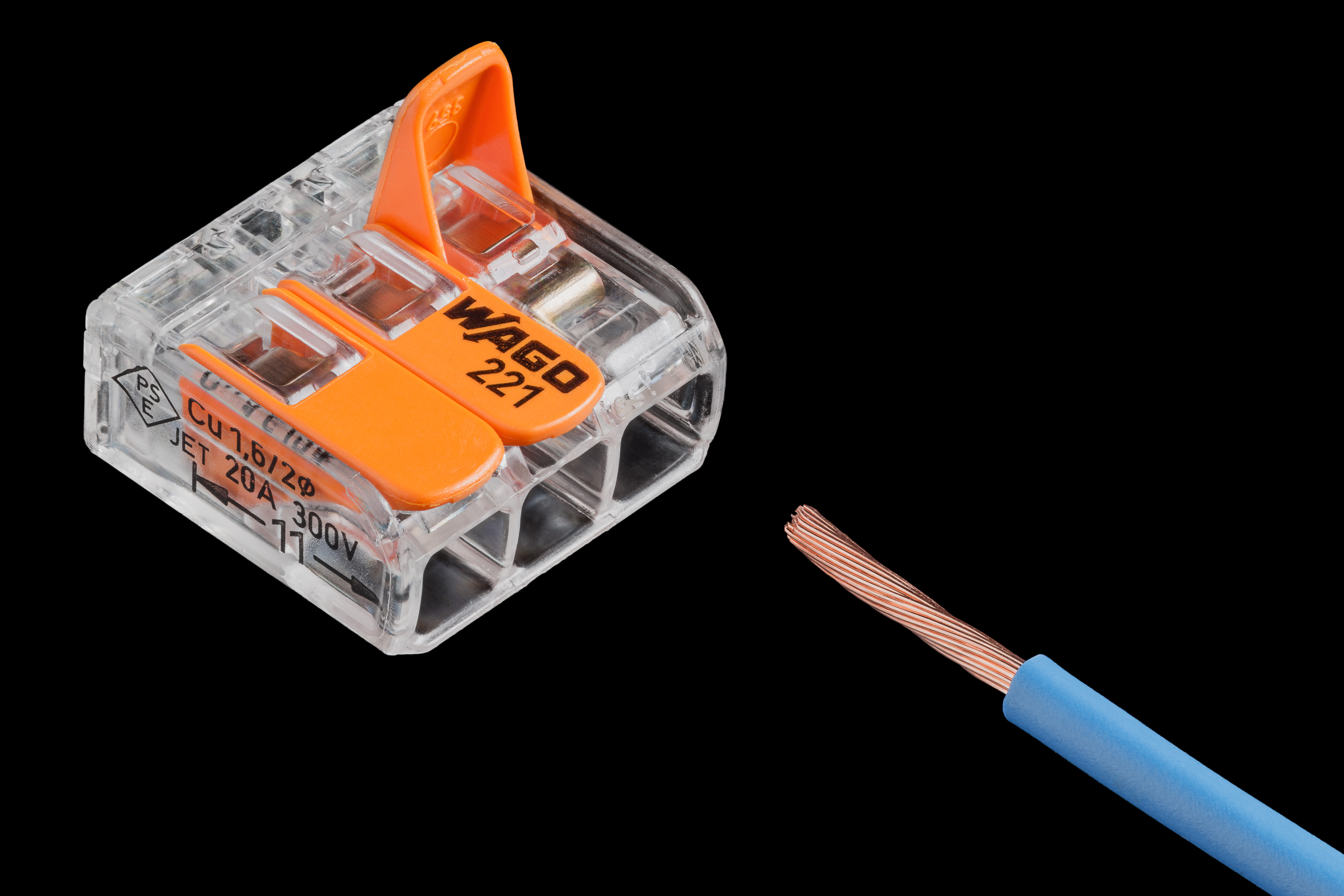
A ferrule changes the conductor end; it does not change the circuit rating
In an approved connection system, a ferrule can contain strands and create a controlled end geometry. It is not a universal adapter, an ampacity upgrade, or permission to use multiple conductors.

A ferrule can support
- Containment of individual strands in a documented connection system.
- A repeatable conductor-end condition for direct insertion where the exact terminal permits it.
- Controlled harness processing and traceability across repeated production.
- Protection of a prepared end when the product instructions support that interface.
- A defined single or twin accessory choice within a qualified process.
A ferrule does not
- Increase cable ampacity, terminal current, bridge current, fault capability, or enclosure thermal capacity.
- Make an unsupported conductor class or size acceptable.
- Override with/without-collar, barrel-length, twin-ferrule, or conductor-count limits.
- Prove contact quality merely because the connection looks neat.
- Replace the terminal instructions, end-product evaluation, or applicable installation rules.
A different wire supplier, ferrule manufacturer, barrel length, collar profile, metal sleeve, crimp die, tool condition, or process setting can change the documented connection. Maintain an approved wire–ferrule–tool matrix and review substitutions before release.
Read the data sheet as a connection matrix
Do not stop at the nominal terminal size or headline current. Capture the exact row, revision, accessories, and conditions that match the conductor actually purchased and the production method actually used.
Exact terminal and function
Freeze manufacturer, series, catalog number, suffix, color or function variant, revision, rail, levels, and approved accessory family.
- Retain the current data sheet.
- Track product-change notices.
- Do not infer from a similar series.
Construction and actual range
Record copper material, wire family, strand category, actual AWG/mm², insulation, temperature rating, and preparation before comparing.
- Separate bare and ferruled rows.
- Separate direct and assisted ranges.
- Separate single and twin entries.
Ferrule, bonded end, or bare
Capture with/without-sleeve conditions, collar/barrel geometry, twin arrangement, strip length, and the approved processing evidence.
- Do not substitute by color code.
- Do not treat tip bonding as a ferrule.
- Use the stated inspection criteria.
Direct insertion or actuation
Write the exact connection mode into the drawing and work instruction. Name the required pusher, button, lever, tool slot, or opening tool where applicable.
- Spring clamps have no tightening torque.
- Accessories may have separate torque.
- Never copy a generic strip length.
Current, heat, bridge, and fault duty
Trace the conductor, clamp, current bar, jumper, feed-in, protection, output conductor, enclosure, and assembly fault-duty basis.
- Keep continuous, thermal, voltage, and fault checks in their own domains.
- Bridge ratings can differ from terminal ratings.
- IEC short-time withstand is not automatically a UL SCCR.
Exact market and service conditions
Match IEC/UL/CSA data, Conditions of Acceptability, factory/field-wiring status, ambient, vibration, contamination, enclosure, and end-product rules.
- Keep rating systems separate.
- Use exact model certificates.
- Preserve strain relief and motion control.
IEC 60947-7-1:2025 is the current fourth edition for supported terminal blocks for copper conductors. ANSI/UL 1059 is active as the sixth edition dated December 11, 2024 and states that compliance alone does not assure suitability in a particular end product. UL Recognized Components remain subject to Conditions of Acceptability. UL 486F evidence for a ferrule/tool system does not by itself approve that ferrule in every terminal block. Use the SENTOP UL 1059 terminal-block checklist for the wider component-evidence review.
Fine-stranded compatibility does not finish the electrical design
The conductor end is one interface in a longer current, thermal, mechanical, and approval path. A connection can be mechanically insertable yet unsuitable for the circuit or assembly.
Continuous, peak, and duty cycle
A permitted ferrule or wire range does not increase the circuit load. Check every series element against the actual duty.
Ambient, grouping, and enclosure
Adjacent loaded poles, ventilation, conductor temperature rating, and enclosure design can change the usable operating condition. Do not assume every fixed rail terminal has a pole-count derating curve; use only the exact product’s published current-temperature data.
Bridge, jumper, and feed-in
The accessory carrying combined current may have a different limit from the individual terminal. Verify every exact part and position.
Protection and available current
Normal current, IEC short-time withstand evidence, UL SCCR, and protective-device interrupting ratings are different characteristics.
Strain relief and motion
Flexible cable does not transfer movement into the clamping point safely by itself. Qualify cable routing, strain relief, bend, vibration, inspection, and any required conductor-retention evidence.
Panel approval and documentation
Verify exact component conditions, conductor rules, accessories, assembly design, destination market, and released work instructions.
Evaluate conductor ampacity, terminal and accessory current, thermal limits, protective-device settings, voltage and insulation, IEC short-time withstand, and UL SCCR under their own stated conditions. The design must satisfy every applicable requirement; one rating cannot be substituted for another.
Do not claim every spring connection is vibration-proof or every screw connection will loosen. Fine stranding does not make the clamping point a flex joint. Compare the exact test method and severity, cable motion duty, mounting, conductor and ferrule configuration, accessories, routing, strain relief, acceptance criteria, and certificate.
The same conductor question changes with the use case
Fine-stranded wire can support compact routing and service access, but each application adds constraints that physical insertion cannot answer.
Map potential distribution
Verify terminal function, common arrangement, bridges, branch protection, labeling, wire range, and the exact direct or assisted connection method.
Protect the signal system
Confirm cable construction, shielding and grounding, field environment, service replacement, polarity, marker system, and terminal acceptance.
Separate cable life from terminal data
The moving cable, bend radius, flex cycles, routing, strain relief, and terminal vibration evidence are separate qualification items.
Control the production combination
Freeze wire, terminal, ferrule, tool, accessories, work instruction, first-article checks, traceability, and substitution policy across shifts and sites.
Do not approve a look-alike
Identify the original and replacement part, conductor preparation, accessory line-up, duty, approvals, and formal change record. If the original model is missing, use the unknown-model cross-reference workflow.
Preserve ratings by jurisdiction
Check load, inrush, heat, bridge/feed-in limits, fault protection, UL/IEC conductor columns, certificates, and customer specifications separately.
Turn the approved connection into a controlled production system
The aim is not merely to make one sample work. Procurement, engineering, production, quality, and maintenance should all be able to identify the same approved configuration and evidence revision.
Freeze the design identity
Record exact terminal, function, wire family, conductor category, size range, preparation, accessories, approval basis, and document revision.
Build the connection matrix
Separate bare, ferruled, bonded, direct-insertion, assisted, single-conductor, and twin arrangements. Mark unsupported combinations clearly.
Qualify the real materials
Review the actual wire, ferrule, tool/die, bridge, feed-in, and terminal lot or revision—not generic descriptions from a purchase order.
Release a clear instruction
Name the connection mode and exact preparation data. Do not publish a generic strip length, crimp setting, actuation, or inspection rule across families.
Verify the first article
Check the released material identities, preparation, full insertion/engagement evidence, conductor retention, accessories, labels, and required electrical tests.
Train by configuration
Show the approved direct and assisted paths for the specific station. Do not teach “all push-in terminals work the same.”
Control substitutions
Require engineering approval for changes to terminal, wire, ferrule, tool, accessory, supplier, process, or manufacturer documentation.
Retain traceability
Keep the evidence, approvals, first-article results, revision, training, PCN review, and spare-part records available to future service teams.
Eight shortcuts that create rework or an unverified connection
“It fits, so it is approved.”
Physical entry is not evidence of conductor acceptance, contact performance, retention, spacing, or end-product approval.
“Push-in accepts all bare wire.”
Direct insertion and assisted spring opening can have different conductor ranges within one family.
“Ferrules are always required.”
Some exact products permit bare flexible conductors through a documented actuated path. Follow the actual model data.
“A ferrule fixes ampacity.”
It does not increase wire, terminal, bridge, protective-device, fault, or enclosure thermal ratings.
“Two small wires equal one.”
Conductor count, geometry, twin-ferrule profile, spring force, current sharing, and evaluated conditions can differ.
“A related series uses the same rule.”
Clamp geometry, direct-push range, ferrule rows, accessories, and certificates can change by part number and revision.
“The distributor summary is enough.”
Catalog listings often omit preparation, direct-insertion, conductor-count, and end-product conditions.
“A mark or standard reference approves the panel.”
A UL mark, IEC standard reference, declaration, or certificate is evidence—not blanket approval. Verify exact-model conditions and the actual end product.
Ask for a documented connection system—not a generic push-in terminal
Send the real wire, preparation, connection-mode, circuit, environment, approval, and production inputs. Ask the supplier to answer with exact part-number evidence and limitations.
Specify the approved connection system: exact terminal, conductor category and size range, permitted end preparation, conductor count, connection mode, accessories, approval basis, destination market, and evidence revision. Avoid buying by nominal cross-section or the phrase “push-in terminal” alone.
Fine-stranded wire and push-in terminal questions answered
Can bare fine-stranded wire be pushed directly into a push-in terminal block?
Only when the exact terminal documentation explicitly permits that conductor construction and size for direct insertion. Some products accept bare fine-stranded wire only after the spring is opened with a pusher, button, lever, or specified tool. General flexible-wire acceptance is not proof of tool-free direct insertion.
Do push-in terminal blocks always require ferrules for fine-stranded wire?
No. A ferrule may be required for direct insertion, permitted but unnecessary for an assisted connection, or handled differently by another terminal technology. Follow the exact model’s bare and ferruled ranges and connection-mode instructions rather than a cross-brand shop rule.
Does a ferrule increase the current rating of the wire or terminal?
No. A ferrule is a conductor-end preparation. It does not raise cable ampacity, terminal current, jumper current, protective-device rating, short-circuit capability, or enclosure thermal capacity. Check the complete current path under the actual duty and temperature conditions.
What is the difference between fine-stranded wire accepted and directly pluggable?
Accepted can mean the conductor is permitted when the spring is opened through the documented operating mechanism. Directly pluggable means the prepared end may enter without that actuation under a separate stated range. Record the exact mode used by the released design.
Can two fine-stranded wires share one push-in terminal point?
Only if the exact clamping unit explicitly permits the conductor count and configuration. The product may list a two-conductor range, a twin-ferrule range, or neither. Two smaller conductors are not automatically equivalent to one larger conductor.
Can any ferrule that matches the nominal wire size be used?
No. The terminal may distinguish ferrules with or without a sleeve, barrel or collar geometry, single and twin forms, pin length, and different ranges. The actual ferrule, crimp and tool system, conductor, and terminal must belong to an approved documented combination.
Is a tip-bonded or ultrasonically welded end equivalent to a ferrule?
Not automatically. It is a different preparation and can have its own restrictions. Use it only when the exact terminal documentation accepts that preparation for the intended conductor size and direct or assisted connection mode.
Does a UL mark or IEC standard reference approve every fine-stranded-wire combination?
No. A mark, standard reference, declaration, or certificate is evidence—not blanket approval. Verify the exact catalog number, conductor and preparation rows, recognition or certificate conditions, manufacturer instructions, accessories, target-market rules, and final panel requirements.
What should maintenance do when an installed connection lacks documentation?
Treat it as a controlled engineering issue. Identify the exact terminal, conductor, preparation, connection mode, load, accessory path, environment, and approval basis. Prior service without a failure and visual fit are not evidence that an undocumented configuration is approved.
When should another connection technology be considered?
Consider another documented terminal family or distribution architecture when the selected product does not support the real wire construction, end preparation, conductor count, service method, environment, electrical duty, or approval basis. Make the change through engineering review, not at the wiring station.
Standards and official manufacturer evidence
Technology pages explain mechanisms; current part-number data releases a configuration. Verify the exact model and document revision before production.
- IEC 60228:2023 — conductor construction and nominal cross-section context; it does not approve a conductor for a particular terminal. Official IEC page.
- IEC 60947-7-1:2025 — current product-standard scope for copper-conductor terminal blocks and screw/screwless clamping units. Official IEC page.
- UL 1059, Edition 6 — terminal-block components; compliance alone does not establish suitability in every end product. Official UL page.
- UL Component Recognition — Conditions of Acceptability and the end-product boundary for Recognized Components. UL guidance.
- UL Connector Certification Services — ferrule and connector certification context, including UL 486F routes. UL overview.
- UL 486F, Edition 3 — ferrule product-evaluation scope; this evidence does not by itself approve a ferrule in every terminal block. Official UL page.
- WAGO connection technology — distinction between direct push-in categories and the actuated universal termination path. Manufacturer overview.
- WAGO TOPJOB S variants — manufacturer examples for direct insertion, fine-stranded conductors with ferrules, tip bonding, pins, and other conditions. Manufacturer page.
- Weidmüller PUSH IN technology — direct insertion and pusher-assisted connection examples for different conductor ends. Manufacturer page.
- Weidmüller wire-end ferrules — ferrule forms and validated ferrule/tool system context. Manufacturer page.
- Phoenix Contact PT 2,5 — part-number example separating flexible, ferruled, twin-ferrule, and directly pluggable conductor rows. Product data.
- Phoenix Contact Push-X — technology-specific direct connection of flexible conductors without ferrules; the claim does not transfer to other product families. Manufacturer page.
- WAGO 2200-2201 — exact-model conductor and strip-length data illustrating why family values cannot be borrowed. Manufacturer product page.
- Phoenix Contact terminal-block electrical tests — voltage drop, temperature rise, short-time withstand, and controlled test configurations. Manufacturer test page.
- Weidmüller electrical testing — temperature-rise, short-circuit, and derating context for defined terminal configurations. Manufacturer test page.
- OSHA 29 CFR 1910.333 — U.S. workplace de-energization, lockout/tagout, verification, and qualified-person boundary. Official OSHA rule.
Release the documented connection—not the push-in label
Send SENTOP the exact wire data, terminal function, preferred end preparation, connection mode, current and voltage, bridge/feed-in arrangement, environment, quantity, destination market, and document requirements. The output should be an exact model and evidence package, not a generic compatibility promise.
