

Ferrules in Spring and Screw Terminal Blocks: When Are They Required?
Ferrules are not universally required in spring or screw terminal blocks. Use one only when the exact terminal or equipment instructions, certification conditions, applicable rules, or an approved project procedure requires or permits that conductor-and-ferrule combination. The words “spring” and “screw” are not enough to decide.
Cabinet terminal-block scene. Photo: tony_duell, CC BY 2.0, via Wikimedia Commons; cropped and darkened for the hero. The image does not establish conductor preparation, ratings, or compliance.
Required, optional, or not approved?
Do not start with habit. Pass the proposed connection through four evidence gates. If one gate is missing, the interface is not ready for a drawing, work instruction, purchase order, or production release.
Identify the exact connection
Record the terminal-block part number, end-equipment model, clamping unit, accessories, and certification route. Similar housings can have different conductor rules.
Classify the conductor
Confirm copper material, solid/stranded/flexible construction, actual AWG or mm², strand class when relevant, insulation, and the number of conductors per point.
Find the matching data row
Use the row for bare flexible wire, ferrule with or without collar, or twin ferrule. The nominal terminal cross-section is not enough.
Preserve the approved system
Match ferrule, tool, die/profile, strip length, insertion method, screw torque where applicable, panel rules, and inspection evidence.
A ferrule changes the conductor end. A sleeve or collar that fits physically may still sit outside the terminal’s documented conductor range, prevent full insertion, change spacing, or conflict with the equipment certification.
Treat every ferrule decision as an approved interface
This matrix separates a real requirement from a useful shop preference. It does not replace the exact manufacturer data or the applicable panel and installation rules.
| Situation | Status | Evidence to check | Decision |
|---|---|---|---|
| Exact terminal or equipment instructions call for a ferrule | Required | Conductor type and size, ferrule style and length, collar, tool/profile, strip length, and installation method. | Use the documented system. Do not substitute a similar ferrule by color or appearance. |
| Exact data accepts bare flexible copper but has no ferrule row | Bare method proven | Flexibility/stranding class, bare-conductor range, strip length, clamp operating method, and project specification. | Only the bare method is established. Do not call the ferrule optional until separate ferruled-conductor evidence is found. |
| Exact data lists both bare and ferruled ranges | Process choice | Separate ranges with and without collar, barrel length, entry geometry, current/temperature conditions, and certification record. | Standardize one documented shop method for repeatability; do not claim a universal performance gain. |
| Push-in production requires direct insertion | Model-specific | Whether rigid or ferruled conductors insert directly and whether bare flexible wire is accepted by opening the spring. | A ferrule may support the chosen direct-insertion process without being an electrical requirement. |
| Two conductors must share a connection point | Separate approval | Permitted conductor count, individual sizes, dedicated twin-ferrule range, barrel length, tool, and terminal geometry. | Use a twin ferrule only when explicitly permitted. Otherwise use a bridge, distribution terminal, or another approved method. |
| No matching ferrule row or documentation exists | Stop | Exact terminal data, certification conditions, and manufacturer direction. | Physical fit is not approval. Do not force the conductor or treat a ferrule as an adapter. |
| Insulation-displacement or other incompatible connection | Not generic | The connection device’s intended termination method and certification scope. | Do not add a ferrule unless the exact product explicitly provides a ferruled connection route. |
IEC 60947-7-1:2025 covers terminal blocks for copper conductors with screw-type or screwless clamping units and includes conductors with or without special preparation. That scope does not impose one ferrule rule on every product. See the official IEC scope.
A ferrule contains strands—it does not certify the connection
A wire-end ferrule, also called a bootlace ferrule, is a metal sleeve crimped over the stripped end of a stranded copper conductor. An insulated version adds a plastic collar at the wire entry. Its practical value is strand containment and a controlled insertion shape for a repeated assembly process.
A ferrule is not the same as a ring lug, fork lug, pin adapter, splice, or a field-soldered wire end. It also is not a repair for nicked, oxidized, undersized, or otherwise damaged conductor. The ferrule, conductor, crimp, and terminal must form one compatible connection.
The ferrule barrel, collar, crimp profile, and finished length can make a prepared conductor larger or differently shaped than the bare conductor. That is why many terminal data sheets publish different maximums for bare flexible wire, ferrules without collars, ferrules with collars, and twin ferrules.
- Do not size by collar color alone. Color systems vary by product family and market.
- Do not assume AWG and mm² rows are direct mathematical equivalents. Use the declared range in the applicable rating system.
- Do not assume a ferrule raises ampacity. Finished performance belongs to the tested terminal/conductor/ferrule system and stated conditions.

Spring and screw terminals can both accept prepared or unprepared conductors
The internal clamping construction, conductor table, and operating method decide the approved route. A broad family label does not.
Bare flexible wire may be intended
The spring is opened with the product’s tool, button, or lever, then the conductor is inserted. Selected systems accept fine-stranded copper without pretreatment; ferrules can remain optional.
- Confirm conductor class and range.
- Confirm the required operating method.
- Do not transfer one brand’s claim to every spring terminal.
Insertion route and electrical acceptance differ
Selected push-in terminals accept rigid or ferruled conductors directly. The same terminal may accept bare flexible wire only after the spring is opened. Direct insertion is not the same as a ferrule mandate.
- Check stiffness and prepared-wire rows.
- Check whether the collar clears the entry.
- Follow the exact release and insertion method.
Some designs accept flexible wire directly
Newer pre-opened spring systems can accept flexible conductors with or without ferrules. This is a product-family capability, not proof that every screwless terminal behaves the same way.
- Verify the exact catalog number.
- Keep the product-specific visual/insertion check.
- Do not infer ratings from the mechanism name.
The screw may not touch the strands
A wire guard, pressure plate, or similar part can protect the conductor from direct screw action. Selected products explicitly allow flexible copper without ferrules.
- Use the stated conductor row.
- Apply only the exact published torque.
- Do not add a ferrule that exceeds the entry envelope.
Bare and ferruled ranges can coexist
The clamping part draws the conductor against the current bar. Product data may list separate ranges for flexible, ferruled, and twin-ferruled conductors.
- Read each row independently.
- Check collar and barrel length.
- Keep ferrule use inside the certified configuration.
Do not substitute a bootlace ferrule for a lug
Some equipment terminals apply a screw directly or use a stud intended for a listed ring, fork, pin, or other lug. Use the exact required termination; a wire-end ferrule is not a universal adapter.
- Identify the interface construction.
- Check lug/ferrule product category.
- Preserve barriers, covers, and spacing.
Spring geometry can change the insertion method
A spring-contact cutaway helps explain the force path, but it cannot show which bare or prepared conductors are approved. Confirm whether the chamber is normally closed or pre-opened, how flexible wire is introduced, and which ferrule profiles fit the entry.
If production wants tool-free direct insertion, record that as a process requirement. Then select an exact terminal and conductor preparation that documents it. Do not rewrite “faster insertion” as “ferrules are mandatory.”
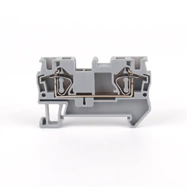
WAGO states that ferrules can be used but are not required for its cited CAGE CLAMP system. Phoenix Contact documents Push-in systems where rigid or ferruled conductors insert directly while bare flexible wire uses the pushbutton, and wire-guard screw connections where ferrules are unnecessary. Those statements apply to the cited technologies and exact product data—not to every terminal on the market.
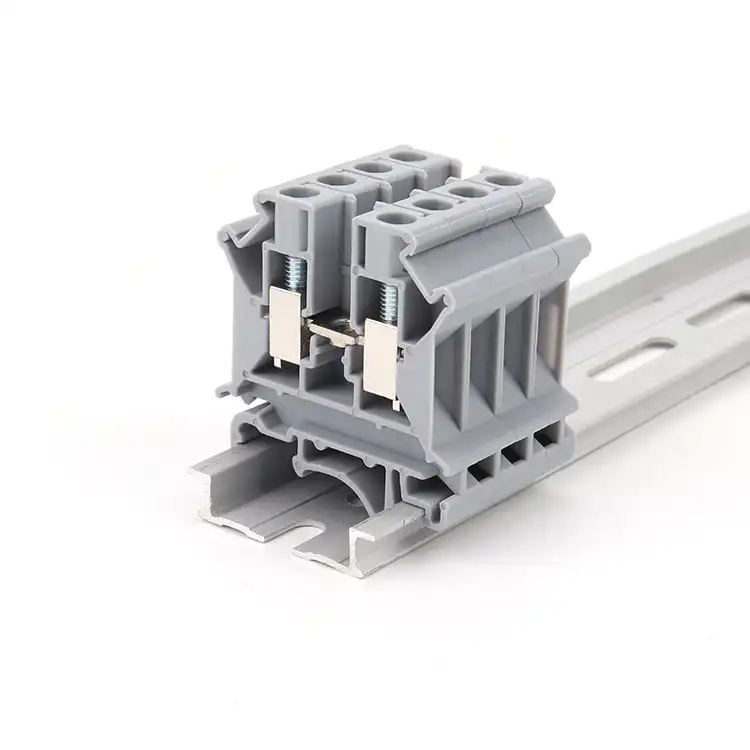
The clamp must match the finished conductor end
Two terminals can both use screws yet contact the conductor in different ways. Two spring terminals can use different chamber states and insertion forces. The visible actuator does not tell you which conductor class, ferrule profile, collar, or number of wires has been evaluated.
This also explains why a ferruled conductor may not fit a terminal whose bare-wire range appears to include the same nominal cross-section. The crimped sleeve and collar change the physical envelope. The applicable ferrule row—not the largest headline wire size—controls the answer.
- Spring terminals: never invent a tightening torque; use the stated operating tool and insertion check.
- Screw terminals: apply the exact torque with a suitable controlled tool where the instructions require it.
- Stud or barrier interfaces: use the listed lug or conductor preparation specified for the exact connection.
- All types: connect only the number, material, construction, and size of conductors documented for one clamping unit.
For product-family context, compare SENTOP spring terminal blocks and screw terminal blocks, then request the exact model data before fixing the conductor-preparation method.
The headline wire size is not the ferrule range
Product pages often show a nominal cross-section first. The connection table underneath may contain several narrower rows. Keep the standard column, conductor construction, connection level, and product revision attached to every value.
| Data field | Question it answers | What not to infer |
|---|---|---|
| Exact part number and revision | Which current terminal, connection level, accessory set, and document control the interface? | A nearby catalog number, family brochure, product photo, or older PDF does not establish the same conductor rules. |
| Conductor material and class | Does the row cover copper; solid, stranded, flexible, fine-stranded, compacted, or another stated preparation? | The everyday word “stranded” is not proof that every strand class uses the same range. |
| Bare flexible conductor | May a stripped flexible conductor be connected directly, and by which actuation method? | Permission for bare flexible wire does not establish permission for a ferrule. |
| Ferrule without collar | Which finished conductor sizes and crimp geometry are accepted without an insulating collar? | The bare-conductor maximum cannot be transferred to this row. |
| Ferrule with collar | Does the collar fit the entry, and is its ferruled range different? | Matching the nominal wire cross-section does not prove the collar clears the housing. |
| Twin ferrule / two conductors | Does one clamping unit accept two same-size conductors in a stated twin-ferrule configuration? | A two-level or two-port terminal does not automatically approve two wires in one clamp. |
| Preparation and insertion | What part-specific stripping/preparation length, barrel relationship, insertion direction, tool, button, lever, or release method applies? | Do not borrow a generic length or a method from a different terminal family. |
| Screw torque or spring operation | What exact torque applies to a screw clamp, or what actuation and insertion check applies to a spring connection? | Spring terminals do not inherit a torque; ferrules do not cancel the specified screw torque. |
| Certification and use conditions | Which IEC/UL/CSA route, field/factory wiring status, temperature, conductor count, and Conditions of Acceptability apply? | A logo or standard number does not approve every catalog suffix or finished panel. |
For a dual-market panel, keep UL AWG data and IEC mm² data in separate evidence columns. Use the terminal-block markings workflow to organize the record.
If the data sheet lists bare flexible conductor but does not list ferruled conductor, it proves only the bare method. It does not make the ferrule “optional.” Obtain a separate approved ferrule row or manufacturer direction before changing the interface.
A ferrule works only as part of a matched system
Treat the conductor, ferrule, preparation, tool or die, finished crimp, terminal, and inspection plan as one controlled process. A sleeve squeezed by ordinary pliers is not a defined ferrule termination.
Identify the conductor
Use the cable specification to record copper material, construction or flexibility class, actual AWG or mm², strand bundle, insulation, and whether one or two conductors are involved.
Select an approved ferrule
Match single or twin construction, barrel and collar geometry, conductor range, material, applicable standard, and the terminal’s separate ferrule row.
Control preparation
Use the part-specific preparation length and a stripping method that does not nick, cut, contaminate, twist away, or leave strands outside the intended sleeve.
Use the identified tool
Match tool or die, crimp profile, size range, condition, calibration or maintenance controls, and full-cycle behavior to the ferrule supplier’s process.
Inspect the finished crimp
Check strand capture, conductor position, sleeve formation, collar condition, finished dimensions, damage, traceability, and any pull or process test required by the approved plan.
Verify the terminal interface
Confirm full insertion, no exposed conductive material outside the intended boundary, correct screw torque or spring actuation, one permitted conductor configuration, and required factory inspection.
Ferrule construction, certification, and tool range do not alone prove that the finished crimp fits or is accepted by a particular terminal. Verify the whole connection.
Flexible, solid, twin, and tinned ends are not interchangeable
The terminal can distinguish conductor construction even when the insulation markings show the same nominal cross-section.
Common use does not equal universal duty
A ferrule can contain fine strands, but selected spring and pressure-plate systems also accept bare fine-stranded copper.
- Match the exact flexibility row.
- Do not promise better electrical or vibration performance because a sleeve was added.
Do not sleeve it by assumption
Ordinary wire-end ferrules address stranded copper. Adding one to solid copper can be unnecessary or unapproved.
- Use it only when the complete system expressly covers solid wire.
- Another solid-wire crimp standard does not grant permission.
Two conductors need their own approval
A twin ferrule joins two same-size stranded copper conductors in one sleeve. It does not increase the conductor count permitted by a one-conductor clamping unit.
- Verify individual sizes, finished geometry, terminal row, and tool.
- If approval is absent, use bridges or another documented distribution method.
Separate plating from field soldering
A factory tin-plated conductor, a tin-plated copper ferrule, and a field solder-tinned wire end are different interfaces. Their acceptance can also change with screw/screwless construction and vibration duty.
- Do not use solder-tinning as an improvised ferrule substitute.
- Follow the exact conductor, terminal, equipment, and service-condition instructions.
A neat-looking wire end can still be the wrong connection
Ferrules on every flexible wire
Some terminals accept bare flexible conductors; others do not establish ferrule use. Read both rows before standardizing.
Using the bare-wire maximum
The ferruled maximum may be smaller, especially when the collar or finished crimp increases the entry envelope.
Choosing by collar color
Color systems can differ. Select from conductor data and the approved ferrule part, then treat color as an aid only.
Crimping with generic pliers
An uncontrolled squeeze can leave poor strand capture, wrong geometry, inadequate retention, or terminal-chamber interference.
Using twin ferrules as a shortcut
A twin ferrule does not convert a one-conductor terminal into a two-conductor-approved clamping unit.
Substituting a ferrule for a lug
A stud or bolt terminal may require an identified ring or fork lug. Never trap a bootlace ferrule under a nut by analogy.
Borrowing length or torque
Preparation length, insertion depth, and screw torque are part-number-specific. A neighboring block is not a reference.
Promising performance from the sleeve
Resistance, temperature rise, vibration, gas-tightness, and service life belong to the tested complete connection and conditions.
A standard can define scope—the exact product still defines use
Ferrule construction, crimp-process evidence, terminal-block evaluation, final-equipment certification, and installation rules are related but distinct layers.
| Reference or record | What it helps establish | What it does not establish |
|---|---|---|
| IEC 60947-7-1:2025 | Scope and requirements for industrial terminal blocks with screw-type or screwless clamping units for round copper conductors, with or without special preparation. | A universal ferrule mandate or proof that every compliant terminal accepts both bare and ferruled conductors. |
| DIN 46228 Parts 1 and 4 | Common tubular ferrule constructions, including uninsulated and insulated forms for the stated conductor types. | Compatibility with a particular terminal, permission for solid wire, or acceptance of a collar/crimp profile. |
| IEC 60352-2:2024 | Requirements and test guidance for solderless crimped connections within its scope. | Terminal-block acceptance, a universal tool/profile, or permission to transfer process settings between ferrules. |
| UL 486F, Third Edition | North American scope for bare and covered ferrules used with stranded copper conductors, including stated one- and two-conductor configurations. | Blanket permission to use a ferrule in every UL 1059 terminal or in an insulation-displacement connection. |
| UL 1059, Sixth Edition | Terminal-block component requirements and evaluation route within scope. | Suitability of the component in every end product; UL explicitly requires end-use conditions to be addressed. |
| UL file / Product iQ / Conditions of Acceptability | Exact covered model, certification category, field/factory wiring status, conductor range/count, temperature, and other use conditions where recorded. | Coverage of every product made by the brand or permission to mix rating systems and accessories. |
| Equipment and panel instructions | The final product’s conductor preparation, terminal use, spacing, inspection, and controlled assembly requirements. | Permission to replace the identified terminal, ferrule, tool, or wire with a similar-looking item. |
Continue with the SENTOP guides to IEC 60947-7-1 and UL 1059. Keep the evidence routes separate.
Do not use a general ferrule article to approve an increased-safety Ex termination, railway/vehicle connection, marine panel, or other special application. Verify the exact certificate, environmental category, product-specific instructions, mounting, conductor system, and governing installation standard.
Four panel scenarios—four evidence paths
These examples show the decision logic. They are not installation instructions or universal product rules.
Ferrules may be a controlled shop choice
The push-in terminal separately accepts ferruled conductors by direct insertion and bare flexible wire after button actuation. A panel shop may standardize ferrules for repeatability if the exact sizes, collars, tools, and checks are documented.
- The process choice is not proof that every push-in terminal needs ferrules.
- Record the approved ferrule and tool in the assembly instruction.
Bare flexible wire may remain the approved method
The current terminal uses a pressure plate and the manufacturer documents bare flexible copper. If the data has no ferruled row, adding a ferrule during maintenance is not an established upgrade.
- Preserve the exact conductor preparation and torque instruction.
- Do not introduce a new interface without product evidence and change control.
Start with the permitted conductor count
If the terminal does not identify a twin-ferrule combination, use a suitable multi-conductor terminal, bridge, or distribution method rather than forcing two wires into one chamber.
- Same potential does not prove same clamping permission.
- Keep bridge current, accessory compatibility, and marking in the BOM.
Keep IEC and UL evidence parallel
The machine build must preserve the terminal’s IEC conductor data and its active UL component record/Conditions of Acceptability where both routes apply. Do not build one hybrid rule from the most generous headline values.
- Track AWG and mm² data separately.
- Lock the exact terminal, ferrule, tool, wire, accessory, and document revisions.
Turn “we always use ferrules” into an auditable wiring standard
Fix the interface identity
Record exact terminal and end-equipment part numbers, connection level, accessories, mounting, certificates, and current controlled documents.
Describe every conductor
Capture copper material, class/stranding, size, insulation, temperature, one or two conductors, factory or field wiring, and target market.
Map approved data rows
Separate bare, ferruled without collar, ferruled with collar, twin ferrule, solid, and other prepared-conductor rows. Mark missing evidence as missing.
Select the process system
Choose ferrule part, tool/die, preparation, crimp profile, insertion or actuation, screw torque if applicable, and inspection criteria.
Verify the build
Use the required incoming inspection, first-article, visual, dimensional, pull, electrical, traceability, and panel verification defined by the product and quality plan.
Control substitutions
Put approved models, wire, ferrule, tool, accessories, documents, and change triggers in the drawing, BOM, work instruction, and handover record.
This workflow supports component selection and factory documentation. It does not authorize exposed electrical work. Qualified personnel must follow the site’s electrical-safety program, identify every source, de-energize and prevent reconnection where required, and verify the safe condition before touching conductors or terminal hardware. Never take torque, preparation length, or energized test steps from this article.
Send the terminal and conductor data—not only “add ferrules”
SENTOP can help compare documented terminal and ferrule options when the exact connection, conductor, market, approval, and production requirements are clear. Final panel design, installation, inspection, and authority approval remain with the responsible project parties.
Wire ferrule decisions for real terminal blocks
Are ferrules required for all spring terminal blocks?
No. Selected spring-cage, push-in, lever, and pre-opened spring systems accept bare stranded or flexible copper within stated ranges. Others use ferrules for direct insertion or require a different actuation method. Check the exact terminal’s conductor table and instructions.
Are ferrules required for all screw terminal blocks?
No. Pressure plates, wire guards, tension sleeves, clamping yokes, direct screws, and stud connections behave differently. Some accept bare flexible copper; some accept ferrules in separate ranges; others require an identified lug. The exact product data and screw torque where applicable govern.
If bare flexible wire is approved, is a ferrule automatically optional?
No. A bare-flexible row proves only that the bare method is permitted. Ferrule use is optional only when a separate ferruled-conductor row, certification record, equipment instruction, or manufacturer direction establishes that configuration.
Do push-in terminals require ferrules for flexible wire?
Not always. Some designs accept ferruled conductors by direct insertion and bare flexible conductors after opening the spring. Other pre-opened designs accept flexible wire with or without a ferrule. Use the exact product’s connection method and conductor data.
Can I use a twin ferrule for two conductors?
Only when the exact terminal separately permits the two-conductor or twin-ferrule combination, including both individual conductor sizes and the finished ferrule geometry. A twin ferrule does not increase a one-conductor terminal’s permitted conductor count.
Can a wire-end ferrule be used on solid wire?
Do not assume so. Ordinary wire-end ferrule standards and products generally address stranded copper. Use a ferrule on solid wire only when the exact ferrule, tool, terminal, and end-equipment documentation expressly cover that combination.
Does North American code require ferrules on every stranded panel wire?
No blanket rule can be applied. Check the ferrule’s UL 486F certification, the terminal’s UL file and Conditions of Acceptability, conductor range and count, field/factory wiring status, the end-product standard and instructions, and project or authority requirements.
Can ordinary pliers be used to crimp a ferrule?
No. Use the identified compatible crimp tool or die and controlled process for the ferrule and conductor. Improvised pliers can create the wrong profile, poor strand capture, inadequate retention, or a finished shape that the terminal does not accept.
Standards scope and manufacturer evidence
Accessed 19 August 2026. Standards pages summarize scope; the controlled full standard, current product data, certification record, and end-equipment instructions remain authoritative.
- IEC 60947-7-1:2025 — terminal blocks for copper conductors.
- IEC 60352-2:2024 — solderless crimped connections.
- DIN 46228-4:2020 — insulated tubular end-sleeves.
- UL 486F, Third Edition — bare and covered ferrules.
- UL 1059, Sixth Edition — terminal blocks.
- UL Solutions — component recognition and Conditions of Acceptability.
- UL Solutions — terminal-block and ferrule certification services.
- WAGO — product-family CAGE CLAMP conductor guidance.
- WAGO — interconnection FAQ, including tinning and gas-tightness boundaries.
- Phoenix Contact — Push-in connection technology.
- Phoenix Contact — screw, wire-guard, and tension-sleeve technologies.
- Phoenix Contact — technical paper: Are ferrules necessary?
- Weidmüller — wire-end ferrules and matched tooling.
- OSHA 1910.333 — U.S. workplace electrical safety-related work practices.
Review the terminal, conductor, ferrule, tool, and market as one system
Share the exact part numbers, conductor data, panel standard, ferrule/tool proposal, quantity, and target market. SENTOP can help compare model options and documentation for a controlled BOM.
