
IEC 60947-7-1:2025 Explained: Terminal Block Requirements and Compliance
IEC 60947-7-1 is the product standard for defined industrial terminal blocks for copper conductors. The current fourth edition was published on April 15, 2025 and replaced the 2009 edition.
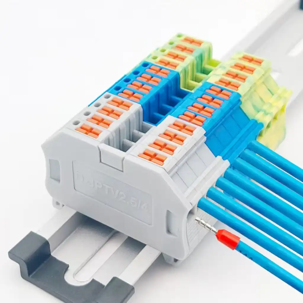
Edition 4.0 replaced the 2009 third edition and has an IEC stability date of 2030.
Round copper conductors, with or without the preparation allowed by the product data.
The AC scope extends to 1,000 Hz; actual product ratings can be much lower.
A certificate or report must identify the model, applicable edition and rating conditions.
Seven checks separate a real compliance file from a generic claim
Use this review before approving a terminal block, supplier declaration or test report. If any answer is missing, record an open action instead of assuming that one family name covers every size, color, accessory and connection variant.
| Check | Evidence to accept | Red flag |
|---|---|---|
| Standard and edition | IEC 60947-7-1:2025, or the adopted national/regional edition required by the project | “IEC compliant” with no document year |
| Product identity | Exact catalog number, suffix, family revision and relevant accessories | Photo, series name or an unrelated size |
| Terminal function | General, test-disconnect or another function matched to the correct Part 7 standard | PE, fuse and PCB products treated as ordinary 7-1 blocks |
| Conductor configuration | Copper conductor type, cross-section, preparation and number per clamping unit | Only maximum wire size is stated |
| Declared ratings | Applicable voltage, current and insulation data tied to the exact approval row | Highest catalog number copied into every market |
| Test or certificate scope | Report/certificate number, issuing body, model coverage and applicable conditions | Logo without a searchable or supplied document |
| Installation data | Strip length, torque or operating method, rail/support, accessories and environment | Installer invents a universal torque or re-torque rule |
First confirm that the product is actually inside Part 7-1
The IEC public abstract defines a narrower product boundary than many marketing pages suggest. It covers industrial or similar terminal blocks fixed to a support, providing an electrical and mechanical connection between round copper conductors through screw-type or screw-less-type clamping units. Annex D addresses defined test-disconnect terminal blocks.
Inside the published scope
- Terminal blocks and Annex D test-disconnect terminal blocks.
- Screw-type or screw-less-type clamping units.
- Round copper conductors, with or without permitted special preparation.
- Cross-sections from 0.05 mm²/30 AWG to 300 mm²/600 kcmil.
- Products primarily for industrial or similar use and fixed to a support.
- Circuits not exceeding 1,000 V AC up to 1,000 Hz or 1,500 V DC.

Match the terminal function to the correct Part 7 document
The standard number is part of the product definition. The table shows the current IEC Webstore publications checked on August 4, 2026; always recheck status before starting a certification project.
| Publication | Main product scope | Selection cue | Do not confuse it with |
|---|---|---|---|
| IEC 60947-7-1:2025 | General terminal blocks and defined test-disconnect terminals for copper conductors | Support-mounted screw or screw-less connection between copper conductors | PE, fuse and PCB functions |
| IEC 60947-7-2:2009 | Protective conductor terminal blocks for copper conductors | PE/PEN function and connection to the fixing support | A normal green-colored feed-through block |
| IEC 60947-7-3:2009 | Safety requirements for defined fuse terminal blocks | Cartridge fuse-link reception and protective function | A disconnect terminal without a fuse |
| IEC 60947-7-4:2019 | PCB terminal blocks for copper conductors | Soldered, press-in or equivalent mounting to a printed circuit board | DIN-rail or other support-mounted blocks |
| UL 1059 / ANSI-UL paths | North American terminal-block certification routes within their defined scopes | Project, authority, end-product and certification requirements in North America | An automatic substitute for an IEC report |
Compliance is a linked system of declared data, construction and tests
Part 7-1 works with the general rules in IEC 60947-1. A reviewer should trace every claimed rating to construction details, conductor preparation, a defined sample configuration and the relevant test sequence—not treat individual test names as isolated badges.
Characteristics and manufacturer information
Identify the terminal function, clamping technology, rated data, conductor range, number of conductors, mounting arrangement and instructions. This information defines what the later evidence can support.
Clamping-unit integrity
The design must secure conductors without unacceptable damage and withstand the mechanical operations applicable to its construction. Screw and screw-less designs are evaluated through their relevant methods.
Conductor acceptance and retention
Solid, stranded and flexible conductors, preparation, ferrules and cross-sections are not interchangeable by assumption. Verify what was tested and what the manufacturer authorizes.
Temperature and contact performance
Current-carrying behavior, voltage-drop/contact behavior and conditioning are evaluated in defined arrangements. Bridges, grouping and conductor size also need product-specific application data.
Dielectric properties
Clearances, creepage distances, impulse behavior and power-frequency withstand depend on the declared insulation system and context. Use the relevant IEC 60947-1 and insulation-coordination provisions.
Short-time withstand behavior
Terminal-block evidence must address the applicable current withstand test and resulting condition. The finished panel still needs its own fault-current and protective-device assessment.
Specified needle-flame verification
The 2025 product standard uses the referenced IEC 60695-11-5 needle-flame method for its defined verification. Glow-wire results and UL 94 material classifications are separate evidence and cannot substitute automatically.
Test-disconnect terminals
Annex D adds requirements for the defined disconnect function. The moving or disconnect element, position and intended operation must match the tested product construction.
Marking and durable instructions
Required identification and manufacturer-stated characteristics must be consistent across the product, packaging, datasheet and evidence. Do not invent a universal “seven markings” checklist.
The wire as inserted is part of the evaluated connection
A nominal “2.5 mm² terminal” description is incomplete. The connection can behave differently with a solid conductor, stranded rigid conductor, flexible conductor, insulated ferrule or twin ferrule. The declared range may also change with the number of conductors in one clamping unit.
Record these values before selecting samples
- Copper conductor construction and applicable metric/AWG size.
- Bare, ferruled or otherwise prepared conductor end.
- Ferrule standard, length and crimp-tool system where used.
- Number of conductors permitted in each clamping unit.
- Strip length and insertion/operating method.
- Declared tightening torque for the exact screw terminal, where applicable.

Six numbers from the old draft should not be treated as universal limits
Some values may appear in particular test conditions, product tables or related standards, but the old article attached them to every terminal block without enough context. Use the purchased 2025 edition, its referenced standards and the exact product documentation.
| Old blanket claim | Why it is unsafe | Publish-safe engineering rule |
|---|---|---|
| “45 K maximum temperature rise” | The 2025 IEC test limit is 45 K in its defined arrangement; it is not a universal field-temperature or product-derating rule. | State the IEC test arrangement, conductor, current and result, then perform the separate equipment thermal assessment. |
| “3.2 mV per connection” | The standard measures at 0.1 times the applicable current-carrying value and limits voltage drop to 3.2 mV per terminal block, with before/after criteria—not at rated current “per connection.” | Quote the report result with its test current, measurement points, conditioning and sample configuration. |
| “8 mm creepage / 5.5 mm clearance at 800 V” | Distances depend on insulation voltage, impulse voltage, overvoltage category, pollution degree, material group, altitude and geometry. | Perform insulation coordination using the applicable IEC 60947-1/IEC 60664 framework and product standard. |
| “0.5–0.6 N·m for every 2.5 mm² terminal” | Torque follows the exact clamping construction, screw, manufacturer declaration and test setup—not wire size alone. | Use the model-specific torque and approved tool; never invent a universal re-torque value. |
| “650 °C or 960 °C glow-wire requirement” | Those blanket glow-wire claims are not the Part 7-1:2025 product requirement. Its defined abnormal-heat/fire check uses the IEC 60695-11-5 needle-flame method. | Verify the specified 10-second flame application and acceptance criteria in the current standard; treat glow-wire and UL 94 as separate evidence. |
| “IP20 minimum for every terminal block” | Open terminal blocks are often components inside enclosures; IP codes describe protection provided by an enclosure or defined product configuration. | Assess contact protection and the completed enclosure separately; state what the IP rating actually covers. |
Evidence must survive contact with the real terminal strip
Certification evidence answers whether defined specimens met a defined scheme. It does not confirm that an installer used the correct conductor preparation, torque, bridge, partition, end plate, rail or environmental protection.
Final verification should connect four records

Six steps move a terminal family from 2009 evidence to a 2025 decision
Do not replace the year in a declaration and call the work complete. The technical revision can affect scope, construction classification, tests, table references and family coverage.
Freeze the baseline
List every catalog number, construction variant, conductor range, material, drawing revision, report and current certificate.
Build an edition delta
Map 2009 clauses/tables to 2025, then flag the published changes that touch each design—especially smaller conductors and CoPI constructions.
Confirm family coverage
Document why tested representatives cover untested sizes or variants. Do not assume one terminal pitch proves the whole catalog.
Close evidence gaps
Obtain engineering evaluation, supplemental testing or a new test program from the appropriate competent/accredited body.
Synchronize documents
Update datasheets, declarations, installation instructions, markings, internal control plans and customer evidence lists together.
Release with change control
Approve the new baseline and define which future material, tooling, supplier or process changes trigger re-evaluation.
IEC publication, test report, certificate, CE and UL answer different questions
The old draft blurred these terms. Keep them separate in technical files and sales copy so buyers can tell what has actually been evaluated.
| Item | What it means | What to verify | What it does not mean |
|---|---|---|---|
| IEC 60947-7-1 | An international product standard containing requirements and test methods | Edition, adopted national version and applicability to the product | That IEC itself certified the terminal |
| Test report | Results for identified samples under stated methods and conditions | Issuer, competence/accreditation, model coverage, edition and complete results | Automatic certification or coverage of every family variant |
| Third-party / CB evidence | Conformity evidence issued within a defined certification scheme | Scheme rules, certificate validity, model list, ratings and national differences | Universal market access without local/end-product review |
| CE marking | The manufacturer's declaration that the product meets all applicable EU legal requirements | Applicable legislation, conformity route, technical file and EU declaration | Approval by IEC, the EU or a generic third-party safety mark |
| UL certification | Evaluation within a defined UL standard/category and certification scope | UL database/file, exact model, conditions of acceptability and applicable ratings | Automatic compliance with the IEC edition or every end-product code |
For a broader market overview, use SENTOP's guide to worldwide terminal block certification standards. For North America, continue with the focused guide to UL 1059 terminal block requirements.
Send these ten inputs to receive a defensible model match
A useful RFQ does more than ask for “IEC terminal blocks.” It defines the circuit, conductor, mechanical layout, market and evidence deliverable.
Need the right terminal block and the right evidence package?
Send the conductor, circuit data, terminal function, rail layout, destination market and required standard edition. SENTOP can help shortlist a model and organize the available model-specific documentation for your review.
- Schematic or terminal plan
- Wire schedule and preparation
- Existing model or clear photos
- Panel layout and rail profile
- Required standard/certificate
- Quantity and destination
Related SENTOP resources
Use this page as the Part 7-1 pillar, then open the focused guide for certification, markings, data-sheet interpretation or another terminal function.
IEC 60947-7-1 terminal block standard: FAQ
Concise answers to the edition, scope and evidence questions that most often cause specification errors.
What is the latest edition of IEC 60947-7-1?
The current IEC publication is IEC 60947-7-1:2025, Edition 4.0, published April 15, 2025. It cancels and replaces IEC 60947-7-1:2009, Edition 3.0. IEC lists a stability date of 2030 for the 2025 edition.
What terminal blocks does IEC 60947-7-1:2025 cover?
It covers terminal blocks and the test-disconnect terminal blocks defined in Annex D, with screw-type or screw-less-type clamping units, primarily for industrial or similar use, fixed to a support and connecting round copper conductors. Its public scope is 0.05 mm²/30 AWG to 300 mm²/600 kcmil and circuits up to 1,000 V AC at 1,000 Hz or 1,500 V DC.
Does IEC 60947-7-1 cover PE, fuse and PCB terminal blocks?
Not as ordinary Part 7-1 products. IEC 60947-7-2 addresses protective-conductor terminals, IEC 60947-7-3 addresses defined fuse terminal blocks and IEC 60947-7-4 addresses PCB terminal blocks. Select the document by terminal function and construction.
Can a 2009 test report prove compliance with the 2025 edition?
Not automatically. The 2025 edition is a technical revision with changed scope, a new CoPI test and reorganized content, among other changes. The manufacturer or competent certification body should document an edition-gap assessment and any supplemental evaluation or testing needed for the exact product family.
Is IEC 60947-7-1 compliance the same as CE marking?
No. IEC 60947-7-1 is a technical product standard. CE marking is the manufacturer's legal declaration that a product meets all applicable EU requirements. The manufacturer must identify the applicable legislation and conformity route; CE is not an IEC or EU approval certificate.
Is UL 1059 equivalent to IEC 60947-7-1?
No. They are separate certification/standard paths with their own scopes, ratings and conditions. A product intended for both IEC and North American projects needs model-specific evidence for each required path; passing one does not automatically establish the other.
Does an IEC 60947-7-1 certificate cover every size in a terminal-block family?
Only if the certificate/report scope and documented family-coverage rules support those variants. Match the exact catalog number, construction, conductor range, accessories, material and ratings. A series name or a photograph is insufficient.
Which documents should a buyer request from a terminal block supplier?
Request the exact model datasheet, installation instructions, applicable declaration, certificate or database record, and—where the project requires it—the complete type-test report. Check the standard edition, product identity, conductor configurations, ratings, accessories, issuing body and change-control status.
References and further reading
Use the purchased standard, adopted national requirements, certification-scheme rules and exact manufacturer evidence for the product being evaluated.
- IEC 60947-7-1:2025 — Terminal blocks for copper conductors — current edition, public scope and published technical changes.
- IEC 60947-7-1:2009 — revised previous edition — previous scope and lifecycle status for migration comparison.
- IEC 60947-1:2020 — General rules — common rules, characteristics, construction, performance and verification framework.
- IEC 60947-7-2:2009 — Protective conductor terminal blocks — PE/PEN product-standard boundary.
- IEC 60947-7-3:2009 — Fuse terminal blocks — safety requirements for defined fuse terminal blocks.
- IEC 60947-7-4:2019 — PCB terminal blocks — board-mounted terminal-block requirements.
- IEC 60715:2017 — Standardized mounting on rails — rail mounting dimensions and functional requirements.
- IEC 60664-1:2020 + AMD1:2025 — Insulation coordination — clearance, creepage and solid-insulation framework.
- IEC 60695-11-5:2016 — Needle-flame test method — referenced fire-hazard test method used by the product standard.
- UL Solutions — Connector Certification Services — UL 1059 and IEC 60947-7 series certification context.
- European Commission — CE marking — manufacturer responsibility and the limits of the CE mark.
- European Commission — Low Voltage Directive — voltage scope and harmonized-standard context for applicable electrical equipment.
- SIST — EN IEC 60947-7-1:2025 adoption record — European adoption and implementation dates.
- EUR-Lex — consolidated LVD harmonized-standards decision — OJEU-cited editions as consolidated on April 30, 2026.
- ILAC MRA signatory search — route to accreditation-body directories and facility scopes.
- IECEE — Taking conformity assessment further — NCB, CBTL, CB Test Certificate and Test Report roles.
- IEC Webstore FAQ — conformity assessment systems — distinguishes IEC publications from IEC third-party conformity-assessment systems.
