
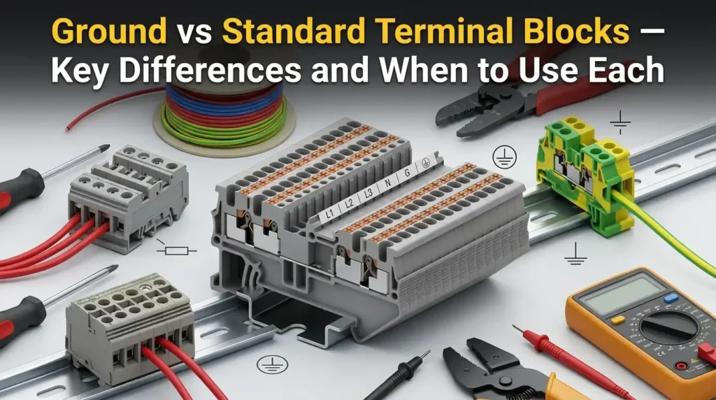
Roughly 80% of electrical faults in industrial control panels trace back to improper wiring or incorrect component selection — and confusing a ground terminal block with a standard terminal block is one of the most common culprits. The core difference: a ground terminal block creates a direct, low-impedance metal-to-metal connection between the conductor and the DIN rail (and therefore the panel enclosure), while a standard terminal block keeps conductors electrically isolated from the mounting rail. Understanding the distinction between a ground terminal block vs standard terminal block isn’t just an academic exercise — it determines whether your equipment meets NEC code requirements, passes inspection, and protects personnel from shock hazards.
Ground vs Standard Terminal Blocks — What Sets Them Apart
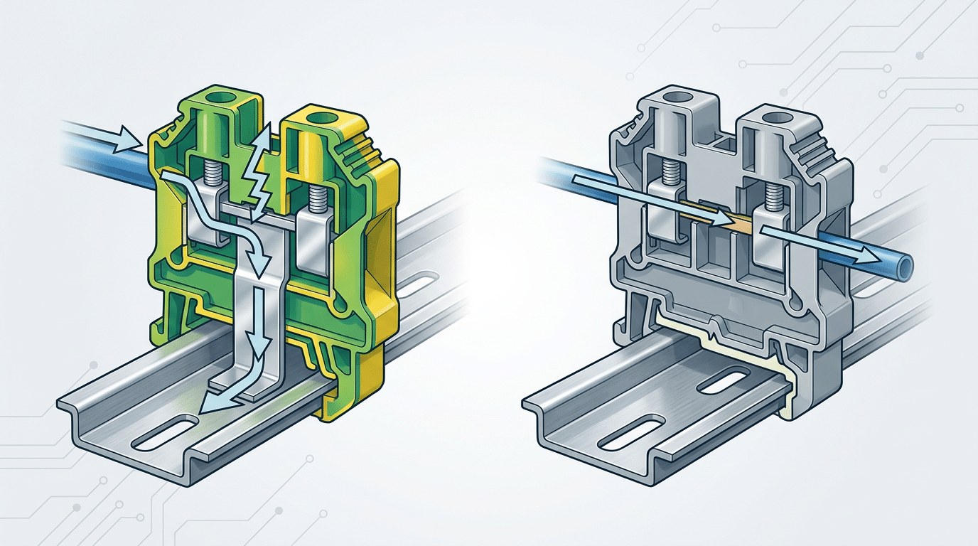
The single most important distinction is the path electricity takes. A ground terminal block creates a direct, low-impedance connection between a conductor and earth ground by making metal-to-metal contact with the DIN rail beneath it. A standard (feed-through) terminal block does nothing of the sort — it simply bridges two conductors so current can pass from one wire to another, electrically isolated from the rail.
Featured Snippet Answer: When comparing a ground terminal block vs standard terminal block, the core difference is grounding function. Ground terminal blocks use an integrated metal foot or mounting plate that bonds directly to a grounded DIN rail, providing protective earth (PE) continuity. Standard feed-through terminal blocks use an insulated housing that keeps conductors electrically separated from the rail, serving only as wire-to-wire connection points.
Why does this matter in practice? According to NFPA 70 (the National Electrical Code), every industrial control panel must maintain a reliable equipment grounding path with no more than 25 ohms of impedance to earth in most installations. A ground terminal block satisfies this requirement at the component level; a standard block cannot.
Here’s a detail many engineers overlook: the housing color isn’t just cosmetic. Ground blocks are manufactured with green or green-yellow housings per IEC 60947-7-1 specifically so they’re identifiable during inspection. Swap one for a standard block by mistake, and you’ve silently broken your protective earth circuit — a fault that won’t show up until something goes wrong.
Throughout this guide, we’ll break down structural differences, code requirements, installation nuances, and real selection criteria so you can confidently specify the right block for every position on your rail. The sections ahead cover each factor in detail, starting with how ground terminal blocks actually achieve their earth bond.
What Is a Ground Terminal Block and How Does It Work
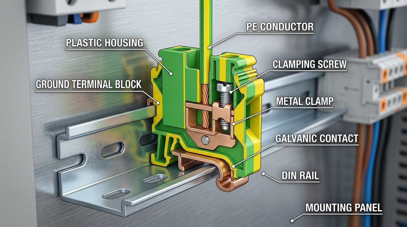
A ground terminal block — sometimes called a PE terminal block or earth terminal block — is a specialized connector whose sole job is bonding a protective earth (PE) conductor directly to a grounded DIN rail. The critical difference from a standard feed-through block lies in one component: a metal mounting foot (or mounting plate) that pierces through the block’s housing and makes direct galvanic contact with the rail beneath it.
Internal Construction: The Metal Foot
Strip a ground terminal block apart and you’ll find a stamped or machined metal bracket — typically zinc-plated steel or tin-plated copper — that extends from the internal clamping mechanism down through the base of the plastic housing. This foot presses firmly against the DIN rail surface when the block snaps into place. Standard terminal blocks deliberately insulate their conductors from the rail; ground blocks do the opposite. That galvanic bridge is the entire point.
Most quality ground blocks achieve a contact resistance below 0.5 mΩ between the PE conductor and the DIN rail, meeting the requirements outlined in IEC 60947-7-1 for protective bonding connections. If that resistance creeps higher — due to oxidation, improper torque, or a poorly grounded rail — your fault-current path degrades and protective devices may not trip fast enough.
Why This Matters for Panel Safety
When a line-to-ground fault occurs inside an enclosure, fault current needs a low-impedance path back to the source so overcurrent protection (breakers, fuses) can clear the fault within milliseconds. The ground terminal block provides exactly that path. By clamping the PE wire and bonding it through the metal foot to a properly grounded DIN rail, you create a continuous earth circuit without running separate grounding busbars — saving both panel space and installation time.
Pro tip: Always verify the DIN rail itself is bonded to the enclosure’s grounding stud with a dedicated rail-to-chassis jumper. A ground block on an ungrounded rail is functionally useless — a mistake that accounts for a surprising number of failed commissioning inspections.
Understanding the ground terminal block vs standard terminal block distinction at this mechanical level makes selection straightforward: if the conductor must bond to earth, choose the block with the metal foot. Everything else follows from that single design choice.
What Is a Standard Feed-Through Terminal Block
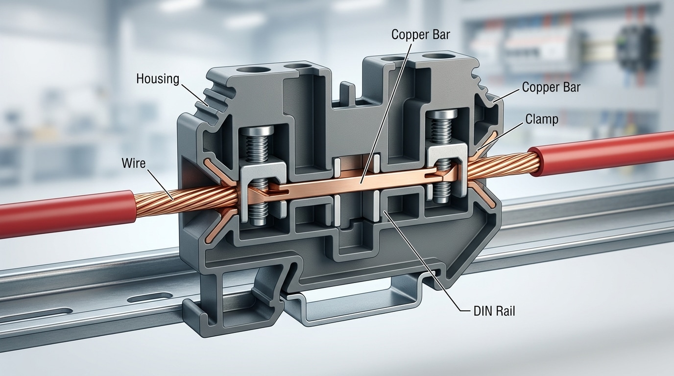
A standard feed-through terminal block is the workhorse of electrical panel wiring. Its job is simple: accept a conductor on one side, pass the electrical signal or power through an internal current bar, and let it exit on the opposite side. The plastic housing — typically made from polyamide (PA 6.6) rated for UL 94 V-0 flammability — completely isolates the conductor from the DIN rail beneath it. No metal-to-rail contact exists. That isolation is exactly what separates it from a ground terminal block in the ground terminal block vs standard terminal block comparison.
The internal clamping mechanism varies by manufacturer. Screw-clamp types remain popular for their simplicity, but spring-loaded (tension clamp) designs from brands like Weidmüller, Phoenix Contact, and WAGO now account for a growing share of the market. Spring clamps reduce installation time by roughly 50% compared to screw types, according to WAGO’s own benchmarking data, and they eliminate the risk of loose connections from vibration over time.
Common Variants Beyond the Basic Feed-Through
- Double-level (two-tier) blocks: Stack two independent circuits vertically on a single DIN rail slot, cutting panel space usage nearly in half.
- Multi-conductor blocks: Accept three or four wires in one housing — ideal for distribution points where a single source feeds multiple branch circuits.
- Disconnect (knife) blocks: Include a removable blade or switch element so you can interrupt the circuit for testing without pulling wires.
What all these variants share is electrical isolation from the mounting rail. They carry signals or distribute power — nothing more. If you accidentally wire a protective earth conductor into a standard block, that conductor has no path to the panel’s grounding bus. This is a critical distinction when evaluating ground terminal block vs standard terminal block suitability for safety circuits.
Pro tip: When specifying standard feed-through blocks, always verify the rated cross-section matches your wire gauge. A block rated for 2.5 mm² will physically accept a 4 mm² conductor in some designs, but the clamping force won’t meet IEC 60947-7-1 pull-out requirements — a common audit failure point.
Key Structural and Electrical Differences at a Glance
Strip away the color coding and catalog numbers, and the ground terminal block vs standard terminal block debate comes down to two things: where the current goes and how the block physically connects to the DIN rail. Every other difference — material, impedance, voltage rating — flows from that fundamental split.
Construction: Insulated Housing vs. Grounding Foot
A standard feed-through block wraps its conductive bar inside a fully insulated polyamide (PA 6.6) housing. The metal never touches the rail. A ground block, by contrast, features a bare metal foot — typically tin-plated copper or zinc-plated steel — that bites directly into the DIN rail surface. This metal-to-metal contact creates a low-impedance bond to earth, and manufacturers like Phoenix Contact specify contact resistance to the rail at ≤ 0.5 mΩ when properly torqued.
Quick-Reference Comparison Table
| Parameter | Ground (PE) Terminal Block | Standard Feed-Through Block |
|---|---|---|
| Housing material | PA 6.6 with exposed metal foot | Fully insulated PA 6.6 |
| Rail contact resistance | ≤ 0.5 mΩ (metal-to-rail bond) | Electrically isolated from rail |
| Typical rated voltage | Up to 800 V (IEC) / 600 V (UL) | Up to 1,000 V (IEC) / 600 V (UL) |
| Current path | Conductor → clamp → foot → DIN rail → earth bus | Conductor in → clamp → conductor out |
| Clamping mechanism | Screw, spring, or push-in (same options) | Screw, spring, or push-in (same options) |
| Primary function | Protective earth bonding | Circuit continuity / signal pass-through |
Why Contact Resistance Matters More Than You Think
That ≤ 0.5 mΩ spec isn’t just a datasheet number. During a ground fault, even a few extra milliohms can slow overcurrent device trip times, leaving equipment and personnel exposed longer. Practical tip: always use a DIN rail with a clean, unpainted mounting surface under the ground block’s foot. A painted or oxidized rail can push contact resistance above 10 mΩ — enough to violate protective earthing requirements in IEC 60364 installations.
One detail often overlooked when comparing a ground terminal block vs standard terminal block: internal clamping force is identical across both types for the same wire gauge. The electrical magic happens entirely at the foot, not the clamp. So if your ground connections feel “loose,” the problem is almost certainly rail contact — not the terminal itself.
Color Coding, Marking Standards, and Visual Identification
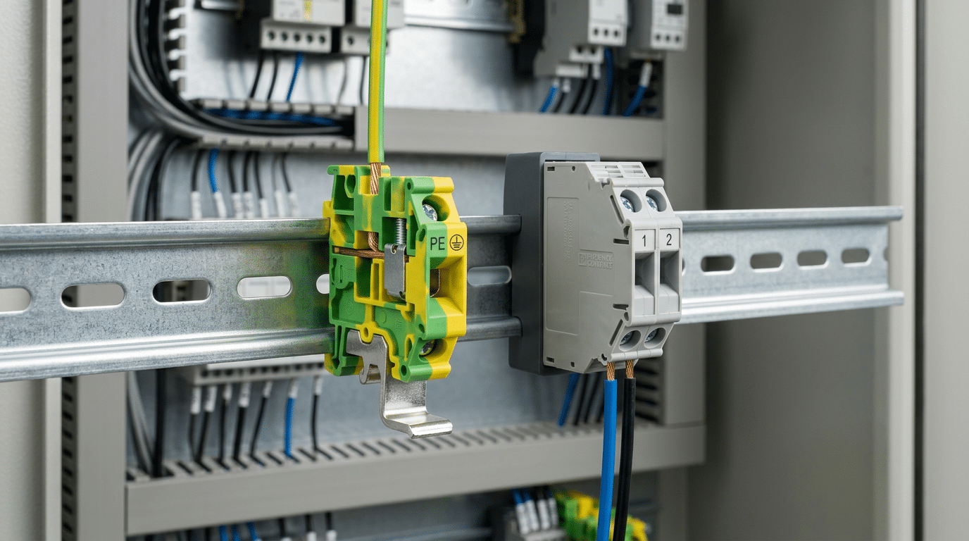
Open any properly wired control panel and your eyes will immediately land on the green-yellow striped blocks. That color isn’t decorative — it’s mandated by IEC 60947-7-1, the international standard governing low-voltage terminal blocks. The green-yellow combination is reserved exclusively for protective earth (PE) connections, and using it on any non-grounding terminal violates the standard outright.
Standard terminal blocks, by contrast, follow a broader palette. Gray is the default for general-purpose power and signal connections. Blue identifies neutral conductors. Orange or red may indicate circuits that remain energized when a main disconnect is opened. Some manufacturers offer black, white, or beige variants for custom labeling schemes. The critical takeaway when comparing a ground terminal block vs standard terminal block visually: green-yellow always means earth, and nothing else should carry that marking.
Why Color Discipline Saves Lives
A 2019 analysis by the Electrical Safety Foundation International found that contact with electrical equipment caused 166 workplace fatalities in a single year in the United States. Misidentified grounding points contribute to these incidents. When a technician troubleshooting a dense panel with 200+ terminals grabs the wrong block, the consequences range from nuisance trips to arc-flash events.
Pro tip: During panel audits, check that no standard feed-through block has been swapped onto a PE rail position. A gray block bolted to a grounded DIN rail looks connected but may lack the internal metal-to-rail contact foot that makes a true ground block effective. This is one of the most common — and most dangerous — installation errors.
Beyond body color, look for the IEC 5019 earth symbol (☷ or the circled vertical line with three horizontal bars) stamped or printed on the housing. Reputable brands like Phoenix Contact, Weidmüller, and Wago include this marking on every PE block. If you’re comparing a ground terminal block vs standard terminal block from an unfamiliar supplier and neither color nor symbol is present, reject the part — compliance cannot be assumed.
- Green-yellow — Protective earth (PE) only
- Blue — Neutral conductor (N)
- Gray / beige — General-purpose line or signal
- Orange / red — Unswitched or always-live circuits
DIN Rail Mounting and Installation Considerations
Here’s where the ground terminal block vs standard terminal block comparison gets hands-on. A standard feed-through block snaps onto any 35mm DIN rail — painted, anodized, galvanized — and works perfectly because it carries no grounding function through the rail itself. Ground blocks are a different story entirely.
Rail Surface Preparation for Ground Blocks
A PE terminal block relies on its metal foot plate making direct, low-resistance contact with the DIN rail to establish earth continuity. That means the rail surface must be bare, conductive metal at every mounting point. Painted or powder-coated rails — common in budget enclosures — will silently defeat your grounding path. Before mounting, scrape or sand the rail at each ground block location down to bright metal, then verify continuity with a milliohm meter. You’re targeting less than 0.1 Ω between the block’s ground contact and the rail’s bonding point to the enclosure.
Pro tip: Many panel builders skip rail prep and rely on the block’s spring teeth to bite through paint. This works initially but degrades over time as oxidation builds beneath the contact point. Don’t gamble on it.
Torque and Common Mistakes
Most manufacturers specify conductor clamping torque between 0.5 Nm and 1.2 Nm depending on wire gauge and terminal size — check the datasheet for your specific block. Under-torquing is the number-one installation error; it creates high-resistance joints that generate heat and eventually fail. Over-torquing damages the conductor strands or cracks the housing.
- Use a calibrated torque screwdriver — not a standard flat-blade driver
- Use ferrules on stranded wire to prevent strand splaying and ensure consistent contact pressure
- Verify DIN rail grounding with a continuity test after all blocks are mounted, not just at initial installation
Standard blocks tolerate slightly more installation variability because a loose connection only affects that circuit. A poorly mounted ground block, however, can compromise protective earth for an entire panel section — a safety hazard that won’t show up until a fault occurs. The NFPA 79 standard for industrial machinery explicitly requires verification of protective bonding circuit integrity, reinforcing why rail preparation isn’t optional.
NEC, IEC, and UL Code Compliance Requirements
Choosing a ground terminal block vs standard terminal block isn’t just an engineering preference — it’s a code mandate. Three overlapping regulatory frameworks govern this decision, and misapplying any one of them can result in failed inspections, costly rework, or worse, an unsafe installation.
NEC Article 250 — Grounding and Bonding
The National Electrical Code (NFPA 70) Article 250 requires that all equipment grounding conductors maintain a continuous, low-impedance path back to the service entrance. A standard feed-through block, isolated from the DIN rail by its housing, breaks that continuity. Inspectors routinely check ground bus continuity with a milliohm meter — anything above 0.1 Ω at a termination point raises a red flag. Using a standard block where a PE block belongs violates Section 250.148’s requirement for proper grounding connections within enclosures.
IEC 60947-7-2 — PE Terminal Block Specifications
This international standard defines the mechanical, electrical, and marking requirements specifically for protective earth (PE) terminal blocks. Key mandates include the green-yellow identification, a metal foot or mounting clip that bonds directly to the DIN rail, and a prohibition against using the PE terminal for any other circuit function. Panels built to IEC standards and exported globally must comply — roughly 68% of industrial control panels shipped internationally reference IEC 60947-7 series requirements.
UL 1059 — Listing Criteria
UL 1059 covers terminal blocks for industrial control equipment in North America. A ground terminal block must pass specific dielectric withstand and grounding-continuity tests that standard blocks are never subjected to. Here’s the practical takeaway: if your panel requires a UL 508A listing, the Nationally Recognized Testing Laboratory (NRTL) auditor will verify that every grounding termination uses a UL-listed PE block — not a standard block with a jumper wire jury-rigged to the rail.
Pro tip from the field: Keep a copy of each terminal block’s UL certification sheet inside the panel door. Inspectors appreciate it, and it eliminates back-and-forth during audits. This single habit can cut panel inspection time by 30 minutes or more.
The bottom line on the ground terminal block vs standard terminal block compliance question is unambiguous: substituting one for the other isn’t a gray area. It’s a documented code violation across NEC, IEC, and UL frameworks simultaneously.
When to Use Ground Terminal Blocks vs Standard Terminal Blocks
Knowing the structural differences is one thing. Knowing exactly which block to reach for during panel layout — that’s where costly mistakes happen or get prevented. The decision between a ground terminal block vs standard terminal block comes down to one question: does this conductor carry operational current, or does it exist solely to protect people and equipment?
Scenarios That Demand Ground Terminal Blocks
- Protective earth (PE) connections: Every equipment grounding conductor in an industrial panel — from VFD chassis grounds to motor PE leads — must terminate on a dedicated ground block with direct metallic contact to the DIN rail and enclosure.
- EMC shielding terminations: Cable shields for analog 4–20 mA signals or high-speed communication lines (PROFINET, EtherNet/IP) need low-impedance paths to ground. A shield-clamp ground block keeps shield drain wires short, which is critical for maintaining EMC integrity in panels with variable frequency drives.
- Lightning and surge protection grounding: SPD modules route transient energy to earth. Their ground leads require a block bonded directly to the grounding bus — never a standard insulated block.
Scenarios Where Standard Blocks Are the Right Call
Power distribution inside a panel — think 24 VDC supply rails feeding PLCs, HMIs, and I/O modules — uses standard feed-through blocks. The same applies to thermocouple and RTD sensor wiring, discrete I/O circuits, and control relay interconnections. In a typical HVAC building automation panel, roughly 70–80% of all terminal positions are standard blocks handling signal and power conductors, with the remaining positions dedicated to PE ground terminations.
Real-World Example: Industrial Automation Panel
In a Siemens S7-1500 PLC cabinet with 12 servo drives, a systems integrator will typically allocate one ground terminal block per drive for the PE conductor, plus a row of shield-clamp ground blocks for encoder and PROFINET cables. Every other connection — 24 VDC power, digital I/O, safety relay wiring — runs through standard blocks. Mixing these up violates NFPA 79 requirements for industrial machinery and can introduce ground loops that corrupt analog signals.
Pro tip from the field: if you’re unsure, check the wire’s function, not its gauge. A 16 AWG wire could be a 24 VDC control signal or an equipment grounding conductor — the terminal block type must match the conductor’s purpose, not its size.
Common Mistakes and Troubleshooting Tips
The most frequent — and most dangerous — mistake? Substituting a standard feed-through block where a ground terminal block belongs. A standard block’s plastic housing isolates the conductor from the DIN rail, which means your “ground” path has no actual earth connection. This single error accounts for a surprising number of high-resistance ground faults that pass initial inspection but fail under real fault conditions.
Top Errors That Compromise Grounding Integrity
- Assuming DIN rail conductivity: Painted, anodized, or corroded DIN rails can introduce resistance exceeding 1 ohm at the mounting point. Always scrape or sand the rail surface beneath each ground block’s metal foot, and verify continuity with a milliohm meter — not just a basic multimeter beep test.
- Mixing ground and standard blocks without separation: Placing PE blocks adjacent to signal-carrying standard blocks without end stops or partition plates invites accidental cross-contact during maintenance. Use dedicated rail sections or clearly marked barrier plates.
- Ignoring manufacturer torque specs: Under-torqued screws cause micro-arcing and gradual resistance buildup. Over-torqued screws deform the conductor. Most industrial blocks specify 0.5–0.8 Nm for 24–12 AWG connections. A study referenced by OSHA found that loose connections contribute to roughly 25% of electrical equipment failures in industrial settings.
Diagnosing High-Resistance Ground Faults
When a ground fault indicator trips intermittently or RCD sensitivity drifts, the terminal block is often the last place technicians look — but it should be the first. Start by measuring resistance from the PE conductor landing point on the terminal block to the panel’s main ground bus. Anything above 0.1 ohm warrants investigation.
Use a four-wire (Kelvin) resistance test to eliminate lead resistance from your reading. If the ground terminal block vs standard terminal block choice was made correctly but resistance is still high, check the rail-to-block contact point for oxidation. A thin film of corrosion invisible to the eye can add 2–5 ohms — enough to prevent a breaker from tripping within its rated clearing time.
Pro tip: After tightening, tug-test every conductor with approximately 1 lb of force. If it moves, the termination is unreliable regardless of what your torque wrench says.
Frequently Asked Questions About Ground and Standard Terminal Blocks
Can you use a standard terminal block for grounding?
No — and this is the single most dangerous substitution in panel wiring. A standard block’s housing isolates the conductor from the DIN rail, so there is no low-impedance path to earth. Using one as a ground connection violates NEC Article 250 bonding requirements and can leave equipment frames energized during a fault.
Do ground terminal blocks need a special DIN rail?
Not a special rail — but the rail must be bare, uncoated metal. Any standard 35 mm steel or aluminum DIN rail works as long as the zinc or nickel plating is intact and unpainted at the mounting point. The foot of a PE block bites directly into this surface to establish continuity.
What happens if a ground block is installed on a painted rail?
Paint acts as an insulator. Even a 50-micron powder-coat layer can push contact resistance above 1 Ω, which is enough to prevent a breaker from tripping within the required time during a ground fault. Always scrape or sand the rail surface beneath each ground block, then verify with a milliohm meter — you want well under 0.1 Ω.
Are ground terminal blocks required by code?
Yes, wherever protective earth conductors must be terminated inside a panel. IEC 60947-7-2 specifically governs PE terminal blocks, and UL 1059 covers their listing in North America. Inspectors will flag any panel missing dedicated, identifiable ground terminations.
Can ground and standard blocks sit on the same rail?
Absolutely. Most industrial panels mix both types on a single DIN rail. The key difference between a ground terminal block vs standard terminal block in this scenario is that the ground blocks bond to the rail while standard blocks float electrically above it. Separators or end stops keep them organized.
What is the difference between a ground block and a neutral block?
A ground (PE) block connects to earth via the DIN rail. A neutral block is electrically isolated from the rail — just like any standard feed-through block — and carries return current. Mixing them up creates a code violation and can introduce stray current on enclosure surfaces. Look for the green-yellow marking on PE blocks versus blue on neutral blocks per IEC 60446.
Choosing the Right Terminal Block for Your Application
The decision between a ground terminal block vs standard terminal block comes down to one question: does this connection need a direct, low-impedance path to the DIN rail and enclosure ground bus? If yes, ground block. If no, standard feed-through. That’s the core framework — everything else is detail.
But details matter. Before you finalize a bill of materials, run through this checklist:
- Check your applicable codes. NEC Article 250, IEC 60947-7-2, and your local jurisdiction may each impose specific requirements on grounding conductor termination. A 2022 NFPA survey found that 23% of electrical panel deficiencies cited during inspections involved improper grounding connections — a problem that starts at component selection.
- Verify voltage and current ratings from the manufacturer datasheet — not from memory, not from a similar-looking part number. A Phoenix Contact USLKG 5 and a UT 4 look nearly identical at arm’s length, but their functions are fundamentally different.
- Match wire gauge to terminal capacity. Oversized conductors crammed into undersized clamping zones create high-resistance joints that degrade over time, especially on PE circuits where reliability is life-safety critical.
- Document everything. Record part numbers, torque values, and loop impedance test results. Auditors and future technicians will thank you.
Proper grounding is non-negotiable. It is the last line of defense between a fault and a person. Treat every ground terminal block selection as a safety decision, not a procurement shortcut.
For a deeper dive into grounding principles and conductor sizing, the NFPA 70 (National Electrical Code) reference page is the authoritative starting point.
Ready to spec your next panel? Download the manufacturer’s terminal block selection guide for your preferred brand, or reach out to a panel design specialist who can review your schematics against current code requirements. Getting the ground terminal block vs standard terminal block choice right at the design stage costs minutes — getting it wrong costs far more.
See also
9 Common DIN Rail Terminal Block Types and Their Uses
How to Choose the Right Terminal Block for Any Application
What should you know about DIN rail circuit breakers for home and industry
What is a DIN rail mounted miniature circuit breaker and how does it work

