
A single misread rating on a terminal block spec sheet caused a product recall affecting over 12,000 industrial control panels in 2022 — all because an engineer confused IEC and UL current ratings that differed by nearly 40%. Terminal block specifications pack critical electrical, mechanical, and compliance data into dense datasheets, and knowing how to decode each parameter — from voltage derating curves to AWG wire ranges and pitch dimensions — is the difference between a safe, code-compliant design and a costly failure. This guide breaks down every line of a typical terminal block spec sheet with real-world examples, so you can confidently select and verify the right component for your application.
What Terminal Block Specifications Tell You at a Glance
A terminal block datasheet packs a surprising amount of engineering detail into a single page. Knowing which parameters to check first — and which ones trip up even experienced engineers — saves hours of rework and prevents costly field failures.
Every set of terminal block specifications revolves around a handful of critical parameters:
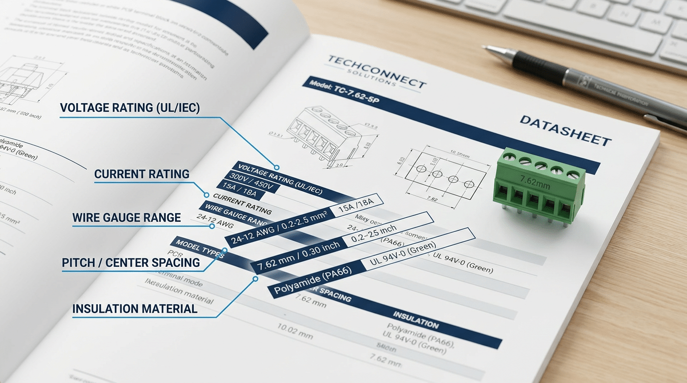
- Voltage rating — the maximum voltage the block can safely insulate, typically listed as both UL (e.g., 300V) and IEC (e.g., 630V) values. These numbers are not interchangeable.
- Current rating — how much continuous current each pole can carry. A common 5.0mm-pitch PCB block might be rated at 20A per IEC 60947-7-1 but only 10A under UL 1059 testing conditions.
- Wire gauge range — expressed in AWG (American Wire Gauge) or mm², defining the smallest and largest conductors the clamping mechanism accepts.
- Pitch — center-to-center distance between adjacent poles, measured in millimeters (e.g., 3.5mm, 5.08mm, 7.62mm).
- Insulation material — usually Nylon 66 (PA66) or polycarbonate, each with different flammability ratings (UL 94 V-0 being the most common requirement).
- Operating temperature range — often −40°C to +105°C for industrial-grade blocks.
Here’s a practical tip most datasheets won’t spell out: the dual UL/IEC rating gap can exceed 50% on the same product. A block rated 32A under IEC standards might only carry 20A under UL derating rules. Always confirm which standard your application demands before comparing current ratings across manufacturers.
Quick rule of thumb: check voltage, current, wire range, and pitch first. If any one of those four doesn’t match your design, nothing else on the spec sheet matters.
How to Read Voltage and Current Ratings Correctly
Most engineers glance at a terminal block’s voltage rating and assume they understand it. They don’t. A single datasheet often lists two distinct voltage values — rated voltage and rated insulation voltage — and confusing them can lead to field failures or compliance rejections.
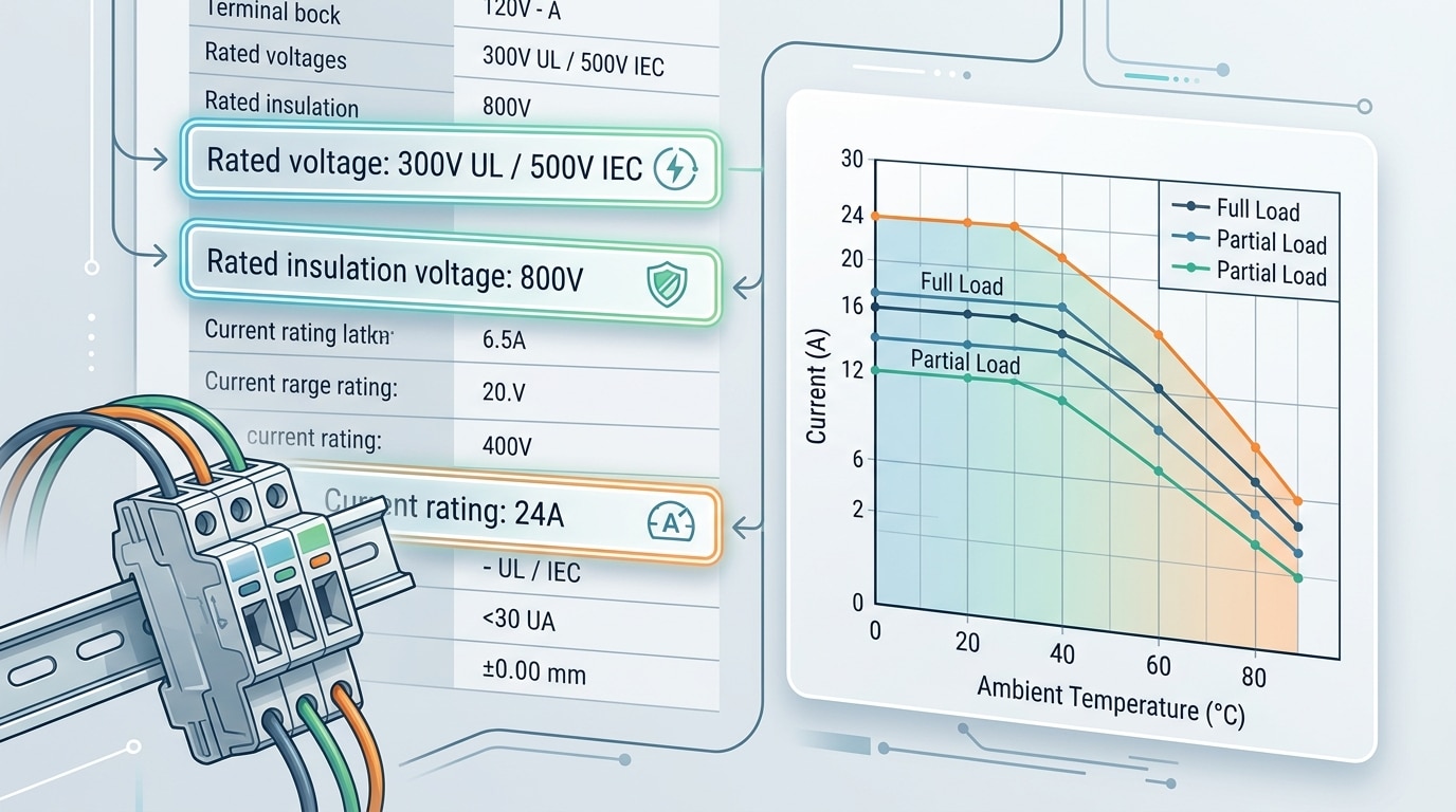
Rated voltage (also called working voltage) is the maximum voltage the terminal block can handle continuously under normal operating conditions. Rated insulation voltage (Ui) defines the dielectric withstand capability of the insulating material itself. For example, a Phoenix Contact PTTB 2.5 lists a rated voltage of 300V per UL and 500V per IEC, yet its rated insulation voltage reaches 800V. That gap exists because UL and IEC use fundamentally different test methodologies — UL tests at the component level with specific spacings, while IEC 60947-7-1 evaluates the entire assembly under pollution degree conditions.
Why Derating Matters More Than the Headline Number
Current ratings on terminal block specifications are determined at a standardized ambient temperature — typically 25°C — with a maximum allowable temperature rise of 45K. Push your ambient to 55°C, and you’ll need to derate that current by roughly 20–30%, depending on the manufacturer’s curve. Skip this step, and you risk exceeding the thermal limits of both the terminal and the connected wire insulation.
Pro tip: Always check whether the datasheet current rating was tested with a single pole loaded or with all poles loaded simultaneously. All-poles-loaded values can be 15–25% lower than single-pole figures — a detail buried in footnotes that catches even experienced panel builders off guard.
When reviewing terminal block specifications for a 300V-rated block, don’t assume it’s interchangeable with a 600V-rated one just because the insulation voltage is high enough. The creepage and clearance distances differ, and your end-product certification (UL 508A, for instance) will enforce the rated working voltage, not the insulation voltage.
Wire Size and AWG Compatibility Explained
Every terminal block spec sheet lists an acceptable wire range — typically something like “24–12 AWG (0.2–4.0 mm²).” That dual notation matters. AWG (American Wire Gauge) counts down as wire diameter increases, which trips up newcomers: 12 AWG is thicker than 24 AWG. The metric mm² value represents the conductor’s cross-sectional area and is standard across IEC-rated components. When reading terminal block specifications, always confirm both values match your conductor — don’t convert loosely in your head, because AWG-to-mm² conversions aren’t perfectly round numbers.
Solid vs. Stranded: Not Interchangeable
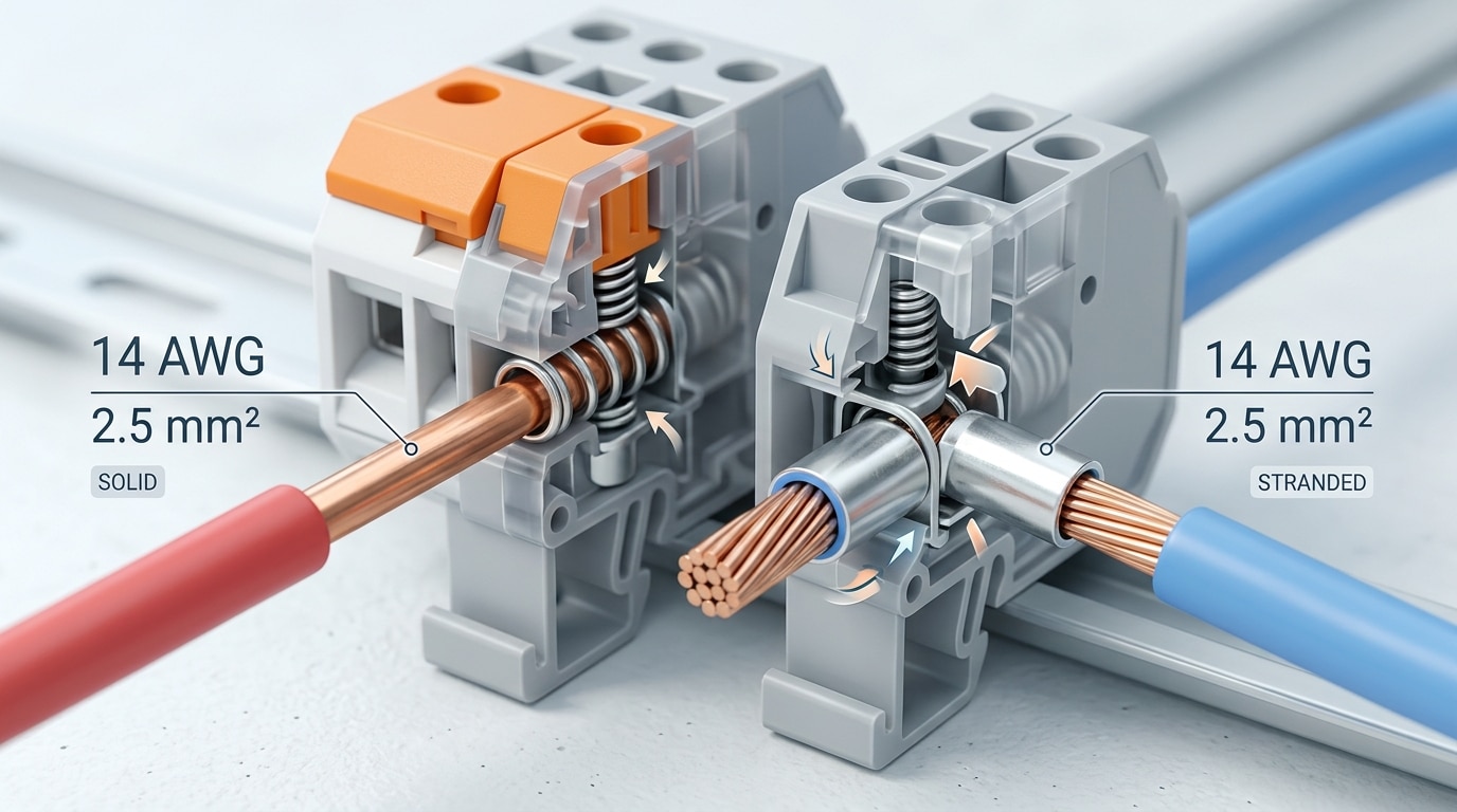
A 14 AWG solid conductor has a single rigid core of 1.628 mm diameter. A 14 AWG stranded conductor bundles many thinner filaments into roughly the same cross-section — but its effective clamping diameter is larger. Many spring-cage terminal blocks accept both, yet screw-clamp types often specify separate ranges: for example, 24–12 AWG solid but only 24–14 AWG stranded. Ignoring this distinction is one of the fastest ways to get a connection that passes a tug test on the bench but fails under thermal cycling.
Strip Length and Clamping Mechanism
Strip length requirements typically fall between 5 mm and 10 mm, depending on the clamping mechanism. Too short, and the conductor doesn’t fully engage the contact zone — Weidmüller’s own testing data shows that under-stripped wires can lose up to 30% of their rated pull-out force. Too long, and bare copper protrudes beyond the housing, creating a short-circuit risk in dense panel layouts.
Pro tip: Use ferrules on stranded wire whenever the terminal block specification permits them. Ferrules consolidate loose strands, prevent whisker shorts, and deliver consistent contact pressure — especially critical in push-in and spring-cage designs.
Match the ferrule size to the conductor’s mm² rating, not the AWG approximation. A DIN 46228-compliant ferrule in the correct color code eliminates guesswork entirely.
Pitch, Spacing, and Dimensional Specs for PCB-Mount Terminal Blocks
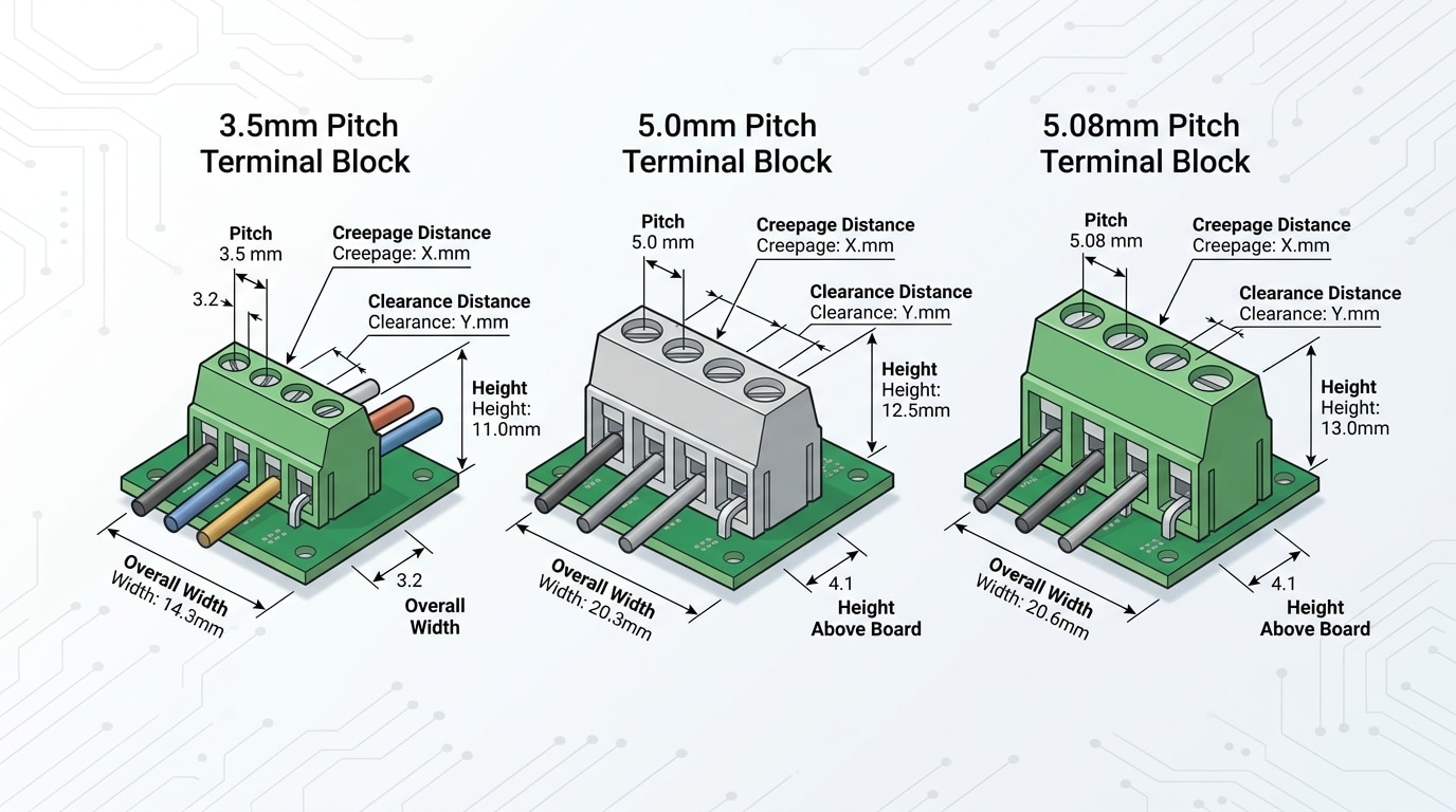
Pitch — the center-to-center distance between adjacent pins — is the single measurement that determines whether a terminal block physically fits your PCB footprint. Get it wrong by half a millimeter and you’re redesigning your board. The three most common pitches you’ll encounter are 3.5 mm, 5.0 mm, and 5.08 mm (the last being the metric equivalent of 0.200 inches, a legacy of imperial-based designs).
Why does 0.08 mm matter? It usually doesn’t — for a 2-position block. But across a 12-position connector, that cumulative error reaches nearly 1 mm, enough to stress solder joints or prevent insertion entirely. Always verify pitch against your EDA library footprint, not just the first and last pin.
Creepage and Clearance: The Hidden Constraints
Beyond pitch, terminal block specifications list two critical safety distances:
- Clearance — the shortest distance through air between two conductive parts.
- Creepage — the shortest distance along a surface between those same parts.
These values are dictated by the pollution degree of your operating environment and the rated voltage. A 3.5 mm pitch block rated at 300 V typically offers around 3.5 mm clearance — barely meeting IEC 60664-1 requirements for Pollution Degree 2 at that voltage. Jumping to a 5.0 mm pitch gives you roughly 40% more creepage, which is why industrial and high-voltage designs almost always specify 5.0 mm or wider.
Practical Pitch Comparison
| Pitch | Typical Max Voltage | Best Use Case |
|---|---|---|
| 3.5 mm | 300 V (IEC) / 150 V (UL) | Signal-level, compact IoT boards |
| 5.0 mm | 300 V (IEC) / 300 V (UL) | General-purpose industrial I/O |
| 5.08 mm | 300 V (IEC) / 300 V (UL) | Drop-in replacement for 0.2″ legacy footprints |
Pro tip: When panel space is tight, check the overall block width and height above board — not just pitch. A 5.0 mm pitch block from one manufacturer can be 2–3 mm taller than a competitor’s, creating clearance issues with enclosure lids.
Dimensional specs also include pin length and solder-pad geometry. Through-hole pins are typically 3.2–3.5 mm long; if your board is thicker than 1.6 mm standard FR-4, confirm that pin protrusion is sufficient for a reliable wave-solder fillet.
UL vs IEC Standards and What the Certification Markings Mean
The same terminal block can carry two wildly different ratings depending on which standard you reference. A block rated 300 V / 25 A under UL 1059 might show 800 V / 32 A under IEC 60947-7-1 — and both numbers are correct. The gap exists because UL testing assumes worst-case conditions (open air, no enclosure), while IEC methods test inside a sealed enclosure at higher ambient temperatures. Ignoring this distinction is one of the fastest ways to misread terminal block specifications.
Rule of thumb: UL ratings are typically 40–60% lower in voltage than IEC ratings for the identical part, because UL enforces larger creepage and clearance distances relative to the rated voltage.
Which Standard Applies to You?
- North America — UL 1059 (industrial connectors) or UL 486E (wire connectors). NEC compliance requires UL-listed components.
- Europe and most international markets — IEC 60947-7-1 (industrial) or IEC 61010-1 (measurement/lab equipment). CE marking depends on these.
- Dual-rated panels for export — Use the lower of the two ratings to satisfy both jurisdictions simultaneously.
Look for the certification logos stamped on the housing or printed on the datasheet: the backwards-UR mark for UL Recognition, the CSA mark for Canadian compliance, and the CE mark for European conformity. A UL listing means the complete product was tested; UL Recognition means only a component was evaluated — a critical difference when your panel inspector shows up.
Pro tip from the field: always cross-check the file number on UL’s online database. Counterfeit UL marks exist, and a 30-second search can save you a failed inspection and weeks of project delay.
Choosing the Right Mounting Type and Connection Method from the Spec Sheet
Mounting type and connection method aren’t afterthoughts — they dictate installation speed, long-term reliability, and serviceability. Yet many engineers pick these based on habit rather than reading the terminal block specifications carefully. That’s a costly mistake in high-vibration or maintenance-heavy environments.
Mounting Styles: More Than Just Physical Fit
Spec sheets typically list one of four mounting types: DIN rail (35mm standard per EN 60715), PCB-mount, panel mount, or through-wall (bulkhead). DIN rail dominates industrial control panels because it allows tool-free snap-on installation. PCB-mount blocks suit embedded designs where board real estate is constrained. Panel-mount and through-wall types serve applications requiring environmental sealing or signal pass-through between enclosure zones.
Pro tip: If the spec sheet says “DIN rail mount” but doesn’t specify TS 35 vs. TS 32, confirm compatibility — TS 35 x 7.5mm is the overwhelmingly common profile, but older European panels sometimes use TS 32.
Connection Technology: Match It to Your Operating Conditions
| Method | Best For | Vibration Resistance | Re-wiring Speed |
|---|---|---|---|
| Screw clamp | Heavy gauge wire, high current | Moderate | Slow |
| Spring cage | Industrial automation | High | Fast |
| Push-in (CAGE CLAMP®) | High-density panels | High | Very fast |
| IDC (insulation displacement) | Ribbon cable, signal-level | Low | Fastest |
Spring cage and push-in connections maintain consistent contact force over time, which is why WAGO reports that push-in technology reduces wiring time by up to 50% compared to traditional screw clamps. For applications involving constant vibration — think rail vehicles or mobile machinery — screw terminals can loosen unless torqued to exact spec and periodically re-checked. Spring-loaded contacts eliminate that maintenance burden entirely.
When reading terminal block specifications, look for the listed contact resistance value (typically under 1 mΩ for quality blocks) and any vibration test ratings referencing IEC 60068-2-6. If the datasheet omits vibration data, assume the block wasn’t validated for it — and choose accordingly.
Common Mistakes When Interpreting Terminal Block Specifications
Even experienced engineers trip over the same handful of errors when reading terminal block specifications. The costliest? Mixing up UL and IEC current ratings. A block rated 20 A under IEC 60947-7-1 might only carry 10 A under UL 1059 — a gap that can exceed 50%. If your product ships to North America and you sized conductors using the IEC figure, you’ve got a compliance failure waiting to happen.
Ignoring temperature derating ranks a close second. Spec sheets list nominal current at 25°C ambient, but real enclosures routinely hit 50–60°C. Every degree above the rated ambient chips away at allowable current, yet many buyers never consult the derating curve buried on page two of the datasheet.
Other Pitfalls That Cost Time and Money
- Skipping torque specs on screw terminals. Under-torqued connections increase contact resistance and cause hot spots. Over-torqued screws strip the housing. Always use a calibrated torque screwdriver set to the manufacturer’s exact value — typically 0.5–0.8 Nm for standard blocks.
- Selecting by nominal current alone. A 30 A terminal block doesn’t guarantee 30 A in your application. Conductor fill, adjacent loaded poles, and enclosure ventilation all reduce effective capacity.
- Assuming AWG and mm² are interchangeable. 12 AWG ≈ 3.31 mm², not 4 mm². Rounding up can mean a wire that physically won’t seat in the clamping zone.
Pro tip: Cross-reference every rating against the specific standard your market requires. The UL Product iQ database lets you verify a terminal block’s certified ratings before you commit to a design.
Frequently Asked Questions About Terminal Block Specifications
What does the voltage rating on a terminal block actually mean?
It indicates the maximum voltage the block can safely insulate between adjacent conductors and between a conductor and ground — not the voltage your circuit happens to run at. A block rated 300 V UL can handle up to 300 V in a UL-recognized installation, but that same block might carry a 630 V IEC rating due to different test methodologies.
Can I use a terminal block rated for a smaller wire gauge?
No. Inserting a wire larger than the specified range risks incomplete clamping, higher contact resistance, and potential overheating. UL 1059 testing validates performance only within the published gauge range — anything outside it voids the listing.
What is the difference between rated current and maximum current?
Rated current is the continuous load the block handles at a defined temperature rise — typically 30 K above ambient per IEC 60947-7-1. Maximum current often refers to a short-duration or peak value. Design to the rated figure, not the peak.
How do I know if a terminal block meets my country’s safety standards?
Look for certification marks stamped on the housing: UL/cUL for North America, CE with an IEC reference for Europe, CCC for China. Roughly 80% of industrial terminal blocks sold globally carry dual UL and IEC certifications, so cross-check both ratings on the datasheet.
What does “number of poles” mean on a spec sheet?
Poles equal the number of independent conductor connection points in a single block assembly. A 4-pole block connects four separate wires. Modular blocks let you snap poles together; fixed-pole versions come pre-assembled. Always confirm pole count against your circuit’s conductor requirements before ordering.
Putting It All Together — A Step-by-Step Spec Sheet Reading Checklist
Every datasheet you evaluate follows the same logic. Use this checklist — in order — and you’ll catch roughly 90% of specification mismatches before they reach a prototype, based on failure-analysis trends reported across UL’s product compliance documentation.
- Identify the standard first. Check whether ratings are UL/CSA or IEC — never mix them on the same line item.
- Verify voltage and current under YOUR standard. A 300 V UL-rated block might be 690 V IEC. Know which number applies to your market.
- Confirm wire range in both AWG and mm². Cross-reference against your actual conductor size, including ferrule OD if applicable.
- Check pitch and mounting dimensions. Measure your PCB footprint or DIN rail clearance — don’t trust memory.
- Match the connection method to your assembly process. Push-in saves 60% of wiring time over screw clamp, but demands the right wire prep.
- Review temperature range and material flammability class. UL 94 V-0 is the baseline for most industrial enclosures.
- Look for derating curves or footnotes. Ambient temperature above 40 °C almost always reduces allowable current.
Print this list. Tape it next to your monitor. The five minutes it takes to walk through these seven steps will save you weeks of redesign and costly field returns.
Bookmark this guide so you can reference it the next time you’re comparing terminal block specifications across vendors — or share it with your procurement team so everyone reads the same datasheet the same way.
See also
Terminal Block Torque Specifications – A Complete Reference Guide
A Complete Guide to Common Specifications of Terminal Blocks
5 Most Easily Overlooked Issues When Purchasing Terminal Blocks
Terminal Block Voltage Rating Explained (With Examples)
How to Choose Terminal Block IP Ratings for Outdoor Use

Discover more from SENTOP Electrical Co., Ltd
Subscribe to get the latest posts sent to your email.
