

5 Most Easily Overlooked Issues When Purchasing Terminal Blocks
A terminal block order is only dependable when the electrical rating, conductor matrix, accessories, approval evidence and lifecycle plan describe the same exact strip. This guide turns five easy-to-miss purchasing risks into a verifiable RFQ and incoming-inspection workflow.
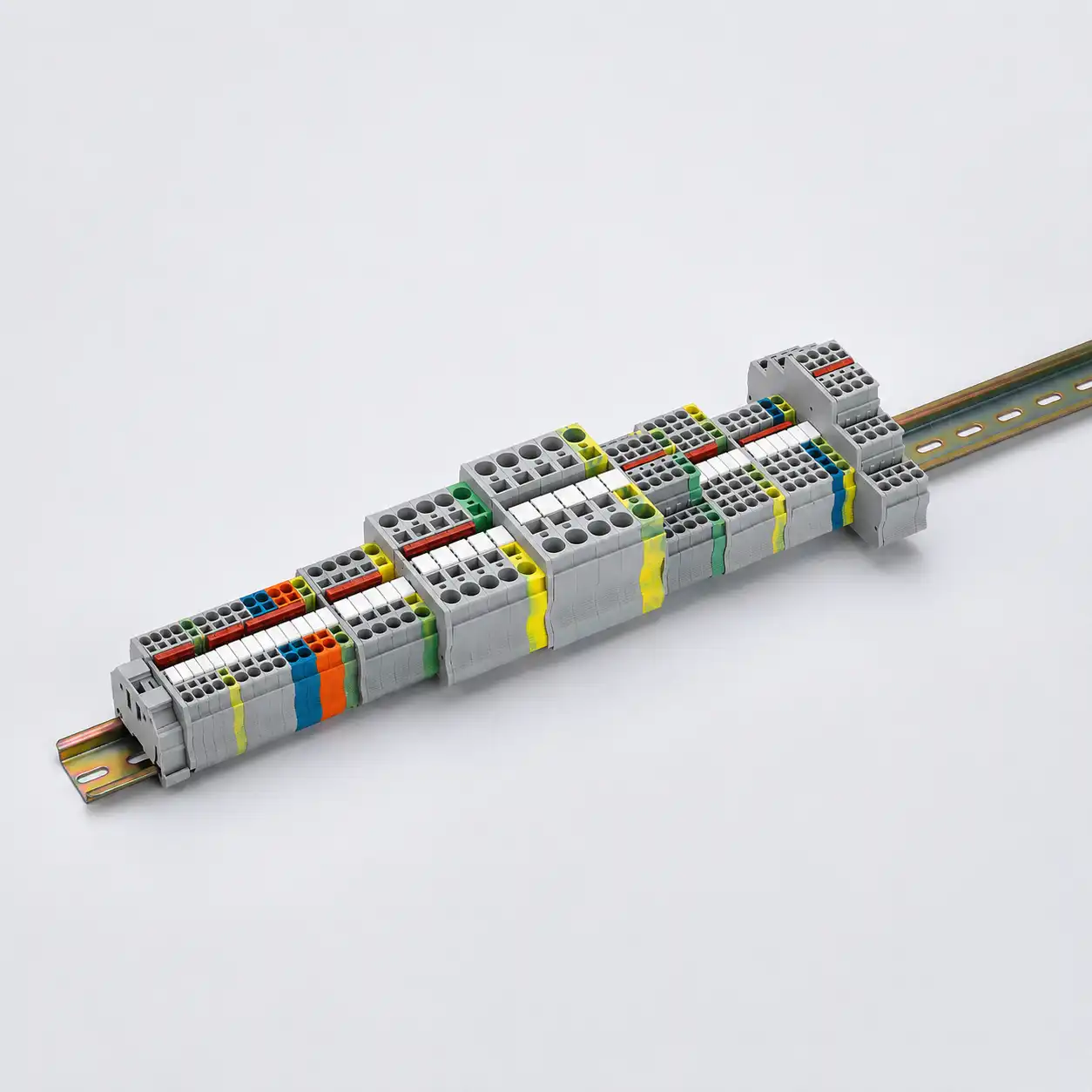
SENTOP product-family illustration. The image shows representative terminal and accessory formats; the released BOM and current product documentation control compatibility and ratings.
What should a buyer verify before release?
The five high-impact terminal block purchasing issues that are easy to miss are: using ratings without their declared conditions, assuming a conductor will fit, treating accessories as interchangeable, accepting incomplete approval or traceability evidence, and buying for initial installation without planning maintenance or supply continuity.
The practical remedy is to purchase a complete terminal-strip system. The purchase record should connect every terminal position to its circuit function, conductor, exact catalog number, accessory set, required evidence and service plan. A base-block quantity plus a generic description such as “2.5 mm² DIN terminal” is not enough to reproduce the engineered strip.
These five issues are a buyer’s risk framework, not a statistical ranking. Product documentation, the applicable panel standard, project specifications and qualified engineering review remain controlling.
Buy the terminal strip, not isolated blocks
A usable assembly combines the electrical terminals with the mechanical, safety, identification and service parts that make the design repeatable.
Functional terminals
Feed-through, PE, neutral, multi-level, disconnect, test, fuse or component terminals must match the circuit map. Color alone does not establish function.
Rail and retention
Specify the permitted rail profile, material, length, end clamps and mounting arrangement. A PE function requires a documented terminal-to-support and bonding system.
End and separation parts
Include end plates, partitions, separators and covers wherever the product instructions or completed-assembly assessment requires them.
Potential distribution
List every fixed or pluggable bridge by exact order code, pole count and location. Do not copy terminal current data onto a jumper without its own evidence.
Identification
Freeze marker material, print method, carrier, numbering data and orientation so assembly, drawings and field troubleshooting use the same identifiers.
Test and service items
Add test plugs, disconnect or fuse plugs, spare terminals and replacement consumables that maintenance will need—plus storage and revision rules.
Standards define scope and tests; they do not create interchangeability. IEC 60947-7-1:2025 covers specified terminal blocks and test-disconnect terminal blocks for round copper conductors within its scope. The standard’s voltage limits are not the rated voltage of every covered product, and its scope does not make two manufacturers’ parts or accessories interchangeable.
Ratings are quoted without their conditions
A purchasing line that records only current and voltage can detach a declared value from the conductor, test arrangement, insulation-coordination or fault-current conditions that make it meaningful.
| Claim on the request | What can be missing | What the buyer should retain |
|---|---|---|
| Rated current | Rated cross-section, rigid or flexible conductor, temperature-rise test arrangement, adjacent heat sources, grouping and bridge limitations. | The exact product data row, conductor schedule and design derating or thermal review used by engineering. |
| Rated voltage | Clearance, creepage, rated impulse voltage, insulation-material group, pollution degree and the applicable wiring or system context. | The declared product rating plus the insulation-coordination assumptions used for the completed panel. |
| Short-circuit claim | Confusion between IEC short-time withstand current, North American SCCR and a protective device’s interrupting rating. | The applicable evaluation method, exact component evidence, voltage, conductors, OCPD and installation conditions. |
| PE capability | Rail profile and material, fixing interface, rail bonding, mounting hardware and the completed protective-conductor path. | The declared PE terminal, permitted support and bonding arrangement as one controlled system. |
Do not convert a product headline into a panel claim. A terminal’s normal current rating does not determine the completed panel SCCR, enclosure IP rating or compliance. For a North American industrial control panel, establish SCCR under the applicable UL 508A method and ensure the marked panel rating is suitable for the available fault current at the supply point.
Why accessories need their own ratings: Phoenix Contact’s official UT 6 example publishes different current information for the base terminal and its bridge arrangement. The lesson is not to reuse those particular values for another part; it is to preserve the exact terminal–conductor–accessory relationship behind every claim.
The conductor is assumed to fit and terminate
“2.5 mm² terminal block” hides the wire material, construction, preparation and number of conductors. A clamp can accept one combination and reject another that carries the same nominal cross-section.
Cross-section or AWG
Record every minimum and maximum conductor actually assigned to the clamping point; do not rely on the broad family range.
Material
IEC 60947-7-1 addresses copper conductors. Aluminum needs a terminal expressly declared for aluminum or Al/Cu use and the manufacturer’s instructions.
Construction
Separate rigid, stranded and flexible conductors. A data sheet can publish different limits for each construction.
Preparation
Verify bare wire, ferrules with or without plastic collars, TWIN ferrules and any permitted special preparation as distinct cases.
Termination method
Freeze strip length, torque or actuation method, insertion direction, tool access and any required ferrule or crimp process.
Conductors per clamp
Use two conductors in one clamping point only when the exact documentation permits that conductor combination and size. Physical fit is not approval.
Best buying practice: attach a conductor schedule to the RFQ and sample the proposed terminal with the project’s actual conductors, ferrules and tools before approving an alternate. The sample check complements—not replaces—the product documentation and engineering decision.
Accessories are treated as universal
Manufacturers may standardize selected accessories across a defined system, while other parts remain terminal-specific. Apparent fit, shared pitch or matching color is not an engineering compatibility record.
Confirm rail profile, terminal geometry, required end closure and mounting direction.
Release evidence: exact compatible-product listing and strip position.
Check system, pitch, pole count, cuttable or fixed form, current/voltage data and protection against unintended potentials.
Release evidence: bridge order code, terminal relationship and potential-group drawing.
Verify marker groove, material, printable area, carrier and printing system—not merely visual width.
Release evidence: marker BOM plus controlled numbering file.
Confirm the designated disconnect zone, plug function, ratings, component or fuse interface and safe operating instructions.
Release evidence: base terminal, plug and replaceable-item relationship.
Check where separation, touch protection, end closure, voltage segregation or assembly assessment requires them.
Release evidence: quantity and exact placement on the terminal-strip drawing.
Ingress protection and touch protection are different claims. Do not transfer an enclosure IP rating to a bare terminal block. Access-probe results such as IPXXA or IPXXB concern access to hazardous parts; they do not establish the completed enclosure’s dust or water ingress protection.
Approvals, traceability and substitutions remain too vague
Descriptions such as “IEC approved,” “UL terminal block” or “same as” do not identify what was evaluated, which conditions apply or whether the shipped part matches the engineered record.
Exact identity
Record manufacturer, full order code, terminal family, variant, color where functional, connection technology and current revision or series. A shortened code can hide a materially different product.
Applicable evidence
Request the data sheet, applicable standard, certification body or UL file, ratings and conditions of acceptability that identify the exact part and intended market.
Traceable supply
Define label, lot, packaging, country-of-origin or certificate requirements only where the project needs them, then make incoming inspection capture the same record.
Change authority
Name who can approve an alternate, what comparison package is required and how drawings, BOMs, work instructions and stock are revised after approval.
Use precise conformity language. IEC publishes standards and conformity-assessment frameworks; it does not “approve” an individual terminal block. A UL Recognized Component is evaluated for use within a larger product under stated conditions. Component evidence supports the panel design but does not by itself certify the finished panel, establish its SCCR or prove suitability for every jurisdiction.
A substitution is a new engineering decision. Similar color, rail foot, cross-section or headline rating does not prove equivalence. A configurator can support the BOM, but the released project BOM, drawings and approval record remain authoritative.
The order is optimized for installation, not lifecycle
The lowest initial line-item cost can produce a strip that is slow to commission, difficult to troubleshoot or dependent on accessories nobody planned to stock.
| Lifecycle need | Question before purchase | Control to place in the BOM or project record |
|---|---|---|
| Identification | Can every wire, terminal, potential group and field destination be read in the installed orientation? | Marker material, numbering file, printer or service source, carrier and spare labels. |
| Testing | Can commissioning isolate or measure the intended circuit without improvised disassembly? | Exact test/disconnect points, plugs, safe method boundary and retained commissioning record. |
| Spare capacity | Does the strip have documented physical, electrical and identification capacity for credible changes? | Defined spare ways by function—not an arbitrary percentage—and reserved drawing positions. |
| Replacement | Can maintenance obtain and correctly identify the exact terminal, fuse, plug, marker and end hardware? | Service BOM, approved equivalents if any, storage location and change-control owner. |
| Supply risk | Which proprietary bridges, markers, tools or functional plugs could stop assembly or repair? | Lead-time review, minimum stock, lifecycle status, alternate strategy and obsolescence trigger. |
The lifecycle-ready decision is specific. It identifies what is stocked, where it is used, which revision is valid and who may change it. “Keep some spares” is not a service plan.
Five steps from drawing to controlled purchase
A vertical workflow keeps all five stages visible without turning the final stage into an isolated card.
Map every terminal position to a function
Start with the electrical drawing. Identify circuit, potential, wire number, field destination, PE/neutral role, disconnect or fuse function and required test access for each position.
Attach electrical and conductor data
Add voltage/current context, fault-duty method, conductor material, cross-section, construction, ferrule practice, quantity per clamp, strip length and environmental or thermal conditions.
Build the complete strip BOM
Freeze exact base terminals, PE/neutral/function blocks, rail, end clamps, end plates, partitions, bridges, markers, test items, covers and spares with quantities by strip.
Set compliance, traceability and substitution controls
Specify the evidence package, intended market, exact-order-code traceability, incoming records and the engineering authority and comparison data required for any alternate.
Validate assembly and lifecycle readiness
Review the strip drawing, sample critical conductor/accessory combinations, confirm tool and marker availability, set spare stock and release only the revision that passed the gate.
Why a familiar “2.5 mm² equivalent” can break the strip
The failure often appears outside the headline electrical rating.
The proposed alternate
A supplier offers a lower-cost 24 VDC feed-through terminal with the same nominal conductor class, current headline, color and rail width. The base block appears interchangeable.
During assembly, the marker system differs, the released cross-connection does not engage, the selected ferrule collar will not enter as planned and the power-distribution bridge has no documented rating for the alternate.
The correction: pause release and compare the complete terminal-strip system—not just the base block.
Identity and conductors
Compare full order code, connection technology, every conductor construction, ferrule style, strip length and number per clamping point.
Mechanical system
Verify rail interface, width, level, end hardware, marker system, tool access and the installed dimensions in the actual enclosure.
Electrical accessories
Check bridge, test, disconnect, fuse and protective parts against official compatible-product records and their own rating conditions.
Evidence and change
Review applicable approvals, market conditions, drawings, work instructions, stock impact and written engineering authorization before revising the BOM.
Seven records that make a terminal-block order verifiable
Use this as a release checklist. The same records should drive quotation comparison, purchase approval and receiving inspection.
Issue the exact strip sequence, order codes, quantities, rail/end hardware, accessories, markers, covers and spares by panel or assembly.
List function, voltage/current context, conductor material, cross-section/AWG, construction, preparation, quantity per clamp and strip length.
Preserve current official documents and compatible-product records for terminals, bridges, functional plugs, markers, rail and end parts.
Identify intended market, applicable standard, certificate or UL file, exact catalog number, ratings and conditions—without implying finished-panel approval.
Require a side-by-side technical comparison, affected drawings/BOMs, sample validation where justified and named engineering approval before use.
Check order code, quantity, package and lot data where required, visible damage, accessory completeness and evidence revision against the released record.
Define spare terminals and proprietary accessories, storage, replenishment, lifecycle monitoring, approved alternatives and the owner of future changes.
Acceptance should be reproducible. If the buyer cannot identify the same exact product, compatible accessories and evidence at receiving that engineering used at release, the purchasing record is incomplete.
Terminal block purchasing questions
What is the first thing to check when buying terminal blocks?
Start with the terminal-strip drawing and conductor schedule, not a generic block description. Each position needs a circuit function, exact conductor combination, connection method and required accessories before a defensible product can be selected.
Can I substitute a terminal with the same current rating?
Not on current rating alone. Compare the exact conductor matrix, connection technology, dimensions, rail and end hardware, bridges, markers, test or function accessories, rating conditions, approvals and lifecycle impact. Use the project's named engineering approval process.
Which accessories should a terminal-strip BOM include?
Depending on the design, include rail, end clamps, end plates, partitions, bridges, markers and carriers, covers, test plugs, disconnect, fuse or component plugs and spares. Confirm each item through the exact terminal system's compatible-product documentation.
Why does conductor type matter if the cross-section is correct?
Rigid, stranded and flexible conductors, and bare, ferruled or TWIN-ferrule preparations, can have different permitted ranges. Collar dimensions, strip length, tooling and the number of conductors per clamp can also change acceptance.
Does a component approval prove the finished panel complies?
No. Component evidence supports the design under stated conditions, but final-panel compliance also depends on the complete assembly, enclosure, wiring, SCCR method, intended market and other applicable requirements.
How should short-circuit suitability be verified?
Use the method applicable to the finished equipment and jurisdiction. Do not mix IEC short-time withstand current, North American SCCR and an OCPD interrupting rating. Retain exact component evidence and every stated voltage, conductor, OCPD and installation condition.
What labels should appear on the purchase order?
Use the full manufacturer order code and required variant, plus project line, panel or strip reference. Add lot, country-of-origin, certificate or packaging requirements only where needed, and define what receiving must record.
What terminal block spares should a panel builder stock?
Stock the exact functional terminals and proprietary bridges, markers, plugs, fuses or end parts whose absence could stop assembly or service. Set quantities from installed population, failure or consumption history, lead time, criticality and lifecycle status, not an arbitrary universal percentage.
Standards and manufacturer evidence
These references establish technical boundaries and examples. Current documents for the exact purchased product remain controlling.
- IEC 60947-7-1:2025 — terminal blocks for copper conductors
- IEC 60947-7-2 — protective-conductor terminal blocks
- IEC TS 60947-7-5 — terminal blocks for aluminum conductors
- UL Solutions — determining machinery SCCR
- UL Solutions — Component Recognition and conditions of acceptability
- Weidmüller — electrical testing of terminal blocks
- Weidmüller — mechanical testing and touch protection
- Phoenix Contact UT 6 — exact-product conductor, current and bridge data example
- Phoenix Contact — terminal block accessories
- Phoenix Contact UBAL 95 — declared aluminum/copper example
Turn the terminal list into a buildable, traceable strip
Send SENTOP your terminal-strip drawing, conductor schedule, target market and expected quantities. We can review the block family, accessories, evidence package and BOM boundaries before quotation.