
Terminal Block Temperature Rating Explained (With Chart)
A terminal block temperature rating is not automatically the maximum ambient temperature or a stand-alone current guarantee. Identify the exact field—operating range, temperature rise, material RTI, storage limit or another declared value—then match it to the real conductor, loaded positions, mounting and enclosure conditions.
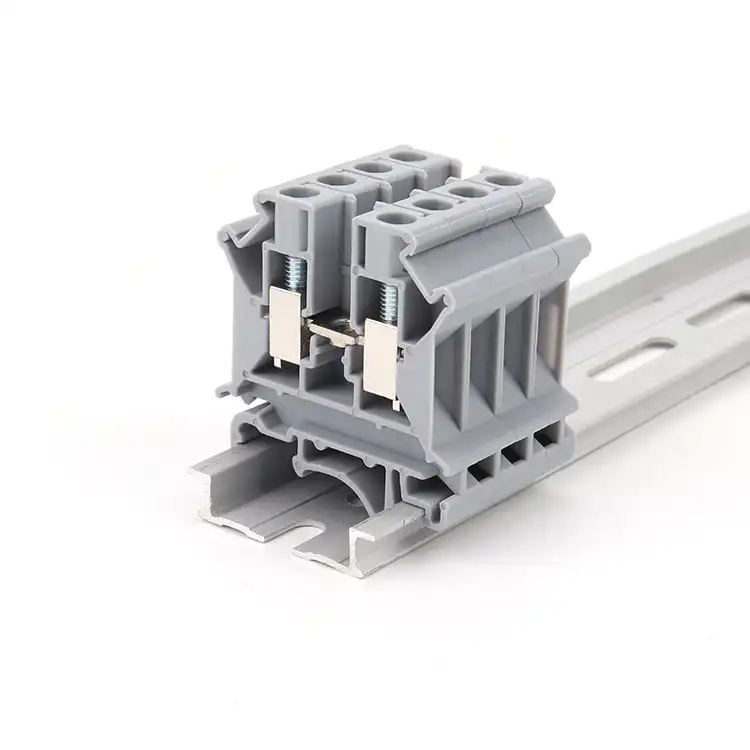
Terminal blocks do not have one universal temperature number. Keep operation, storage, assembly, material RTI and temperature-rise data separate, then apply the exact model’s limits to the actual conductor, loaded positions, accessories and local enclosure ambient.
The label beside the number decides what it means
A value such as 110 °C, 130 °C or 45 K is incomplete without its field name and test basis. It may be an operating ambient, polymer property, storage condition, assembly range or standardized temperature rise. Combining them into one “thermal ceiling” is invalid.
Start with the worst credible cabinet temperature at the terminal location. Add the real current and duty, conductor, adjacent loaded positions, accessories, mounting density and airflow. Every component and end-equipment limit must still be met.
Six fields often mistaken for one terminal block temperature rating
Use this chart as a field-name decoder. It deliberately replaces generic “temperature by material” tables that cannot represent a finished product.
Ambient temperature—operation
The stated surrounding-air range for an operating product. Read every note, especially whether the range includes self-heating or has separate short-term conditions.
Storage and transport
Non-operating logistics conditions. This range may be narrower than operation and must not be used as a current-carrying limit.
Assembly and actuation
The temperature range for mounting, inserting conductors, operating a spring or push button, or otherwise manipulating the connection.
Temperature rise
The increase caused by current in a defined laboratory arrangement. It is a difference, normally expressed in kelvins, not an absolute operating temperature.
Material RTI
A property-specific long-term thermal-aging index for a recognized polymer formulation. Electrical, impact and strength indices can differ by grade, thickness and color.
Other system limits
Wire insulation, bridges, fuse elements, plug/header interfaces, neighboring equipment and the end-product standard can control before the housing does.
One terminal block, six different thermal statements
Phoenix Contact PT 2,5 demonstrates why the field label matters. This third-party public example teaches the method; it is not a cross-reference or equivalence claim for a SENTOP model.
Phoenix Contact PT 2,5 · item 3209510
Public data checked August 4, 2026; retrieve the current document before release.
This operating ambient range includes self-heating; maximum short-term operation refers to RTI Elec.
A separate note permits −60 to +70 °C for no more than 24 hours.
Mounting and operating the connection have a narrower range.
UL 94 V0 is also listed. RTI, V0 and product operation remain separate fields.
The test passed; this is controlled type-test evidence, not a field allowance.
Separate UL Recognized 20 A rows use different conditions and must remain separate.
The lesson: 130 °C RTI does not create a 130 °C ambient rating, and a passed 45 K test does not let every installation add 45 °C to cabinet ambient. Keep each value with its own field and conditions.
An absolute limit and a rise value answer different questions
Copy the label, unit, measurement point, standard and configuration together. Do not turn a laboratory difference into a field operating limit.
Local ambient temperature
The surrounding air at the terminal location under the relevant operating condition. Measure or calculate the cabinet interior, including nearby heat sources and realistic duty.
Temperature rise
A difference between a measured point and the test ambient. A rise of 30 K has the same numerical size as a 30 °C difference; it is not an absolute 30 °C temperature.
Declared operating range
A manufacturer’s product field may include self-heating or other qualifiers. Read the wording before deciding whether the upper value applies to surrounding air, the component or a defined condition.
Lowest applicable limit
The conductor insulation, clamp, housing, bridge, fuse, plug interface, accessory, enclosure and end-equipment requirement must all remain within their own limits.
Current creates heat, but the installation decides where it goes
Resistive heating starts the process; the connection and installation determine the resulting temperature.
At unchanged resistance, increasing current by 20% changes I²R heating by 1.2² = 1.44, or 44%—not “nearly double.” Actual temperature is still not fixed by that calculation because resistance and heat dissipation can change with temperature and construction.
Current and duty
Continuous load, cycling, simultaneous circuits and harmonics produce different thermal conditions.
Connection resistance
Clamp design, conductor preparation, contamination and installation quality affect the interface. Follow exact model instructions.
Conductor path
Material, construction, cross-section, ferrule and length affect electrical and thermal behavior. Use the documented conductor row.
Heat rejection
Loaded neighbors, accessories, mounting, spacing, airflow, sunlight and nearby equipment influence local temperature.
If product data does not cover the proposed ambient, conductor, loaded-position arrangement or accessories, the thermal fit remains unresolved. Obtain documented application data or complete the required end-product evaluation.
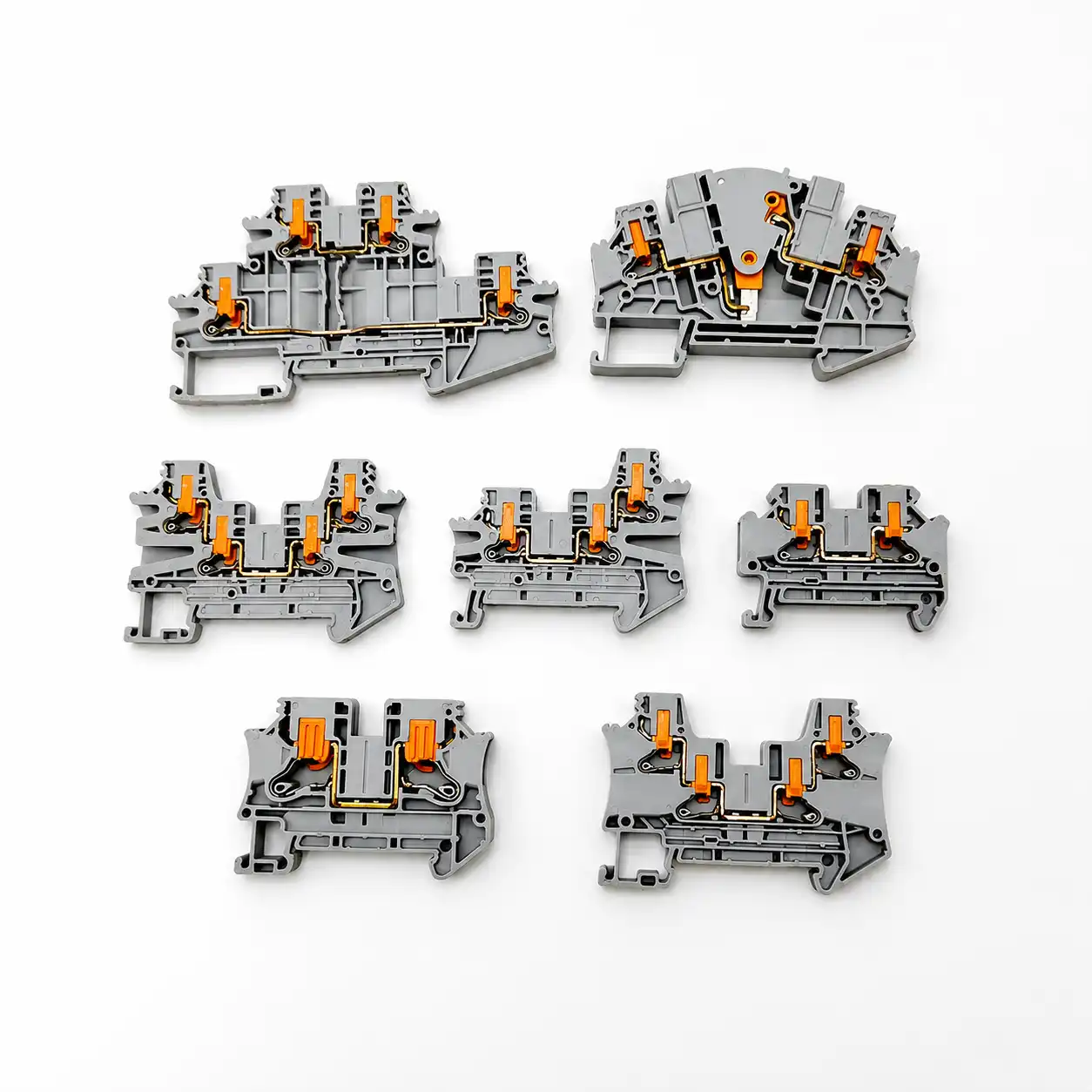
The published current belongs to a documented connection
A temperature decision is incomplete until the installed conductor and connection method match the data behind the current rating. Avoid transferring a curve or test result from another wire form, cross-section or number of loaded positions.
- Conductor row: match copper material, rigid or flexible construction, AWG or mm² and any special preparation.
- Ferrule permission: verify sleeve style, crimped cross-section, tube length and whether the exact terminal permits it.
- Strip length: use the model instruction so the conductive path is fully captured without exposed copper or insulation under the clamp.
- Screw connection: apply only the stated torque range to the correct screw with the specified procedure; there is no universal DIN-rail value.
- Spring or push-in: follow the exact actuation, insertion and conductor rules instead of assuming every screwless design behaves alike.
- Accessories: check bridges, fuse carriers, disconnect knives, plugs and headers for their own current and thermal limits.
How to read terminal block derating data correctly
Use an exact-model curve or written application limit. A generic percentage per 10 °C cannot represent conductor, pole count, contact system, accessories and enclosure conditions.
- Freeze the exact partRecord manufacturer, catalog number, revision, suffix and connection variant.
- Identify the curve familyConfirm which terminal, connector or assembled system the curve covers.
- Read every conditionMatch conductor, loaded positions, orientation, spacing and accessories.
- Use local ambientUse the worst credible temperature at the loaded terminal—not room or weather data.
- Read the permitted currentFollow interpolation instructions and never extend the published axes.
- Check the whole systemCompare wire, accessories, PCB, enclosure and approval limits.
RTI, UL 94 and product operation are not the same rating
PA or PA66 alone cannot establish an assembled terminal block’s continuous temperature. Use the exact formulation and product data.
RTI concerns long-term retention of a polymer property; operating range covers the assembled product; UL 94 covers small-specimen burning behavior. One does not upgrade another.
RTI Elec, Imp and Str
UL 746B property indices can differ by grade, minimum thickness and color.
UL 94 classification
V-0 or another class is a defined flammability test—not a continuous operating temperature.
Short-term material tests
Ball-pressure, glow-wire and needle-flame tests address specific behaviors, not the assembled product rating.
Finished component data
Housing, contacts, conductor, clamp and accessories work as a system. Use exact product documentation.
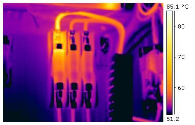
Thermography cannot identify polymer grade, RTI, flammability class or certification. Apparent temperatures depend on load, emissivity, reflection and viewing conditions.

Evaluate the terminal strip as an installed group
A laboratory value belongs to its test arrangement. A real rail can add bridges, fused terminals, disconnect elements, several conductor sizes and heat from nearby power supplies, drives or contactors. Record the assembled configuration instead of approving an isolated block photo.
- Local ambient: determine the worst credible air temperature beside the terminals while the enclosure is operating.
- Loaded positions: record which adjacent circuits carry current simultaneously and whether the source data uses the same arrangement.
- Accessories: include bridges, fuses, plugs, covers and test components with independent current or temperature limits.
- Heat sources: account for nearby devices, cable bundles, enclosure losses, airflow paths and solar loading without assuming a fixed temperature increment.
- Change control: reassess the thermal case when conductor size, spacing, accessory BOM, load profile, ventilation or enclosure changes.
Turn a catalogue value into a traceable installation decision
The goal is not to prove that a block “feels cool.” It is to show that the released model and installed configuration stay within documented limits at the defined worst case.
1. Define the worst case
Document local ambient, current and duty, conductor, loaded positions, accessories, mounting and airflow.
2. Match product evidence
Collect the exact datasheet revision, current basis, temperature fields, derating data and approval record.
3. Verify the representative build
If evidence is insufficient, test representative wiring, loading and enclosure conditions against a defined acceptance basis.
4. Release and control changes
Control the approved part, conductor and accessory BOM; re-evaluate relevant changes.
Type-test limits are evidence—not field derating formulas
Use the applicable standard, exact model and approval conditions. Different sample arrangements and measurement rules make a one-line “stricter standard” ranking misleading.
Current IEC scope
IEC 60947-7-1:2025, Edition 4 covers specified supported terminal blocks and test-disconnect terminal blocks for copper conductors, primarily for industrial or similar use.
Current UL scope
UL 1059, Sixth Edition covers terminal blocks rated 1500 V or less and explicitly says compliance alone does not establish suitability for every end product.
Published IEC test context
Phoenix Contact describes five rail-mounted terminals connected with rated-cross-section conductor loops at about 20 °C, with a maximum permitted rise of 45 K at the middle terminal.
Published UL test context
The same technical summary describes three horizontally adjacent terminals at 25 °C, with a maximum 30 K rise measured as close as possible to the terminal point. Conductor lengths also differ.
Collect nine inputs before approving a model
Use the same worksheet for every candidate so engineering, procurement and quality compare conditions instead of catalogue maxima.
- Exact identityManufacturer, full catalog number, variant, revision and source date.
- Local ambientWorst credible air temperature at the terminal location and how it was derived or measured.
- Electrical loadContinuous current, duty, simultaneous circuits and credible operating states.
- ConductorMaterial, rigid/flexible construction, AWG or mm², ferrule and preparation.
- Loaded arrangementNumber and position of adjacent loaded circuits, spacing, orientation and mounting density.
- Accessory pathBridges, fuses, disconnects, plugs, headers, covers and their independent limits.
- Temperature fieldsOperation, storage/transport, assembly/actuation, short-term notes, RTI and rise test data.
- Applicable evidenceTarget market, product standard, approval file, exact rating row and end-equipment conditions.
- Verification recordModel-specific curve or written limit, representative test if needed, accepted result and change-control trigger.
Abnormal evidence requires investigation—not a guessed temperature
These signs can have several causes. They do not reveal a past temperature or prove one component is at fault.
Discoloration or surface change
Heat, ultraviolet exposure, chemicals and contamination can all change a housing. Do not back-calculate a fixed historical temperature from color alone.
Deformation, cracking or brittleness
Any loss of insulation shape or mechanical integrity is a serious condition requiring the equipment’s approved isolation and assessment process.
Damaged conductor insulation
Glossing, flattening, cracking or fusion near a termination can indicate thermal, mechanical or chemical stress. Check the exact wire and equipment requirements.
Odor, soot or tracking marks
Do not continue normal operation to “see whether it gets worse.” Escalate under site electrical safety and incident procedures.
Unexpected thermal pattern
Compare equivalent points under comparable loads and conditions. There is no universal 10 °C action threshold for every terminal and application.
Electrical instability
Voltage drop, intermittent operation or protective-device activity can have multiple causes. Qualified personnel should diagnose the circuit using approved methods and limits.
Send the thermal case—not just “high temperature”
A useful model-matching enquiry defines the installed condition, what may change and which exact-model documents are required.
Send with your enquiry
- Existing model, datasheet, product photo, drawing or BOM
- Worst-case internal ambient at the terminal location and how it was determined
- Continuous current, duty, circuit voltage and simultaneous loaded positions
- Conductor material, rigid/flexible type, AWG or mm², ferrule and preparation
- Rail, PCB or panel mounting, spacing, orientation, enclosure and nearby heat sources
- Bridges, fuses, disconnects, plugs, covers, markers and other accessories
- Target market, required documents, quantity, packaging and destination
Require in the response
- Exact proposed catalog number, revision and documented deviations
- Operating, storage, assembly and actuation temperature fields with all notes
- Applicable current row, conductor condition and model-specific derating information
- Material, RTI and flammability data only where documented for the exact construction
- Compatible accessory list and any lower bridge, fuse or plug/header limit
- Applicable approval record, file or report and target-market conditions
- Sample plan, MOQ, price, packaging and confirmed model-specific availability
Convert thermal conditions into an exact-model request
SENTOP supplies multiple terminal block families and can review model numbers, photos, drawings or BOMs against current, voltage, conductor, mounting, environment and accessory requirements. Exact temperature data, materials, electrical ratings, certificate availability, MOQ, samples, stock and lead time must be confirmed for the selected model and order.
- Send the local cabinet ambient and load case with the existing model evidence.
- Keep every temperature field and approval row separate in the comparison.
- Mark conductor, loaded-position, accessory and mounting deviations explicitly.
- Release the sample, drawing, accessory BOM and document set to the same revision.
Need a model matched to your temperature conditions?
Send your worst-case enclosure ambient, electrical load, conductor, loaded positions, mounting, accessories, required documents, quantity and destination for an exact-model review.
Related thermal and specification resources
Terminal block temperature rating FAQ
What does a terminal block temperature rating mean?
It depends on the datasheet label and test basis. It may describe an ambient limit, an upper component temperature, a temperature-rise condition or another declared value. Read the exact model documentation.
Is the temperature rating the same as maximum ambient temperature?
No. Ambient temperature is the air surrounding the terminal, while current and connection resistance can raise the terminal above ambient.
How do I derate a terminal block at higher ambient temperature?
Use the exact model’s manufacturer-supplied derating curve or written application data. A universal percentage cannot account for conductor, loaded poles, mounting and enclosure conditions.
Can I use a 105°C-rated terminal block in a 100°C ambient?
Do not assume so. The connection also generates heat, and the conductor, contact system, accessories and installation may have lower limits.
Does every PA66 terminal block have the same temperature rating?
No. Resin grade, additives, molded thickness, component design, contact system and evaluated conditions can all differ.
Can tightening torque affect terminal temperature?
Connection quality can affect contact resistance and heating. For screw terminals, use the exact model’s conductor preparation and torque instructions with the specified tool and procedure.
Are UL and IEC thermal ratings interchangeable?
No. Verify the rating, standard, file or report and conditions for the exact catalog number required by the target market.
What information should I send SENTOP for temperature-based model matching?
Send the model or datasheet, worst-case enclosure ambient, continuous current, conductor type and size, loaded poles, mounting arrangement, connection method, target market, required documents, quantity and destination.
Primary sources used in this guide
- Phoenix Contact PT 2,5, item 3209510—official product data
- Phoenix Contact—IEC and UL terminal-block electrical test overview
- IEC 60947-7-1:2025 official scope
- UL 1059, Sixth Edition—Terminal Blocks
- UL 746B—Polymeric Materials, Long Term Property Evaluations
- UL Solutions—thermal aging tests and RTI
- UL Solutions—RTI Elec, Imp, Str and plastics-recognition abbreviations
- UL 94 official scope and end-use limitation
- Weidmüller—electrical testing and derating context
- BIPM SI Brochure—kelvin and degree Celsius
- Fluke—hot-spot detection, emissivity and comparative thermography
This guide is an educational selection framework, not an electrical design approval, certification decision, live-work procedure or universal maintenance threshold. Always use the exact current datasheet, manufacturer instructions, model-level approval evidence, applicable end-equipment requirements and qualified engineering review.
