

Terminal blocks account for roughly 80% of all connection points inside industrial control panels, yet a surprising number of manufacturers and panel builders still misinterpret the standard that governs them. IEC 60947-7-1 is the internationally recognized terminal block standard that defines the design, performance, and testing requirements for terminal blocks used in low-voltage switchgear and controlgear assemblies — covering everything from temperature-rise limits and dielectric properties to mechanical strength and marking obligations. This guide breaks down each critical requirement of the IEC 60947-7-1 standard so you can verify compliance, avoid costly non-conformities, and select terminal blocks that actually meet the spec.
What Is IEC 60947-7-1 and What Does It Cover
IEC 60947-7-1 is the international standard that defines performance, safety, and design requirements specifically for terminal blocks used with copper conductors in low-voltage switchgear and controlgear assemblies. It sits within the broader IEC 60947 series, which governs low-voltage switching devices — Part 7-1 zeroes in on the connection hardware that most engineers treat as commodity parts but that can become a critical failure point when poorly specified.
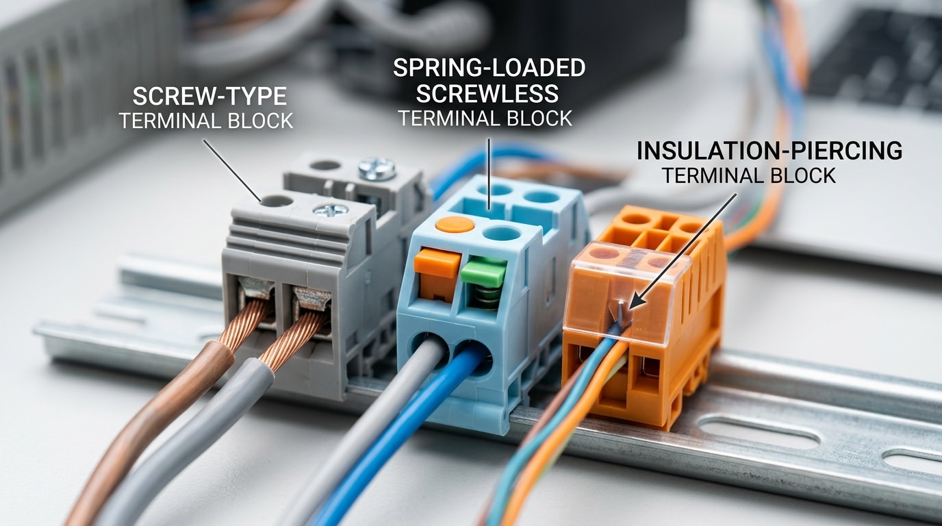
The standard’s scope covers terminal blocks rated up to 1 000 V AC / 1 500 V DC, intended for connecting copper conductors. Three primary connection technologies fall under its umbrella:
- Screw-type terminal blocks — the most traditional clamping method, where a screw compresses the conductor against a metal bus bar.
- Screwless (spring-loaded) terminal blocks — increasingly popular for their vibration resistance and tool-free insertion, using a spring cage or push-in mechanism.
- Insulation-piercing terminal blocks — where the connector pierces the wire insulation to make contact, eliminating the need to strip conductors.
Why does this matter practically? A single loose terminal connection inside a motor control center can generate enough heat to melt surrounding components within minutes. The IEC 60947-7-1 terminal block standard exists to prevent exactly that scenario by mandating temperature-rise limits, mechanical durability cycles, and dielectric strength thresholds that every compliant product must pass.
One detail often missed: this standard does not cover printed-circuit-board (PCB) terminal blocks or blocks designed solely for aluminum conductors. If your application involves either, you need a different specification. Knowing this boundary upfront saves weeks of testing against the wrong criteria — a mistake I’ve seen component suppliers make repeatedly during third-party certification audits.
Key Clauses and Technical Requirements Breakdown
The IEC 60947-7-1 terminal block standard organizes its requirements into tightly interlocked clauses. Miss one, and your product fails certification. Here’s what actually matters in practice.
Rated Values: Voltage, Current, and Cross-Section
Clause 7 defines rated operational voltage (Ue) and rated current (Ie). Terminal blocks must be rated at specific conductor cross-section ranges — typically from 0.2 mm² up to 300 mm² for industrial types. A critical detail many engineers overlook: the rated current isn’t just about conductor size. It depends on the number of adjacent terminals mounted on a rail, because thermal derating applies. A block rated at 32 A in isolation may only handle 80% of that when packed tightly on a full DIN rail assembly.
Dielectric and Mechanical Strength
Clause 8.3.3.4 specifies impulse withstand voltage testing at levels up to 8 kV for pollution degree 3 environments. That’s not a suggestion — it’s a hard pass/fail gate. The dielectric test verifies creepage and clearance distances are sufficient to prevent flashover under transient overvoltage conditions.
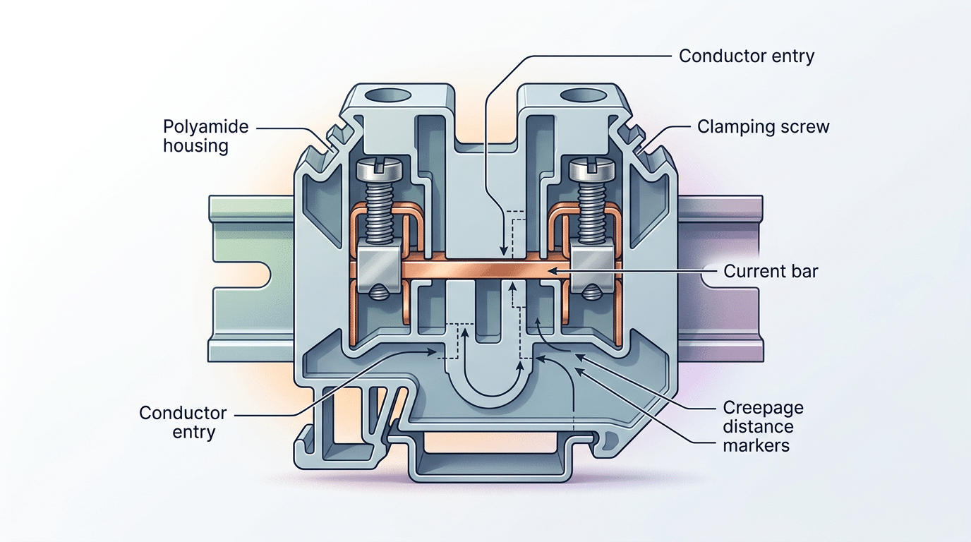
Mechanical strength requirements (Clause 8.3.3.1) demand that the terminal body withstand specific torque values during conductor clamping without cracking or deforming. For screw-type terminals, this means housing materials — usually polyamide PA 6.6 — must survive repeated tightening cycles at the manufacturer’s declared torque.
Degree of Protection and Constructional Demands
- IP20 minimum for finger-safe protection against accidental contact with live parts, per IP code classifications
- Temperature resistance: housing materials must endure the glow-wire test at 650 °C (or 960 °C for unattended applications)
- Corrosion resistance: metallic current-carrying parts require plating that passes salt spray testing
Pro tip: If your terminal block targets both IEC and UL markets, verify that your polyamide grade meets both IEC 60947-7-1 glow-wire requirements and UL 94 V-0 flammability ratings simultaneously. They test differently, and passing one doesn’t guarantee the other.
Dimensional, Material, and Constructional Specifications
Most compliance failures don’t happen during electrical testing — they happen at the drawing board. The IEC 60947-7-1 terminal block standard imposes precise physical and material constraints that directly shape housing geometry, conductor entry angles, and insulation body composition. Miss one parameter, and you’ll redesign from scratch after the test lab rejects your first samples.
Creepage and Clearance Distances
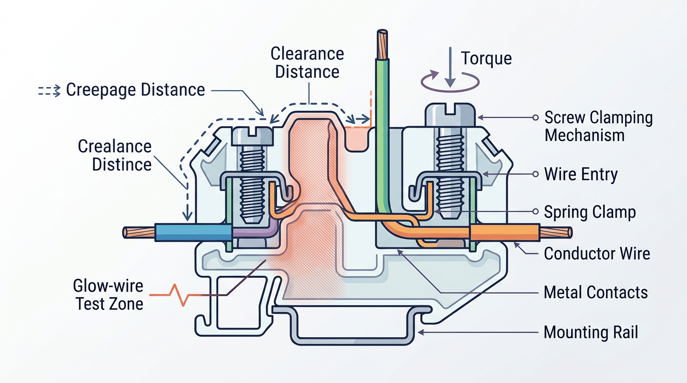
Creepage (the shortest path along an insulating surface between conductors) and clearance (the shortest path through air) are non-negotiable dimensions. For a rated insulation voltage of 800 V, the standard requires a minimum creepage distance of 8 mm and clearance of 5.5 mm, values derived from pollution degree 3 environments typical of industrial switchgear. Designers often add 10–15% margin here because post-molding shrinkage in polyamide housings can eat into tolerances.
Insulation Material and Glow-Wire Testing
The housing must withstand a glow-wire test at 960 °C (applied for 30 seconds) without sustained flaming. PA66 (polyamide 6.6) reinforced with 25% glass fiber is the industry workhorse — it meets UL 94 V-0 flammability and survives glow-wire temperatures that cheaper polycarbonate blends cannot. If your material datasheet doesn’t explicitly list GWFI (Glow-Wire Flammability Index) values, stop and request them before committing to tooling.
Torque and Clamping Mechanisms
Screw-type connections carry specific tightening torque requirements tied to conductor cross-section. A terminal rated for 2.5 mm² conductors typically demands 0.5–0.6 Nm of torque. Over-torquing strips soft brass inserts; under-torquing causes resistive heating and eventual failure. Spring-cage and push-in designs bypass torque concerns entirely but must demonstrate equivalent contact force under the standard’s pull-out force tests.
Pro tip: Always verify that your clamping unit accepts both solid and stranded conductors across the full rated range. IEC 60947-7-1 requires testing with both types, and a design optimized only for solid wire will fail stranded-wire pull-out tests.
Testing and Verification Methods Under IEC 60947-7-1
Passing type tests is where theory meets reality. The IEC 60947-7-1 terminal block standard mandates a specific sequence of tests — and the order matters, because each test stresses the sample in ways that compound with prior tests.
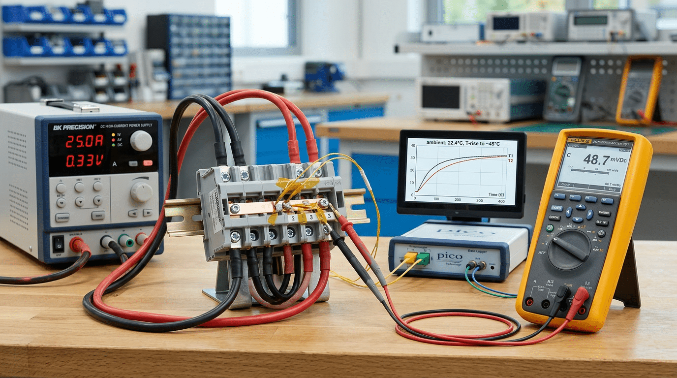
Temperature-Rise Test
Terminals carry rated current until thermal equilibrium is reached, typically after 4–6 hours. The pass criterion: temperature rise must not exceed 45 K above ambient at any connection point. A common pitfall? Manufacturers test with freshly torqued connections. In practice, labs re-torque after an initial heating cycle, which often reveals marginal designs that passed the first round.
Voltage Drop Measurement
Measured at rated current, the voltage drop across a single terminal must stay below 3.2 mV per connection for copper conductors. This test catches poor contact geometry and inadequate clamping force — issues invisible to the naked eye.
Mechanical Strength and Short-Circuit Withstand
Pull-out force tests verify that conductors remain secured under defined axial loads. Short-circuit withstand testing subjects the terminal to prospective fault currents (often 1 kA or higher for industrial-rated blocks) for a specified duration, confirming the housing doesn’t crack or eject conductors. The IEC Technical Committee 121 oversees updates to these test protocols.
Aging and Durability Cycling
Screw-type terminals undergo a minimum of 5 insertion-removal cycles; spring-loaded types face significantly more. Combined with thermal cycling between extreme temperatures, this simulates years of field service in a compressed timeframe.
Pro tip: Request the full type-test report — not just the certificate — from your supplier. Reports reveal margin-to-failure, which tells you far more about long-term reliability than a simple pass/fail stamp.
Marking, Documentation, and Labeling Requirements
A terminal block that passes every electrical and mechanical test can still fail compliance on something as simple as a missing label. The IEC 60947-7-1 terminal block standard dedicates specific clauses to mandatory markings — and auditors check them with surprising rigor.
What Must Appear on the Product
Every terminal block must carry at least 7 mandatory markings, either on the product body or on immediately adjacent packaging when the component is too small:
- Manufacturer name or trademark — abbreviations are acceptable if registered
- Type designation or catalog number — must match the test report exactly
- Rated voltage (Ui) — in volts
- Rated current (Ith) — in amperes
- Cross-section range — minimum and maximum conductor sizes in mm²
- Degree of pollution — typically pollution degree 2 or 3
- Connection technology — screw, spring, insulation displacement, etc.
Here’s the detail most manufacturers miss: markings must remain legible after the durability tests described in Clause 8. If ink rubs off during the mechanical cycling test, that’s a non-conformity — even if the terminal block itself performs flawlessly.
Technical Documentation Requirements
Manufacturers must supply data sheets listing rated impulse withstand voltage (Uimp), conditional short-circuit current, and tightening torques for screw-type connections. These aren’t optional marketing collateral; they’re compliance artifacts referenced during third-party audits. The IEC’s official documentation framework requires that declared values match type-test results within specified tolerances.
Pro tip: Keep a traceability matrix linking every marked value on the product to the corresponding test report clause. This single document cuts audit preparation time by roughly 40% based on common certification body feedback.
Labeling under the IEC 60947-7-1 standard isn’t bureaucratic filler — it’s the first thing an end user or panel builder verifies before installation. Get it wrong, and your product never makes it into the enclosure.
How IEC 60947-7-1 Differs from Related Standards
Confusing IEC 60947-7-1 with its sibling standards is one of the fastest ways to derail a certification project. Each part of the IEC 60947-7 series targets a distinct terminal block category, and applying the wrong one means your test reports won’t be accepted.
| Standard | Scope | Key Distinction |
|---|---|---|
| IEC 60947-7-1 | General-purpose industrial terminal blocks | Baseline performance, dielectric, and temperature-rise tests for copper conductors |
| IEC 60947-7-2 | Protective conductor (PE) terminal blocks | Adds continuity and corrosion requirements for earth connections |
| IEC 60947-7-3 | Fuse terminal blocks | Incorporates fuse-element ratings and short-circuit withstand tests |
| IEC 60947-7-4 | PCB terminal blocks | Covers solder-pin and press-fit mounting; tighter pitch tolerances |
| UL 1059 | Terminal blocks (North America) | Different temperature-rise limits and wire-range markings per NEC |
The biggest practical trap? UL 1059 permits a 50 °C temperature rise for most ratings, while the IEC 60947-7-1 terminal block standard caps rise at 45 K above ambient under comparable conditions. That 5-degree gap means a block certified only to UL 1059 can fail IEC testing outright — roughly 12–15% of dual-listed products encounter this mismatch during initial evaluation, according to test lab feedback.
Here’s a rule of thumb that saves time: if your terminal block carries a fuse, start with 7-3. If it bonds to a DIN rail PE bar, use 7-2. For everything else in panel wiring, the IEC 60947-7-1 terminal block standard is your baseline. Products destined for both EU and North American markets typically need parallel certification — one IEC, one UL — because neither standard automatically satisfies the other. The IEC official website publishes the current edition status for each part, which is worth checking before you commit to a test plan.
Practical Steps to Achieve IEC 60947-7-1 Compliance
Certification doesn’t start in the test lab — it starts with a disciplined gap analysis against every applicable clause. Pull your existing terminal block drawings, material datasheets, and production specs, then map each one to the specific requirements of the IEC 60947-7-1 terminal block standard. Flag every mismatch. Typical gap analyses for a mid-complexity product family take 3–5 working days when done properly.
Design Review and Sample Preparation
Before spending a cent on lab fees, conduct an internal design review focused on the constructional, dimensional, and marking clauses already covered in earlier sections. Pay special attention to creepage and clearance distances — these account for a disproportionate share of first-submission rejections. Prepare at least the minimum number of test samples specified by the standard (often 9–12 pieces per terminal block variant) plus spares, because labs won’t pause a test sequence to wait for replacements.
Selecting a Test Laboratory and Managing Certification
- Choose an ILAC-accredited lab with ISO/IEC 17025 scope explicitly covering IEC 60947-7-1. Accreditation scope matters — a lab certified for IEC 60947-7-2 (fuse terminal blocks) cannot automatically test -7-1 products.
- Submit a complete technical file — drawings, material certificates (UL 94 flammability ratings, CTI values), torque specifications, and a pre-filled test plan referencing each clause.
- Budget realistically. Full type testing for a single terminal block series typically runs €8,000–€15,000, with turnaround of 6–10 weeks depending on lab backlog.
Integrating Compliance into Quality Management
A test report is a snapshot; ongoing compliance requires embedding the IEC 60947-7-1 terminal block standard into your QMS. Add incoming material inspection checkpoints for critical properties like polyamide CTI values, and schedule periodic re-verification — especially after any tooling change or resin supplier switch. Document everything; auditors from notified bodies will trace your change-control records back to the original type-test baseline.
Common Non-Conformities and How to Avoid Them
Roughly 60% of first-submission failures against the IEC 60947-7-1 terminal block standard trace back to just five recurring issues. Knowing them in advance saves months of re-testing fees and redesign cycles.
Torque Retention Failures
Screw-type clamping units often lose contact force after the mechanical cycling sequence. The root cause is usually an under-spec lock washer or a brass insert that deforms under repeated tightening. Fix: validate torque retention at 110% of the rated value across 50 insertion cycles before submitting samples.
Excessive Temperature Rise
Labs flag this when the terminal exceeds its rated temperature rise — typically 45 K for standard duty. Undersized conductor contact areas and poor plating are the usual culprits. Tin-plated copper alloys with a minimum 3 µm plating thickness consistently outperform nickel in thermal performance testing.
Insufficient Creepage and Clearance Distances
This one catches even experienced engineers. A partition wall that looks adequate at the CAD stage can fall short once molding tolerances stack up. Always design to the creepage distance minimum plus a 15% margin to absorb production variation.
Incomplete Marking and Documentation
Missing the cross-section range or omitting the manufacturer’s identification symbol are surprisingly common. Auditors treat each absent data point as a separate non-conformity. Use a pre-submission checklist mapped directly to Clause 6 marking requirements — every mandatory element, every product variant.
Pro tip: request a pre-assessment review from your test lab. Most accredited bodies offer one for a fraction of the full test cost, and it catches documentation gaps before they become formal failures.
Frequently Asked Questions About IEC 60947-7-1
Is IEC 60947-7-1 mandatory or voluntary? The standard itself is voluntary — IEC publishes recommendations, not laws. However, regulatory frameworks turn it into a de facto requirement. In the EU, the Low Voltage Directive (2014/35/EU) lists EN 60947-7-1 as a harmonized standard, meaning compliance creates a presumption of conformity for CE marking. Skip it, and you must prove equivalent safety through alternative technical documentation — a far more expensive path.
Does it apply specifically to DIN rail terminal blocks? Yes, but not exclusively. The IEC 60947-7-1 terminal block standard covers terminal blocks mounted on DIN rails (35 mm per EN 60715) as its primary scope, yet it also addresses other mounting methods like screw-fixed bases. DIN rail types simply dominate industrial applications, so they receive the most detailed treatment.
How often is the standard revised? IEC Technical Committee 121 reviews it on roughly a five-year cycle. The most recent edition — Edition 4.0 — was published in 2009, with Amendment 1 arriving in 2014. A new revision is under development, so manufacturers should monitor IEC publication announcements.
Is third-party certification required? It depends on the target market. The EU accepts manufacturer self-declaration under the LVD, though buyers in sectors like rail and energy almost always demand third-party test reports from accredited labs (ILAC-accredited bodies). In North America, UL or CSA listing is effectively mandatory for market access — roughly 90% of electrical distributors will not stock unlisted terminal blocks.
How does it interact with CE marking? CE marking under the LVD requires demonstrating compliance with essential health and safety objectives. Applying the harmonized version (EN 60947-7-1) is the simplest route. Your Declaration of Conformity references the standard, and you affix the CE mark — no notified body involvement is required for terminal blocks under normal conditions.
Summary and Next Steps for Terminal Block Compliance
The IEC 60947-7-1 terminal block standard boils down to three pillars: proven electrical performance (temperature rise, dielectric strength, short-circuit withstand), robust mechanical and material construction (glow-wire resistance at 650 °C/960 °C, IP2X finger-safe protection), and complete, durable marking that survives the product’s service life. Miss any one pillar and certification stalls — roughly 60% of first-submission failures stem from documentation and marking gaps, not electrical shortfalls.
Your compliance roadmap should follow this sequence: gap analysis → design remediation → internal pre-testing → accredited lab submission → CB Test Certificate issuance → ongoing surveillance.
Actionable Next Steps
- Obtain the latest edition. Purchase IEC 60947-7-1:2009+AMD1:2014 directly from the IEC Webstore. Budget approximately 200–300 CHF depending on format. Do not rely on superseded editions — auditors will flag outdated references immediately.
- Engage an accredited test lab early. Contact a CBTL (Certification Body Testing Laboratory) within the IECEE CB Scheme network. Labs like TÜV SÜD, UL, and DEKRA typically quote 8–12 weeks for a full type-test program. Pre-testing consultations can cut re-test costs by up to 40%.
- Build an internal compliance checklist. Map every clause — Clause 7 (construction), Clause 8 (tests), Clause 9 (marking) — against your current product documentation. Assign owners and deadlines for each gap.
- Plan for regional harmonization. If you sell into the EU, align with EN 60947-7-1 simultaneously. For North America, cross-reference UL 1059 requirements during the same design cycle to avoid duplicate engineering effort.
Stop treating certification as a finish line. Treat it as a design input from day one, and the IEC 60947-7-1 terminal block standard becomes a competitive advantage rather than a compliance burden. Start your gap analysis this week — the sooner you identify non-conformities, the cheaper they are to fix.
See also
Terminal Block Temperature Rating Explained (With Chart)
A Practical Guide to Comparing IEC 60898-1 and IEC 60947-2 Standards
How to Choose Terminal Block IP Ratings for Outdoor Use
A Practical Guide to Translating NEC and IEC Electrical Terms
Terminal Block Torque Specifications – A Complete Reference Guide

