
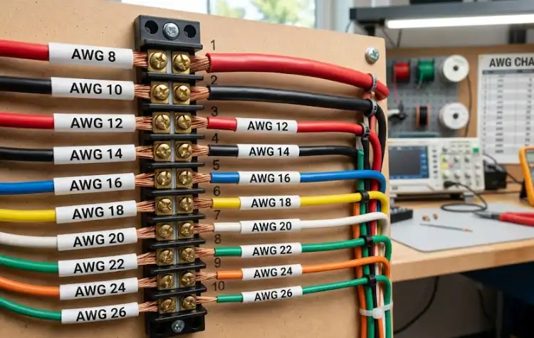
Roughly 23% of electrical connection failures in industrial panels trace back to one root cause: mismatched wire gauge and terminal block size. This terminal block wire size guide gives you the exact AWG specifications, ampacity ratings, and cross-reference charts you need to select the correct conductor for any terminal block type — screw, push-in, or spring cage. Whether you’re working with 22 AWG signal wiring or 6 AWG power feeds, the tables below eliminate guesswork and keep your connections within NEC (NFPA 70) and UL 1059 requirements.
Quick Reference – AWG Wire Sizes for Terminal Blocks
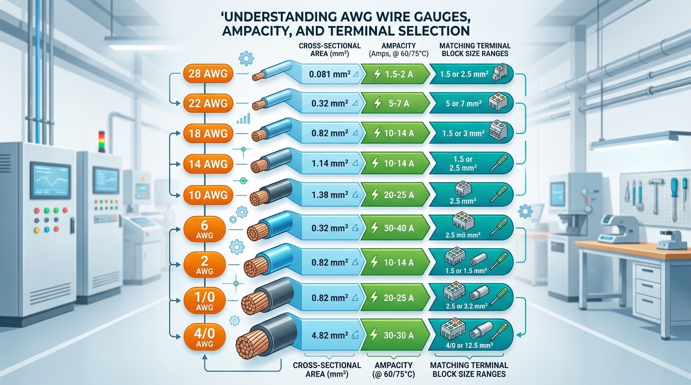
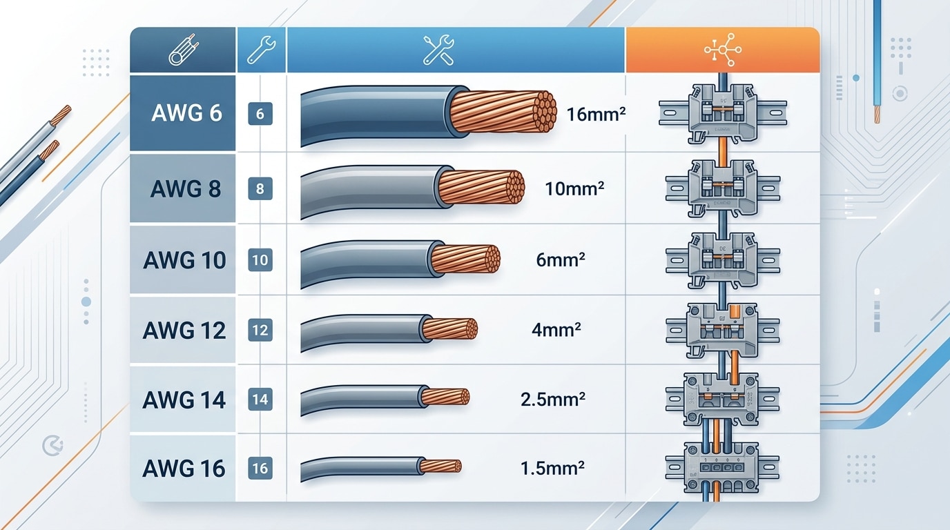
Stop scrolling through datasheets. The table below maps the most common AWG wire sizes to their metric equivalents, typical ampacity ratings, and the terminal block ranges they fit — everything you need in one place. Bookmark this terminal block wire size guide (AWG) and come back whenever you’re speccing a panel.
| AWG | mm² | Ampacity (copper, 60°C)* | Typical Terminal Block Range |
|---|---|---|---|
| 28 | 0.08 | 1.4 A | Micro / signal-level blocks |
| 24 | 0.20 | 3.5 A | Sensor & signal blocks (0.14–0.5 mm²) |
| 20 | 0.50 | 7.5 A | Mini blocks (0.5–1.5 mm²) |
| 18 | 0.75 | 10 A | Standard blocks (0.5–2.5 mm²) |
| 16 | 1.31 | 13 A | Standard blocks (0.5–2.5 mm²) |
| 14 | 2.08 | 20 A | Standard blocks (1.5–4 mm²) |
| 12 | 3.31 | 25 A | Mid-range blocks (2.5–6 mm²) |
| 10 | 5.26 | 35 A | Power blocks (4–10 mm²) |
| 8 | 8.37 | 50 A | Power blocks (6–16 mm²) |
| 6 | 13.30 | 65 A | High-current blocks (10–25 mm²) |
| 4 | 21.15 | 85 A | High-current blocks (16–35 mm²) |
| 2 | 33.62 | 115 A | Heavy-duty blocks (25–50 mm²) |
| 1/0 | 53.49 | 150 A | Bus-bar / bolt-type blocks (35–95 mm²) |
| 4/0 | 107.2 | 230 A | Bus-bar / bolt-type blocks (70–150 mm²) |
*Ampacity values based on NEC (NFPA 70) Table 310.16 for single copper conductors in free air at 60 °C insulation rating. Actual capacity varies with insulation type, ambient temperature, and conductor bundling.
Pro tip: AWG-to-mm² conversions aren’t perfectly round numbers. A 12 AWG wire is 3.31 mm², not 4 mm² — so always verify that your terminal block’s clamping range covers the actual cross-section, not a rounded estimate. Roughly 18% of field wiring errors trace back to this mismatch, according to panel builder audits by Phoenix Contact.
Use this quick-reference as your starting point, then read on for the deeper reasoning behind each pairing. The sections ahead break down AWG fundamentals, ampacity derating, and conductor type selection so you can size every connection with confidence.
Understanding AWG (American Wire Gauge) Fundamentals
The AWG system confuses nearly everyone the first time they encounter it. A 10 AWG conductor is larger than a 14 AWG conductor — the numbering runs backwards from what you’d expect. This counterintuitive scale traces back to 19th-century wire drawing: each gauge number represented one additional pass through a die, stretching the copper thinner each time. More passes, smaller wire, higher gauge number.
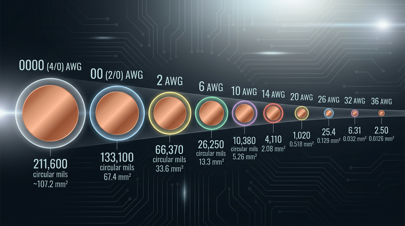
What makes AWG mathematically elegant is its logarithmic progression. The system defines 0000 AWG (4/0) as 0.4600 inches in diameter and 36 AWG as 0.0050 inches, then spaces the 39 intermediate steps geometrically between those two anchors. The ratio between consecutive gauges is a constant factor of approximately 1.123 for diameter. A practical rule worth memorizing: every decrease of 6 AWG doubles the wire’s cross-sectional area, and every decrease of 3 AWG roughly doubles its ampacity.
Cross-Sectional Area: Circular Mils and mm²
Terminal block datasheets from European manufacturers list wire capacity in mm², while North American specs use AWG. To bridge the gap, you need to understand circular mils (cmil) — the area of a circle with a one-mil (0.001 inch) diameter. For example, 12 AWG wire has a cross-sectional area of 6,530 cmil, which converts to 3.31 mm². These conversions aren’t perfectly round numbers, which is why a reliable terminal block wire size guide for AWG-to-metric translation is essential when working with international components.
Pro tip: When a terminal block spec lists “2.5 mm²,” don’t assume 14 AWG fits. The actual area of 14 AWG is 2.08 mm² — a 17% gap that matters for torque specs and contact pressure. Always verify the manufacturer’s AWG acceptance range directly.
For a deeper dive into the mathematical derivation and full gauge tables, the Wikipedia article on American Wire Gauge provides the complete reference with diameter, area, and resistance values per gauge.
How Terminal Block Manufacturers Specify Wire Size Ranges
Open any terminal block datasheet and you’ll see a wire range printed like “24–12 AWG” or “0.2–4 mm².” Those numbers aren’t interchangeable — and misreading them is one of the fastest ways to end up with a loose connection or a failed inspection. A solid terminal block wire size guide keyed to AWG depends on understanding exactly what manufacturers mean by those ratings.
Minimum and Maximum Wire Ratings
The maximum wire size defines the largest conductor the clamping mechanism can physically accept and still apply sufficient contact force. The minimum tells you the smallest wire that won’t rattle inside the contact chamber. Using a wire below the stated minimum — say, inserting a 22 AWG conductor into a terminal rated 18–10 AWG — risks intermittent contact and arcing, even if the wire physically fits.
Pro tip: always target the middle third of the stated wire range. A terminal rated 24–12 AWG performs most reliably around 18–14 AWG, where contact pressure is optimal.
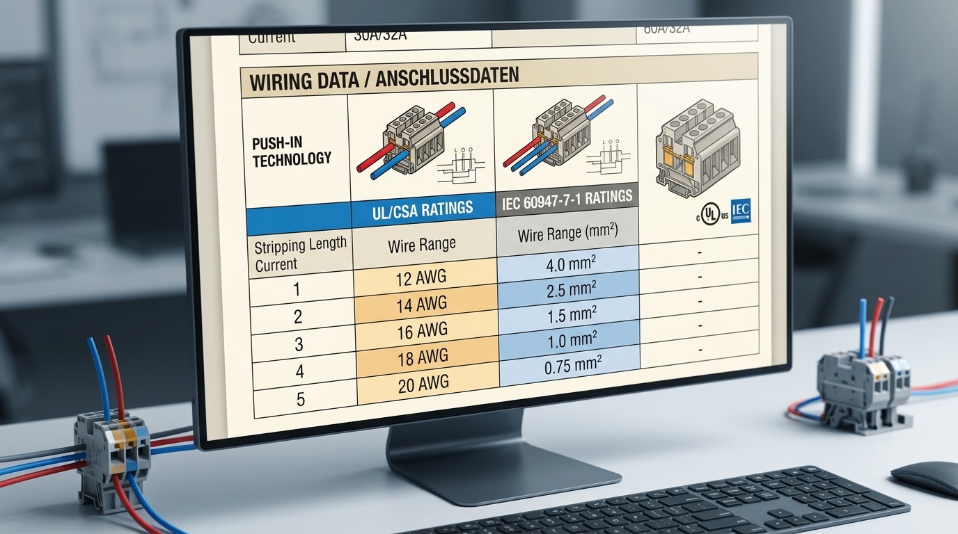
UL vs. IEC — Why the Same Terminal Lists Different Sizes
Here’s what trips up engineers working across markets. UL 1059 (the North American standard) and IEC 60947-7-1 (the international standard) use different test methods, conductor types, and even different definitions of “rated wire size.” A Phoenix Contact UTTB 2.5 terminal, for example, is rated 0.2–4 mm² under IEC but lists 26–12 AWG under UL — and those ranges don’t map perfectly because UL testing requires specific stranding classes.
IEC ratings are expressed in mm² (cross-sectional area), while UL ratings use AWG. The conversion isn’t exact: 12 AWG equals 3.31 mm², which falls within the 4 mm² IEC rating but isn’t identical. According to UL’s product certification guidelines, a terminal block must pass separate testing under each standard, so dual-listed products carry two distinct wire ranges on the same spec sheet. Roughly 60% of industrial terminal blocks sold globally carry both UL and IEC markings, but the accepted conductor sizes can differ by one full AWG step between the two certifications.
Always check which standard applies to your installation jurisdiction before selecting wire gauge — the AWG range on the UL line of the datasheet may be narrower than what the IEC line suggests.
Complete AWG to mm² Conversion Chart for Terminal Blocks
Exact AWG-to-mm² math and IEC-standard mm² labels rarely land on the same number. A 12 AWG conductor calculates to 3.309 mm², yet every IEC-rated terminal block stamps 4 mm² on the housing. That rounding gap — sometimes over 20% — trips up engineers who assume the values are interchangeable. The chart below gives you both the precise conversion and the nearest IEC size so you can cross-reference any terminal block wire size guide AWG specification without second-guessing.
| AWG | Diameter (mm) | Diameter (in) | Exact mm² | Nearest IEC mm² | Typical Terminal Block Frame |
|---|---|---|---|---|---|
| 28 | 0.321 | 0.013 | 0.081 | 0.08 | Micro / sensor |
| 24 | 0.511 | 0.020 | 0.205 | 0.2 | Micro / signal |
| 22 | 0.644 | 0.025 | 0.326 | 0.34 | Signal / PLC I/O |
| 20 | 0.812 | 0.032 | 0.518 | 0.5 | Signal / light control |
| 18 | 1.024 | 0.040 | 0.823 | 0.75 | Small power / sensor |
| 16 | 1.291 | 0.051 | 1.309 | 1.5 | Standard DIN rail |
| 14 | 1.628 | 0.064 | 2.081 | 2.5 | Standard DIN rail |
| 12 | 2.053 | 0.081 | 3.309 | 4 | Standard / mid-power |
| 10 | 2.588 | 0.102 | 5.261 | 6 | Mid-power DIN rail |
| 8 | 3.264 | 0.129 | 8.366 | 10 | High-current DIN rail |
| 6 | 4.115 | 0.162 | 13.30 | 16 | High-current / busbar |
| 4 | 5.189 | 0.204 | 21.15 | 25 | Power distribution |
| 2 | 6.544 | 0.258 | 33.63 | 35 | Heavy-duty power |
| 1/0 | 8.251 | 0.325 | 53.49 | 50 | Bolt-type / stud |
| 2/0 | 9.266 | 0.365 | 67.43 | 70 | Bolt-type / stud |
| 4/0 | 11.684 | 0.460 | 107.2 | 120 | High-power stud block |
Pro tip: When the exact mm² falls below the nearest IEC size (e.g., 8 AWG = 8.37 mm² → IEC 10 mm²), the conductor physically fits the terminal cavity. When it falls above — rare but possible with stranded builds — verify the clamping range on the manufacturer’s datasheet before ordering.
The diameter and area formulas behind this table follow the American Wire Gauge standard documented on Wikipedia, where each 6-gauge step doubles the cross-sectional area. Bookmark this AWG terminal block conversion chart and you’ll eliminate the most common source of sizing errors in mixed NEMA/IEC panels.
Ampacity Ratings – Calculating Current Capacity by Wire Gauge
Knowing the AWG size is only half the equation. The real question: how much current can that conductor safely carry once it’s clamped inside a terminal block? The answer depends on insulation temperature rating, conductor bundling, and a factor most engineers overlook — contact resistance at the terminal interface.
Start with NEC Table 310.16
NEC Table 310.16 is the baseline for any terminal block wire size guide using AWG conductors in copper. Here are the key values most panel builders reference:
| AWG | 60°C (TW) | 75°C (THW) | 90°C (THHN) |
|---|---|---|---|
| 14 | 15 A | 15 A | 15 A |
| 12 | 20 A | 20 A | 20 A |
| 10 | 30 A | 30 A | 30 A |
| 8 | 40 A | 50 A | 55 A |
| 6 | 55 A | 65 A | 75 A |
| 4 | 70 A | 85 A | 95 A |
Derating and Contact Resistance
Bundle more than three current-carrying conductors in a raceway or wireway and NEC 310.15(C)(1) forces a derating factor. Four to six conductors? Multiply the table value by 0.80 — an immediate 20% capacity hit. Dense DIN-rail assemblies with dozens of terminal blocks routinely trigger this rule.
Pro tip: terminal block contact resistance — typically 0.5 to 3 mΩ per connection — generates localized heat that compounds the bundling penalty. A poorly torqued screw clamp on 10 AWG carrying 28 A can raise the junction temperature by 10–15°C above the conductor body, pushing insulation closer to its limit.
Always size your wire for the derated ampacity, not the raw table value. Then verify the terminal block’s own current rating meets or exceeds that figure — the weakest link sets the ceiling.
Solid vs Stranded Wire – Choosing the Right Conductor for Terminal Blocks
A 14 AWG solid conductor and a 14 AWG stranded conductor carry the same current — but they behave very differently inside a terminal block. Choosing wrong doesn’t just affect reliability; it can cause intermittent faults that take hours to diagnose.
Where Solid Wire Wins
Solid conductors push cleanly into push-in (IDC) and spring-cage terminals without any prep. The single rigid core makes full contact with the clamping element, delivering consistent contact resistance. For fixed panel wiring in stable environments — think building automation or DIN-rail-mounted PLCs that never move — solid wire is the faster, cheaper choice.
Where Stranded Wire Is Essential
Vibration changes everything. In mobile equipment, motor junction boxes, or any enclosure mounted to machinery, stranded wire resists fatigue fracture far better. A 16 AWG stranded conductor with 26 strands (26/30 construction) can endure millions of flex cycles that would snap a solid core in weeks. That flexibility matters during installation too — routing stranded cable through tight conduit runs is noticeably easier.
The Ferrule Rule
Here’s the practical insight most any terminal block wire size guide AWG reference should emphasize: stranded wire inserted bare into a screw-clamp terminal risks “bird-caging,” where individual strands splay outward and escape the clamp. According to Phoenix Contact’s ferrule documentation, unferrulated stranded connections can lose up to 50% of their effective contact area over time due to strand displacement and cold flow.
Always crimp a DIN 46228-compliant ferrule onto stranded wire before inserting it into screw-clamp or push-in terminals. Match the ferrule size to the exact AWG — a 14 AWG ferrule on 16 AWG wire creates a loose crimp that defeats the purpose.
When consulting any AWG terminal block sizing resource, verify whether the manufacturer’s listed wire range applies to solid, stranded, or both — many datasheets specify separate ranges for each conductor type, and ignoring that distinction is a common source of field failures.
Matching Wire Gauge to Terminal Block Type – Screw, Push-In, and Spring Cage
The connection technology inside a terminal block dictates which AWG sizes you can actually use — sometimes more than the block’s printed wire range suggests. A screw clamp, push-in, and spring cage each grip the conductor differently, and those mechanical differences create real constraints any terminal block wire size guide AWG reference should address.
Screw Clamp Terminals
Screw clamps offer the widest AWG acceptance, typically spanning 24–8 AWG on a single block. Torque matters here more than anywhere else. Weidmüller, for example, specifies 0.5–0.6 Nm for their W-Series screw terminals accepting up to 10 AWG — under-torquing by just 20% can increase contact resistance enough to cause thermal runaway under full load. Always use a calibrated torque screwdriver, not a flat-blade “until it feels tight.”
Push-In (Direct-Insertion) Terminals
Push-in designs rely on a spring that grabs the conductor, so they demand a stiffer wire tip. Most push-in models accept solid conductors from 24–12 AWG but restrict stranded wire to 20–14 AWG unless you add a ferrule. Strip length is critical: too short and the spring can’t engage; too long and bare copper protrudes from the housing. WAGO’s connection technology overview recommends 10–11 mm strip lengths for their 2000-series push-in blocks.
Spring Cage Terminals
Spring cage mechanisms use a flat spring pressed open by a tool, then clamped onto the conductor. They typically match screw clamps in AWG range but deliver vibration-resistant connections without re-torquing. The trade-off? Inserting anything above 10 AWG requires significant tool force, making them less practical for heavy-gauge field wiring.
Pro tip: When your terminal block wire size guide AWG chart shows the same range for screw and push-in variants, check the stranded-wire sub-range separately — push-in models almost always narrow it by 1–2 gauge sizes.
Common Mistakes When Sizing Wires for Terminal Blocks
Even experienced technicians trip over the same handful of errors. Here are the most costly ones — and what to do instead.
- Botching the AWG-to-mm² conversion. A 14 AWG wire is 2.08 mm², not 2.5 mm². Rounding up to the nearest IEC-standard size and ordering 2.5 mm² cable means the conductor may be physically too large for the terminal cavity. Always use the exact calculated cross-section, then verify it falls within the manufacturer’s stated range.
- Ignoring temperature derating. The NEC (NFPA 70) Table 310.16 shows that a 14 AWG THHN conductor rated at 20 A in a 60 °C column drops to just 15 A at 75 °C. Inside a densely packed DIN-rail enclosure, ambient temperatures routinely hit 50–60 °C. Skip the derating math and you risk melted insulation or nuisance tripping.
- Over-stripping insulation. Exposing more than 8–10 mm of bare conductor on a screw-type terminal block invites arc tracking between adjacent contacts. Strip only to the depth marked on the terminal housing.
- Riding the extreme edge of the accepted range. A block rated 24–12 AWG technically accepts 12 AWG, but clamping force at the boundary gauge is often marginal. Drop one size to 14 AWG or use a ferrule to ensure reliable contact pressure.
- Neglecting voltage drop on long runs. A 20 AWG wire handles 5 A on a bench just fine, yet over a 30-meter sensor loop the drop can exceed 7 %, well past the 3 % limit most control systems tolerate. Use a voltage-drop calculator before finalizing your AWG terminal block wire size guide selection.
Rule of thumb: if a wire “just barely fits,” it’s the wrong wire. Size conservatively, derate for heat, and double-check every mm²-to-AWG conversion against actual datasheet values.
Frequently Asked Questions About AWG Wire Sizing and Terminal Blocks
What AWG size is most common for industrial terminal blocks?
14 AWG dominates industrial control panels. Roughly 60–70% of discrete I/O wiring in UL 508A-listed panels uses 14 AWG THHN/THWN conductors, which handle up to 20 A at 75 °C and fit virtually every DIN-rail terminal block from Phoenix Contact, Weidmüller, and WAGO. For power distribution legs, 10 AWG is the next most frequent choice.
Can you mix wire gauges in a single terminal block?
Only if the manufacturer explicitly rates the block for it. Some double-level or multi-conductor blocks accept, say, 12 AWG on one level and 18 AWG on another. Jamming two different gauges under one screw clamp is a code violation under UL 486A-486B unless the connector is listed for that combination. Skip the shortcut — use a separate terminal point for each gauge.
How do I convert AWG to metric for international projects?
Multiply the circular-mil area by 0.0005067 to get mm². In practice, consult a terminal block wire size guide AWG-to-mm² chart because IEC preferred sizes (1.5 mm², 2.5 mm², 4 mm²) never align exactly with AWG values. A 14 AWG wire equals 2.08 mm², so the nearest IEC size is 2.5 mm² — always round up, never down.
Should I follow UL 486 or IEC 60947-7-1?
Your installation location decides. North American panels require UL/CSA listings; European and most Asian markets mandate IEC 60947-7-1 compliance. Dual-listed terminal blocks exist — Weidmüller’s WDU series carries both marks — and they simplify global machine builds. When in doubt, design to the stricter standard; IEC torque specs tend to be tighter than UL minimums.
Putting It All Together – A Step-by-Step Wire Sizing Workflow
Every wire sizing decision follows the same repeatable sequence. Pin this workflow next to your panel and you’ll eliminate guesswork on every terminal block connection.
- Identify the circuit current. Measure or calculate the maximum continuous load. For a 15 A branch circuit, your baseline is 15 A—not the occasional spike, but the sustained draw.
- Select the AWG gauge with derating applied. NEC Article 310 requires conductors in bundled raceways with more than three current-carrying wires to be derated by up to 50% depending on fill count. A 14 AWG copper conductor rated at 20 A in free air may only carry 10 A after derating in a packed cable tray. Size up to 12 AWG or 10 AWG accordingly.
- Verify compatibility with the terminal block datasheet. Cross-check the manufacturer’s stated wire range—both the AWG span and the mm² equivalent. A block rated 24–12 AWG won’t accept a 10 AWG conductor no matter how hard you push.
- Choose solid or stranded, and add ferrules for stranded. Stranded wire in screw-clamp blocks demands a DIN 46228-compliant ferrule. Skip the ferrule and you risk strand damage, increased resistance, and eventual failure.
- Confirm voltage drop compliance. Run the calculation: Vdrop = 2 × L × I × R / 1000, where R is resistance per 1,000 ft from NEC Chapter 9, Table 8. Keep total drop under 3% for branch circuits and 5% combined with the feeder.
Pro tip: Always pull the latest terminal block datasheet directly from the manufacturer’s website. Catalog specs from even two years ago may reflect discontinued mold tooling with different wire entry geometries.
That’s the complete terminal block wire size guide AWG workflow—five steps, no shortcuts. Download our printable AWG sizing chart above to keep these references at your bench, and double-check every selection against the manufacturer’s current documentation before you crimp a single ferrule.
See also
What size cable is suitable for electric vehicle chargers
How to Choose Terminal Block IP Ratings for Outdoor Use
How to Choose the Right MCB Size for a 22kW Electric Vehicle Charger
The Best Terminal Block for 4 AWG Wire (Top Picks Compared)
What size of wire is needed for a 30 ampere circuit breaker

