
A single mismatched terminal block temperature rating can trigger insulation failure at just 15°C above the rated limit — a margin thinner than most engineers assume. According to UL 1059, every terminal block must carry a verified maximum operating temperature, typically ranging from 85°C to 150°C depending on the housing material and conductor size. This guide breaks down exactly what those ratings mean, how they’re tested under UL and IEC standards, and which material-to-application combinations actually hold up in the field — complete with a reference chart you can use for specification decisions right now.
What a Terminal Block Temperature Rating Actually Means
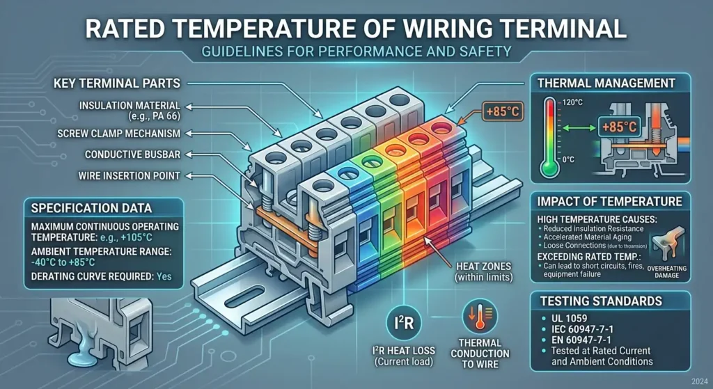
A terminal block temperature rating specifies the maximum continuous operating temperature the component can endure before its housing, insulation, or metal contacts begin to degrade. This isn’t a “burst” limit — it’s the sustained ceiling. Exceed it repeatedly, and you’ll see embrittled plastic, increased contact resistance, and eventually arc faults.
Most standard polyamide (nylon PA 6.6) terminal blocks carry a rating of 105 °C (221 °F), while high-performance ceramic or thermoplastic polyester types can reach 150 °C or higher. That 105 °C figure comes directly from IEC thermal class designations, where Class A corresponds to 105 °C maximum hotspot temperature. Misreading which temperature the rating actually describes is one of the most common specification errors in panel design.
Three Temperatures That Are Not the Same Thing
- Ambient temperature rating — the maximum surrounding air temperature the block is certified to operate in, typically 40 °C to 80 °C depending on the enclosure environment.
- Conductor temperature rating — the thermal limit of the wire insulation itself (e.g., THHN wire is rated 90 °C). This is a property of the cable, not the terminal block.
- Thermal class / overall temperature rating — the hotspot temperature the terminal block assembly (housing + contact + conductor) can tolerate continuously. This is the number printed on the datasheet.
Here’s the practical trap: a terminal block rated at 105 °C installed inside a panel with a 60 °C ambient temperature only leaves a 45 °C rise budget for I²R heating at the contact point. Overload the circuit by just 20%, and that temperature rise can nearly double — pushing you past the rating faster than most engineers expect. Always subtract your worst-case ambient from the block’s thermal class to find your real headroom.
What Determines a Terminal Block Temperature Rating
Five variables converge to produce the published terminal block temperature rating, and swapping just one — say, a different contact plating — can shift the ceiling by 30 °C or more. Understanding each factor explains why two blocks that look identical on the outside can carry wildly different thermal specs.
Housing Material Composition
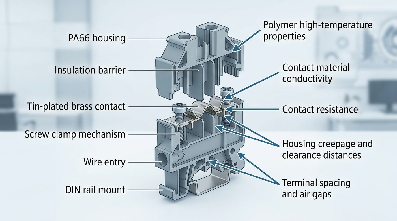
The polymer or ceramic body sets the upper boundary. A standard polyamide 6.6 (PA66) housing tolerates continuous use up to roughly 105 °C, while a polycarbonate variant may cap at 85 °C. Ceramic terminal blocks push past 300 °C. The resin’s Relative Thermal Index (RTI) — a UL-assigned value reflecting long-term thermal aging — is the single most influential number in the final rating.
Contact Plating and Conductor Compatibility
Tin-plated brass contacts behave differently from nickel-plated or silver-plated ones under sustained heat. Nickel plating resists oxidation above 150 °C where tin begins to degrade, directly raising the allowable operating range. Conductor gauge matters too: a block rated for 24–12 AWG will see higher localized heating when terminated with the smallest permitted wire because contact resistance increases.
Testing Methodology
Manufacturers don’t just pick a number. Certification bodies like UL apply the UL 1059 ball-pressure test, pressing a 5 mm steel ball into the housing at the rated temperature for one hour. If the indentation stays below 2 mm, the material passes. IEC 60947-7-1 uses a similar approach but adds a 1,000-hour thermal endurance cycle. These protocols explain why a block tested only to IEC may carry a different published figure than one tested to UL — even with identical materials.
Pro tip: Always check whether the rating references the housing RTI or the overall assembly rating. The assembly rating accounts for contact plating and insulation class together, and it’s almost always lower — sometimes by 20–25 °C.
Common Housing Materials and Their Thermal Limits
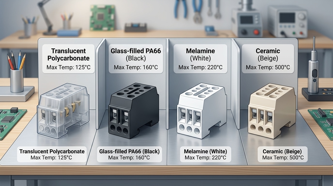
The housing material is the single biggest bottleneck on a terminal block temperature rating. You can spec premium copper alloy contacts and oversized conductors, but if the plastic body softens at 105 °C, that’s your ceiling — period.
Material-by-Material Breakdown
| Housing Material | Continuous Temp Limit | UL 94 Flame Class | Key Trade-Off |
|---|---|---|---|
| Nylon PA6 | ~105 °C | V-2 (standard), V-0 (FR grades) | Absorbs moisture → dimensional shift |
| Nylon PA66 | ~130 °C | V-0 (glass-filled) | Best cost-to-performance ratio |
| Polycarbonate (PC) | ~125 °C | V-0 | Impact-tough but UV-sensitive |
| Polyester PBT | ~150 °C | V-0 | Low moisture uptake; brittle at extremes |
| Melamine | ~170 °C | V-0 | Excellent arc resistance; fragile |
| Ceramic (Steatite) | ~1,000 °C+ | Non-combustible | Heavy, expensive, limited geometries |
Glass-filled PA66 dominates roughly 60–70 % of industrial terminal blocks because it hits the sweet spot: a 130 °C continuous rating, inherent V-0 flame retardancy when compounded with halogen-free additives, and enough mechanical strength for DIN-rail snap-fit designs.
Why UL 94 Flame Class Matters
A V-0 rating means a test specimen self-extinguishes within 10 seconds with no flaming drips — critical for panel-mount blocks near bundled wiring. V-2 allows flaming drips, which most OEMs reject for enclosed cabinets. If a datasheet lists only “UL 94 HB” (horizontal burn), treat that as a red flag for any application above 85 °C. The UL 94 flammability standard defines these classifications in detail.
Pro tip: When evaluating a terminal block temperature rating, always confirm the housing material’s Relative Thermal Index (RTI) on the UL iQ database — not just the generic polymer datasheet. RTI values are tested on the actual molded part thickness, and a 1 mm wall can rate 20 °C lower than a 3 mm wall in the same resin.
Terminal Block Temperature Rating Chart by Material and Standard
This is the reference table you came here for. It consolidates terminal block temperature rating data across four common block types, three housing materials, and the two dominant certification frameworks—UL 1059 and IEC 60947-7-1. Bookmark it.
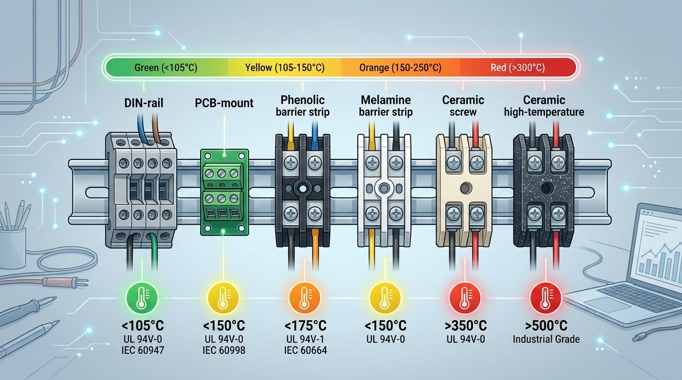
| Block Type | Housing Material | UL 1059 Rating | IEC 60947-7-1 Rating | Typical Use Case |
|---|---|---|---|---|
| DIN-rail | Polyamide 6.6 (PA66) | 105 °C (221 °F) | 110 °C (230 °F) | Industrial control panels |
| DIN-rail (high-temp) | Ceramic (steatite) | 300 °C (572 °F) | 300 °C+ (per manufacturer) | Furnace controls, kiln wiring |
| PCB-mount | PA66, glass-filled | 105 °C | 120 °C (with V-0 grade) | Power supplies, LED drivers |
| Barrier strip | Phenolic (Bakelite) | 150 °C (302 °F) | 130 °C | Legacy HVAC, motor junction boxes |
| Barrier strip | Melamine | 130 °C | 120 °C | General-purpose distribution |
| High-temp ceramic | Alumina / steatite | Up to 450 °C (842 °F) | Manufacturer-declared | Heating elements, thermocouples |
One detail that trips up engineers: UL and IEC numbers for the same block aren’t always identical. UL 1059 bases its rating on a ball-pressure test at the declared temperature, while IEC 60947-7-1 applies a glow-wire test at 650 °C or 850 °C depending on the application’s fire risk classification. A PA66 block can pass IEC’s 850 °C glow-wire test yet still carry only a 105 °C continuous rating—those are measuring different things entirely.
Pro tip: When sourcing globally, always confirm both the continuous temperature rating and the flammability class (UL 94 V-0, V-2, etc.). A block rated at 130 °C continuous but only UL 94 HB won’t pass muster in an enclosed panel where NEC Article 409 applies.
Roughly 80% of standard industrial terminal blocks on the market use PA66 with a 105 °C ceiling. That covers most panel environments—but “most” isn’t “all.” If your ambient already sits at 60 °C inside a sun-exposed enclosure, that 105 °C cap leaves you only 45 °C of headroom for I²R heating, which can vanish fast at full load.
UL and IEC Standards for Terminal Block Heat Resistance
Two regulatory ecosystems govern how a terminal block temperature rating gets validated: the UL framework dominant in North America and the IEC framework used across Europe, Asia, and most of the rest of the world. They test similar things — but not in the same way, and the differences matter when you’re sourcing globally.
UL 1059 and UL 94
UL 1059 is the primary standard for terminal blocks in the U.S. and Canada. It mandates a temperature rise test where the terminal carries rated current until thermal equilibrium is reached; the allowable rise is 50K above a 25°C ambient. UL 94 then classifies the housing’s flammability — V-0 being the most fire-resistant rating, meaning the flame self-extinguishes within 10 seconds with no dripping.
IEC 60947-7-1 and IEC 60998
IEC 60947-7-1 covers industrial terminal blocks and caps the permissible temperature rise at 45K above ambient — 5K stricter than UL 1059. IEC 60998 applies to connection devices in low-voltage installations and includes the glow-wire test, which presses a heated wire tip at 650°C (or 850°C for unattended applications) against the housing for 30 seconds. If the material ignites and the flame doesn’t extinguish within 30 seconds, it fails.
Key Differences That Affect Interpretation
- Ambient baseline: UL tests at 25°C; IEC typically references 35°C for industrial environments — so an IEC-rated block may actually tolerate higher absolute temperatures in practice.
- Rise limit: 50K (UL) vs. 45K (IEC). A terminal block rated under IEC has a tighter thermal margin built in.
- Fire testing: UL 94 uses a direct flame; IEC’s glow-wire test simulates overheated conductors — a more realistic failure mode for wiring accessories.
Practical tip: If your product ships to both markets, design to the stricter IEC 45K rise limit. Meeting IEC first makes UL compliance straightforward, but the reverse isn’t always true.
Understanding which standard backs a terminal block temperature rating prevents costly surprises during certification — especially when a datasheet lists only one standard and you’re exporting to a region that requires the other.
How Ambient Temperature Affects Current Capacity and Derating
A 30A terminal block isn’t always a 30A terminal block. That rating assumes a specific ambient temperature — typically 25°C in lab conditions. Raise the ambient to 50°C inside a sealed enclosure, and that same block may only safely handle 20A or less. This reduction is called derating, and ignoring it is one of the fastest paths to thermal failure in real panels.
Why Derating Happens
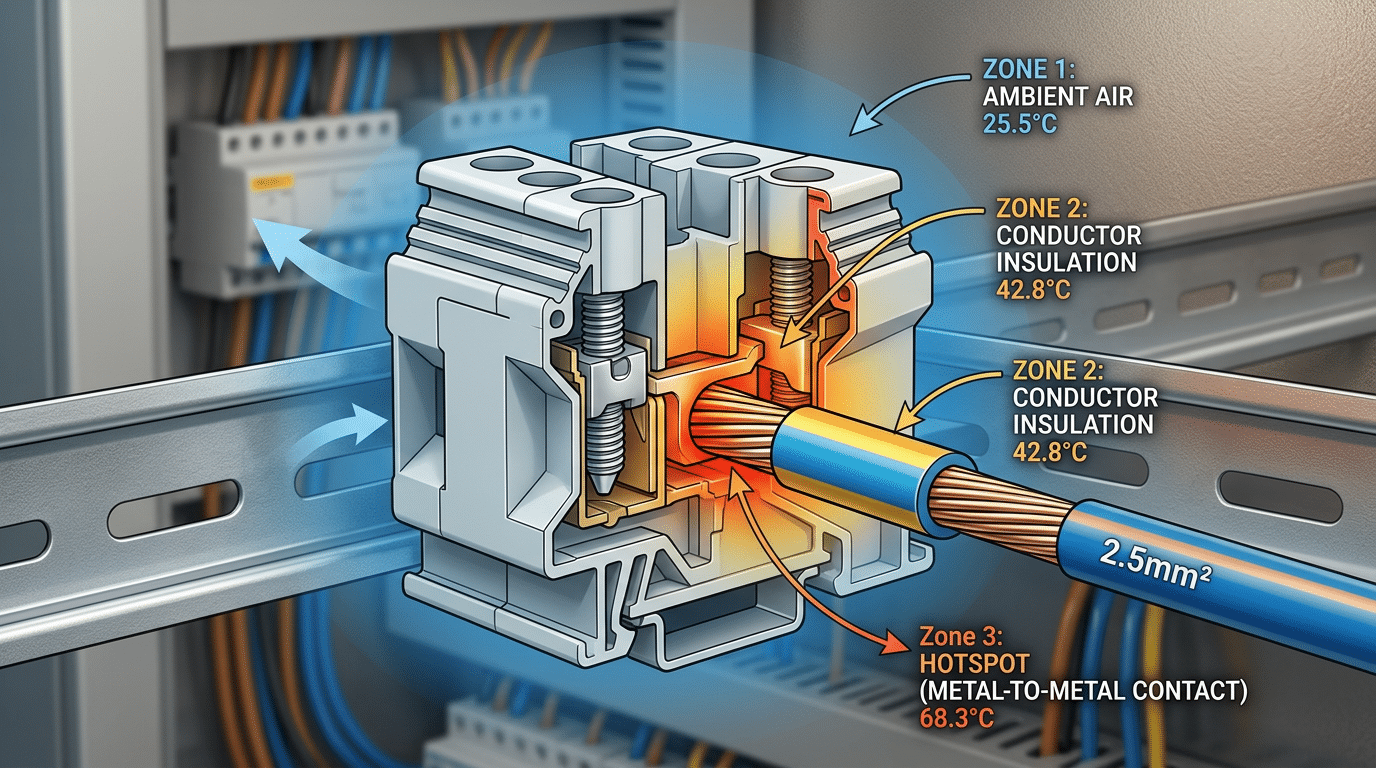
Every conductor and contact point generates resistive heat (I²R losses). The terminal block dissipates that heat into the surrounding air. When ambient temperature climbs, the thermal headroom between operating temperature and the terminal block temperature rating shrinks. Less headroom means less heat can be safely rejected, so the allowable current must drop.
Rule of thumb: for every 10°C rise in ambient temperature above the test baseline, expect roughly a 10–15% reduction in rated current capacity, depending on the manufacturer’s derating curve.
Manufacturer Derating Curves and Real-World Panels
Reputable manufacturers like Phoenix Contact and Weidmüller publish derating charts in their datasheets — don’t skip them. These curves plot allowable current against ambient temperature, and they’re your most reliable design tool. A typical curve shows linear derating from 100% capacity at 25°C down to roughly 60% at 55°C.
Here’s the catch most engineers miss: published curves assume free-air convection. Inside a sealed NEMA 4X enclosure packed with VFDs and contactors, actual ambient temperatures can exceed external readings by 15–20°C. Mount a small data logger inside your panel during commissioning — the results will likely surprise you. The derating principle applies universally across electrical components, but terminal blocks are especially vulnerable because they sit downstream of major heat sources with minimal airflow.
Skip the guesswork. Measure enclosure temperature under full load, then apply the manufacturer’s derating curve to that measured value — not the room temperature outside the cabinet.
Signs Your Terminal Block Is Exceeding Its Temperature Limit
Thermal overstress rarely announces itself with a single dramatic failure. Instead, it follows a predictable cascade — and catching it early is the difference between a scheduled repair and an unplanned shutdown (or worse, an arc flash incident).
Visual and Sensory Warning Signs
- Housing discoloration or browning: Polyamide (PA 6.6) housings shift from off-white to amber or dark brown well before they lose structural integrity. If you spot yellowing on a nylon terminal block rated for 120°C, the localized temperature has likely exceeded 150°C repeatedly.
- Melted or deformed insulation: Conductor insulation that looks glossy, flattened, or fused to the housing confirms sustained overtemperature. PVC insulation softens at roughly 105°C — far below many published terminal block temperature ratings.
- Burnt or acrid smell: Outgassing from overheated thermoplastics produces a distinctive chemical odor. Don’t dismiss it. By the time you can smell it, polymer degradation is already underway.
Measurable Electrical Symptoms
Rising contact resistance is the earliest quantifiable indicator. A healthy screw-clamp connection typically measures below 1 mΩ. During routine maintenance, any reading above 3 mΩ — or a jump of 50% from baseline — signals thermal damage at the contact interface. Oxidation builds on copper alloy contacts once temperatures exceed the terminal block temperature rating, creating a vicious feedback loop: higher resistance generates more heat, which accelerates further oxidation.
Intermittent connections follow. Thermal cycling causes conductors to creep out of loosened clamps, producing voltage drops and flickering loads that mimic wiring faults elsewhere in the circuit.
The Failure Cascade
Initial overheating → contact oxidation → increased resistance → localized hot spots → housing carbonization → tracking (carbon path conducts current across the surface) → arc flash or fire.
According to the NFPA’s electrical fire data, electrical distribution equipment — including terminal connections — accounts for roughly 15% of all electrical fires in industrial and commercial properties. Catching discoloration or elevated resistance during thermographic scans stops this cascade before it reaches the tracking stage.
Pro tip: Schedule annual infrared thermography on loaded terminal blocks. A ΔT of 10°C or more between adjacent terminals of the same circuit warrants immediate investigation — don’t wait for visible damage.
How to Select the Right Temperature Rating for Your Application
Start with the worst-case ambient temperature inside your enclosure—not the room temperature outside it. A standard industrial control panel sitting in a climate-controlled facility typically sees 40–50 °C internally, so a 105 °C-rated polyamide block works fine. Mount that same panel next to a furnace or extruder barrel, and internal temps can spike past 80 °C, pushing you toward ceramic or high-performance PPS blocks rated at 150 °C or above.
The 70–80% Rule
Never run a terminal block at its maximum rated temperature continuously. Experienced panel builders target 70–80% of the published rating as a working ceiling. On a 105 °C block, that means designing for no more than 73–84 °C at the connection point. This margin absorbs transient overloads, harmonic heating, and the gradual degradation of housing material over a 20-year service life.
Match Your Conductor Insulation
A terminal block rated at 150 °C is useless if your wire insulation fails at 90 °C. THHN conductors handle up to 90 °C in dry locations, while THWN tops out at 75 °C in wet environments. For automotive or aerospace harnesses operating above 125 °C, specify PTFE-insulated wire rated to 200 °C or higher. The weakest thermal link in the circuit dictates your real limit.
Factor In Future Load Growth
Outdoor enclosures and EV charging stations deserve special attention. Solar gain can add 15–20 °C above ambient, and load growth from added circuits compounds the problem. Spec one tier above your current need—choose a 130 °C block where 105 °C barely suffices today. The cost difference is negligible; a field replacement is not.
Quick rule: identify your peak enclosure temperature, add 20% for safety margin and future loads, then pick the terminal block temperature rating that exceeds that number.
Frequently Asked Questions About Terminal Block Temperature Ratings
What happens if you exceed the temperature rating?
The housing material begins to degrade—first losing mechanical clamping force, then deforming or charring. UL 94 flammability classifications assume the material stays below its Relative Thermal Index (RTI). Exceed that threshold by even 10–15 °C continuously, and you void the listing and accelerate insulation breakdown by roughly 50% according to Arrhenius aging models.
Can you use a 105 °C-rated block in a 100 °C environment?
Technically yes, but a 5 °C margin is dangerously thin. Conductor I²R heating adds its own thermal contribution on top of ambient. Most engineers target a minimum 15–20 °C headroom. A terminal block temperature rating should represent a floor you never approach, not a ceiling you flirt with.
Do screw torque and connection quality affect temperature?
Absolutely—this is the number-one field variable. An under-torqued screw creates a high-resistance junction that generates localized heat far beyond what the datasheet models. Always use a calibrated torque screwdriver and follow the manufacturer’s spec, typically 0.5–0.8 N·m for standard DIN-rail blocks.
What is the difference between RTI and short-term thermal rating?
RTI (Relative Thermal Index) reflects long-term aging—how hot the material can run for 100,000+ hours without losing 50% of a critical property. Short-term ratings cover transient events like inrush currents or brief fault conditions. Never confuse the two; a block surviving a 150 °C spike doesn’t mean it can sustain 150 °C continuously.
How does humidity interact with thermal performance?
High humidity accelerates electrochemical corrosion on contact surfaces, raising junction resistance and therefore temperature. In environments above 85% RH, specify blocks with tin-plated or nickel-plated contacts rather than bare copper to preserve the terminal block temperature rating over the product’s service life.
Key Takeaways for Choosing Temperature-Rated Terminal Blocks
Getting the terminal block temperature rating right isn’t complicated—but getting it wrong is expensive. A single mismatched block in a high-ambient enclosure can cascade into arc faults, unplanned downtime, and warranty disputes that dwarf the cost of the component itself.
Here’s what actually matters, distilled from everything above:
- Match material to environment first. Nylon (PA66) tops out around 105 °C; ceramics handle 600 °C+. If your enclosure routinely exceeds 80 °C, skip standard polyamide and move to PBT, polycarbonate, or ceramic housings.
- Always derate for real-world conditions. Manufacturer ratings assume 25 °C ambient. According to UL 1059 testing protocols, current capacity can drop 20–30 % once ambient temperature climbs to 50–60 °C. Use the derating curves in the datasheet—never the headline number alone.
- Verify compliance with the applicable standard. North American panels need UL 1059 recognition; European and global installations require IEC 60947-7-1. Dual-listed blocks save headaches on multinational projects.
- Inspect on a schedule. Thermal cycling loosens screw connections over time. A torque re-check every 12 months—or after any thermal event—catches degradation before discoloration or brittleness appears.
One rule of thumb from experienced panel builders: add a 15 °C buffer between your worst-case enclosure temperature and the block’s rated limit. That margin absorbs solar loading, ventilation failures, and current spikes that datasheets can’t predict.
Before specifying your next terminal block, pull up the manufacturer’s full datasheet—not just the catalog page—and cross-reference it against the temperature rating chart earlier in this article. The few minutes spent comparing materials, standards, and derating factors will prevent the kind of field failures that no amount of troubleshooting can undo quickly.
Need a starting point? Scroll back to the material-by-material temperature chart and match your application’s thermal profile to the right housing and conductor combination.
See also
How to Choose Terminal Block IP Ratings for Outdoor Use
How Temperature Affects Circuit Breaker Derating
High-Temperature Ceramic Terminal Blocks (Specs & Types)
How Customized RCCBs Provide Solutions for Temperature Fluctuations
Terminal Block Torque Specifications – A Complete Reference Guide

Discover more from SENTOP Electrical Co., Ltd
Subscribe to get the latest posts sent to your email.
