
7 Essential Terminal Block Specifications You Must Check
Do not approve a terminal block from its headline voltage and current alone. Match seven connected specifications—the rating basis, conductor preparation, geometry, connection method, environment and exact approvals—before the part enters your BOM.
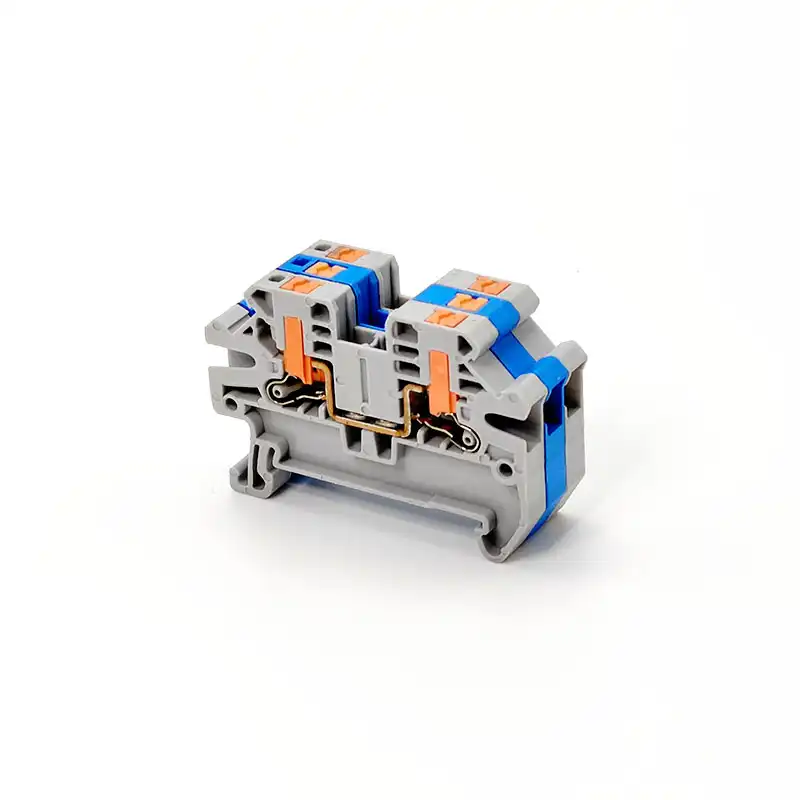
Which specifications matter most?
Check these seven as one system: rated voltage, rated current, conductor compatibility, physical format, connection method, environmental limits, and model-specific approvals. A part is suitable only when every field matches the application and the same standards column is used throughout.
Voltage
AC/DC, impulse, pollution degree and altitude.
Current
Conductor, temperature rise and derating basis.
Conductors
Solid, stranded, ferruled, quantity and strip length.
Geometry
Pitch, width, poles, levels, rail and accessories.
Connection
Screw torque or spring/push-in actuation details.
Environment
Temperature, material, flammability and exposure.
Approvals
Exact standard, file, conditions and fault rating.
Terminal block specification checklist at a glance
A useful specification is not “600 V, 30 A, 12 AWG.” It records the conditions behind every value and confirms that the block, conductor, accessories and finished assembly are compatible.
| Check | Record from the exact datasheet | Decision question | Common red flag |
|---|---|---|---|
| 1. Voltage | Rated voltage, AC/DC, impulse voltage, pollution degree, overvoltage category | Does the published rating apply to this circuit and installation environment? | Mixing an IEC value with a UL current or approval column |
| 2. Current | Nominal current, test conductor, ambient/test basis, derating or load curve | Can the complete conductor-terminal-enclosure system carry the load? | Treating “maximum load current” as a universal operating value |
| 3. Conductors | Solid/flexible/ferruled ranges, conductor count, strip length, material | Is the actual conductor preparation explicitly permitted? | Assuming one AWG/mm² range covers every conductor class |
| 4. Geometry | Width or pitch, poles, levels, dimensions, mounting, mating and accessories | Does the complete terminal strip fit and assemble correctly? | Confusing terminal pitch with creepage distance |
| 5. Connection | Technology, torque/tool or actuation method, strip length, insertion rules | Can production make the connection repeatably? | Using a generic torque chart instead of the exact product value |
| 6. Environment | Operating limits, material, UL 94 class, vibration, humidity, UV/chemical data | Do the documented conditions cover the real micro-environment? | Assigning the enclosure’s IP or NEMA Type to an open terminal block |
| 7. Approvals | Standard, mark, file/certificate, use group, SCCR conditions, exact part number | Will the part be accepted in the destination equipment and market? | Accepting a family brochure logo as proof for every model |
If a datasheet presents IEC, UL, CSA or hazardous-location data in separate columns, keep voltage, current, conductor range and conditions within the applicable column. The highest number on the page is not automatically the usable number.
Rated voltage is an insulation-coordination decision
Select the terminal block against the actual working voltage and the rating system that governs the equipment. Then confirm the insulation conditions that support that rating.
A terminal block’s voltage capability depends on more than the molded housing. Clearance through air, creepage along an insulating surface, material group, pollution degree, overvoltage category and—where relevant—installation altitude all affect insulation coordination. IEC 60664-1 provides the framework for low-voltage equipment; the terminal block product standard and the manufacturer’s approval data turn that framework into model-specific values.
Rated or nominal voltage
Match the published AC or DC value to the applicable standard column. Do not infer a DC rating from an AC marking, or the reverse.
Rated impulse voltage
Check the impulse value and overvoltage category when the installation can experience switching or supply transients.
Pollution and altitude
Use the micro-environment around the insulation. Condensation, conductive dust and higher altitude can change the required spacing.
Do not turn a design margin into a universal rule
A blanket multiplier such as “choose 1.25× system voltage” is not a substitute for the relevant code, insulation-coordination study or manufacturer data. First meet the exact circuit and approval requirements; then apply any project margin required by the system designer. For a deeper explanation, see SENTOP’s terminal block voltage rating guide.
Current rating belongs to a test configuration
The published current is meaningful only with its conductor cross-section, standard, temperature-rise limit and test conditions. The installed conductor and enclosure still need their own thermal checks.
Contact resistance produces heat in the clamping point and current bar. Adjacent loaded terminals, a warm enclosure, bridges, smaller conductors and limited air movement may change the allowable load. Use a manufacturer’s load or derating data when provided; do not invent a fixed “80% rule” or a universal percentage for every 15°C rise.
One model can legitimately publish several values
The following manufacturer data for Phoenix Contact UT 2,5 part 3044076 illustrates why the rating basis must stay attached to the number. It is an example of datasheet reading—not a recommendation for a SENTOP or third-party substitute.
| Published field | Value for the example part | What it demonstrates |
|---|---|---|
| IEC nominal data | 1000 V, 24 A, 2.5 mm² nominal cross-section | Voltage, current and conductor basis form one data set. |
| Maximum load current | 32 A with a 4 mm² conductor | The maximum is conditional on a different conductor size. |
| UL approval data | 600 V, 20 A, 26–12 AWG for listed use groups | The same hardware has different approval values. |
| Temperature-rise test | Requirement shown as rise ≤45 K; test passed | A test result supports the product rating but is not an enclosure temperature prediction. |
Determine the circuit load and applicable code → verify conductor ampacity → select a terminal model with compatible rated data → apply the model’s documented temperature/load conditions → evaluate the complete terminal strip inside the enclosure.
Wire range must match the actual conductor preparation
“0.2–4 mm²” is incomplete unless the datasheet says whether it applies to solid, stranded, fine-stranded, ferruled or multiple conductors.
Record the conductor material and class, minimum and maximum size, ferrule style, number of conductors per clamping point and exact strip length. AWG and mm² are different sizing systems; a datasheet may approve both without claiming they are exact equivalents.
- Separate every range. Solid, flexible and ferruled conductors may have different upper or lower limits.
- Check ferrule details. A plastic collar, TWIN ferrule or long sleeve changes the termination geometry.
- Verify conductor count. Two wires are permitted only when the exact clamping point and preparation are documented for two conductors.
- Use the stated strip length. Too short can reduce contact; too long can expose live copper outside the housing.
- Confirm copper versus aluminum. Never assume an aluminum conductor is allowed because it physically enters the clamp.
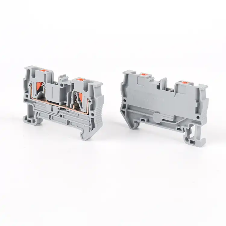
“Two clamping points; 0.5–2.5 mm² flexible copper with insulated ferrules; 0.5–4 mm² solid copper; one conductor per point; strip length to be confirmed from the approved model.” This is more actionable than “accepts 12 AWG.”
Geometry determines whether the whole terminal system fits
Electrical ratings do not reveal cabinet footprint, PCB compatibility or whether the selected jumpers, markers and end plates belong to the same system.
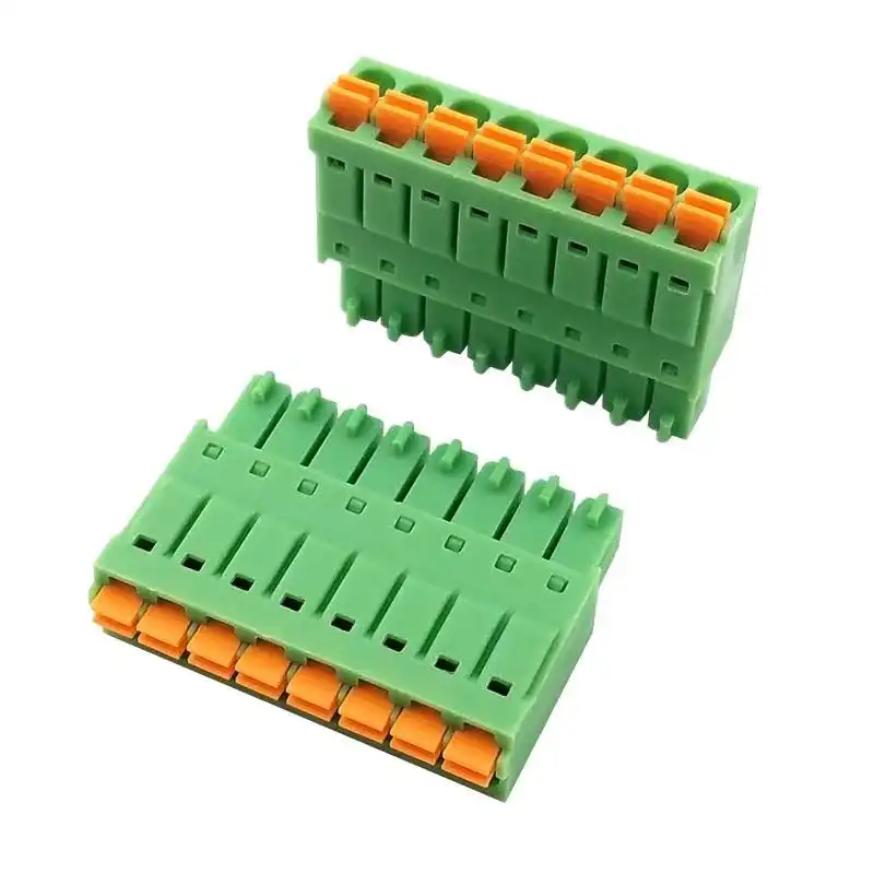
Capture more than pitch
- DIN rail: rail profile, terminal width, height above rail, depth, number of levels and required end brackets.
- PCB/pluggable: centerline pitch, pole count, pin layout, header angle, plug/header pair, keying and PCB footprint.
- Barrier/fixed: mounting-hole pattern, pole pitch, cover, screw/stud dimensions and required clearances around wiring.
- Every format: end plates, partitions, jumpers, markers, test plugs, disconnect/fuse accessories and spare-pole strategy.
Pitch is normally the center-to-center spacing between adjacent poles or contacts. Creepage follows an insulating surface; clearance is the shortest air path. Never use pitch alone to approve a voltage rating.
Connection technology defines the assembly process
Screw, spring-cage, push-in and plug-in designs can all be reliable when used within their published conductor and installation limits. Choose by production method, service access and mechanical environment—not by a generic claim that one type is always superior.
| Technology | Specify | Production control | Watch carefully |
|---|---|---|---|
| Screw clamp | Exact torque range, driver/blade, conductor preparation and strip length | Use a suitable controlled tool and the current work instruction | Under- or over-torque; unsupported retightening rules |
| Spring-cage | Opening/actuation method, conductor class, ferrule options and strip length | Confirm full insertion and use the specified operating tool | Inserting unsupported bare fine-stranded wire |
| Push-in | Direct-insertion conductor types, release method and test point | Prepare the conductor consistently and verify seating | Assuming every stranded conductor inserts without actuation |
| Plug-in / PCB | Mating pair, keying, pitch, orientation, retention and connection cycles | Control header/plug pairing and PCB footprint revision | Mating look-alike series from different families |
There is no universal torque-by-wire-size chart
Torque depends on the exact screw, clamp, current bar, housing and approval. Use the value on the product, datasheet or installation instruction for that part number. Do not automatically retighten after a fixed interval unless the manufacturer or maintenance program calls for it; some terminal designs are explicitly described as maintenance-free.
For screw-terminal work instructions, record the torque range in N·m and, where needed, lb-in; the allowed driver; tool calibration control; strip length; conductor/ferrule; and inspection method. SENTOP’s terminal block torque guide expands this process.
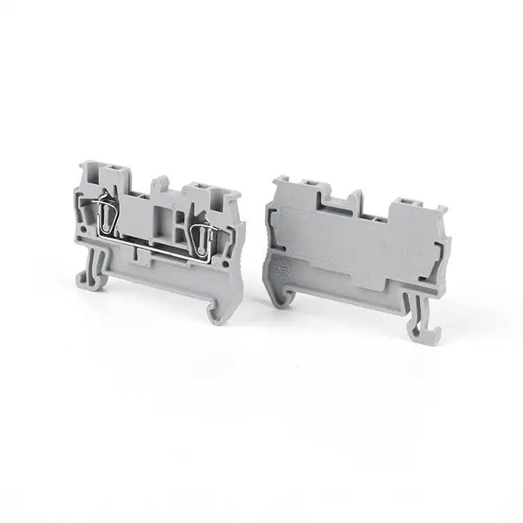
Material data must match the real micro-environment
The polymer name alone does not prove temperature, flame, UV, chemical or railway performance. Approve the exact material grade and product test data.
Operating limits
Check the product’s operating range, including self-heating notes. A polymer RTI or raw-material value is not automatically the terminal block’s usable temperature.
Flammability class
UL 94 classifications describe small-scale plastic test behavior at stated conditions. V-0 does not mean the complete terminal block is fireproof.
Pollution degree
Determine the micro-environment around the insulation, including expected condensation or conductive contamination—not only the room label.
Keep enclosure ratings in the right place
IEC 60529 classifies degrees of protection provided by enclosures, while NEMA 250 covers enclosure Types and their environmental conditions. An open DIN-rail block inside an IP54 or NEMA Type 12 cabinet does not independently become IP54 or Type 12. For exposed connectors, use the product’s explicit mated/unmated ingress data and installation requirements.
- Record minimum/maximum ambient, internal enclosure temperature and terminal self-heating basis.
- Confirm material grade, color, flammability data and any halogen, smoke or railway requirements.
- State humidity, condensation, dust, salt, oil, chemicals, UV, vibration and shock where relevant.
- For hazardous locations, require the exact Ex/UL hazardous-location approval and approved accessories—not a general industrial rating.
- For higher altitude, review clearance and product guidance rather than assuming sea-level spacing remains valid.
Approve the exact model, standard and conditions of use
A logo in a catalog is only a starting point. The part number, certificate or file, rating table, use group and accessories must support the intended equipment.
| Reference | Use it for | Do not infer |
|---|---|---|
| IEC 60947-7-1:2025 | Industrial support-mounted terminal and test-disconnect blocks for copper conductors within its scope | That every terminal product or every SENTOP model is certified to it |
| IEC 60947-7-2 | Protective-conductor terminal blocks with PE/PEN functions within scope | That a green/yellow housing alone proves protective-conductor performance |
| IEC 60947-7-3 | Fuse terminal blocks and compatibility with the specified standardized fuse-link | That an ordinary feed-through block can perform the fuse function |
| IEC 60947-7-4 | PCB terminal blocks fixed to printed circuit boards within its scope | That a rail-mounted block and a PCB terminal share the same installation conditions |
| UL 1059 | Assemblies of wiring terminals and supporting blocks within its scope | Suitability for every end product; UL’s scope expressly requires application evaluation |
| UL 94 | Controlled small-scale flammability classification of polymeric materials | A fire-resistance rating for the finished panel or installation |
| IEC 60529 / NEMA 250 | Protection provided by enclosures under their respective systems | An ingress rating for a bare, open terminal block |
Short-circuit ratings need the complete condition
If SCCR, short-time withstand current or fuse coordination matters, record the available fault current, voltage, upstream protective device, conductor and any required jumper or accessory. A kA value cannot be separated from the conditions under which it was evaluated. IEC short-time withstand current and UL SCCR are different metrics and must not be relabeled as one another. In a North American industrial control panel, verify how the terminal block is used in the equipment’s overall SCCR determination.
Also keep product categories separate: UL 1059 covers terminal blocks within its scope, while field-installed power distribution blocks are evaluated under a different product category such as UL 1953. Similar appearance does not make the products interchangeable.
Request the certificate or UL file for the exact manufacturer and part number, the applicable rating table and use group, declaration documents where required, and confirmation that the selected jumpers, end plates, fuse carriers or test accessories are covered. Certification availability depends on the exact SENTOP model and datasheet.
Turn seven checks into one clean RFQ
SENTOP can compare a customer model, drawing or BOM against electrical, conductor, mounting, accessory and market requirements. More complete input produces faster model matching and fewer sample revisions.
Feed-through, PE, disconnect, fuse or distribution; AC/DC; working voltage, current and fault requirement.
Minimum/maximum AWG or mm², copper/aluminum, solid/flexible/fine-stranded, ferrule and conductors per point.
DIN rail, PCB, barrier or panel mount; pitch, poles, levels, dimensions, orientation and available space.
Screw, spring, push-in or plug-in; preferred tool, torque control, strip length and assembly volume.
Temperature, humidity, condensation, dust, chemicals, vibration, altitude and hazardous-location needs.
Destination, standards/approvals, certificates, quantity, samples, annual demand, marking and OEM packaging.
End plates, end brackets, jumpers, markers, partitions, test plugs, fuse carriers, keys and mating headers.
Manufacturer/model, customer item code, product photo, drawing, datasheet or complete mixed BOM.
Start with the mounting and connection system
Use these SENTOP product families to narrow the mechanical format, then confirm every model-specific rating and approval.
DIN Rail Terminal Blocks
Feed-through, PE, disconnect, fuse and multi-level functions with rail accessories.
Explore DIN rail options → Controlled screw assemblyScrew Terminal Blocks
Specify torque, conductor preparation, strip length, mounting and exact rated data.
Explore screw options → Spring connectionSpring Terminal Blocks
Match actuation, direct-insertion capability, conductor class and environmental tests.
Explore spring options → Pluggable and PCBPlug-in Terminal Blocks
Control pitch, poles, orientation, keying, mating pair, PCB footprint and rated data.
Explore plug-in options →Related SENTOP engineering resources
Keep this page as the procurement checklist and use the focused guides for deeper datasheet work.
Terminal block specifications FAQ
Short answers to the most common datasheet and procurement mistakes.
Can I use a terminal block’s current rating at any ambient temperature?
No. Use the current rating only with its stated standard, conductor and test conditions. Check the manufacturer’s temperature/load data, adjacent loading, bridges, conductor ampacity and enclosure thermal conditions for the installed system.
Are AWG and mm² terminal block ranges directly interchangeable?
No. AWG and mm² are different sizing systems. A manufacturer may approve both ranges for one clamping point, but that does not make the displayed values exact equivalents. Follow the model’s approved conductor table.
How much torque should I apply to a screw terminal block?
Apply only the torque range specified for the exact part number in its marking, datasheet or installation instructions, using a suitable controlled tool. Wire size alone cannot determine a universal torque value.
Can I put two conductors in one terminal clamping point?
Only when the manufacturer explicitly approves that clamping point for two conductors of the stated sizes, types and preparation. Otherwise use separate clamping points, a documented TWIN ferrule solution or an approved jumper/distribution arrangement.
Does UL 94 V-0 mean a terminal block is fireproof?
No. UL 94 V-0 is a small-scale flammability classification for a polymeric material under specified test conditions. It is not a fire-resistance rating for the complete terminal block, panel or installation.
Standards and manufacturer data used
Use the latest edition required by your contract, market and equipment standard. Product data can change by revision and region.
- IEC 60947-7-1:2025 — scope and requirements for industrial terminal blocks and test-disconnect terminal blocks for copper conductors.
- IEC 60947-7-2 — protective-conductor terminal blocks with PE/PEN functions within scope.
- IEC 60947-7-3 — safety requirements for fuse terminal blocks and standardized fuse-link compatibility.
- IEC 60947-7-4 — requirements for PCB terminal blocks and current-temperature derating context.
- IEC 60664-1 — low-voltage insulation coordination, including clearance, creepage and altitude guidance.
- UL 1059, Edition 6 — terminal block scope and the need to evaluate suitability in the final application.
- UL 1953 — a separate scope for power distribution blocks; it does not replace UL 1059 terminal-block evaluation.
- UL Solutions: UL 94 tests — meaning and limitations of polymeric-material flammability classifications.
- IEC 60529 — degrees of protection provided by enclosures under the IP Code.
- NEMA Enclosures — NEMA 250 scope and enclosure Type context.
- Phoenix Contact UT 2,5 data — model-specific IEC/UL ratings, conductor ranges, torque, strip length and dimensions used as the datasheet example.
- OSHA 29 CFR 1910.333 — de-energization, lockout/tagging and verification requirements for covered electrical work in the United States.
Safety: terminal selection and installation should be performed by qualified personnel under the applicable electrical rules. Before service, de-energize, isolate hazardous energy, apply the required lockout/tagout procedure and verify the de-energized condition. This guide does not replace the approved product instructions or the responsible engineer’s design review.
