
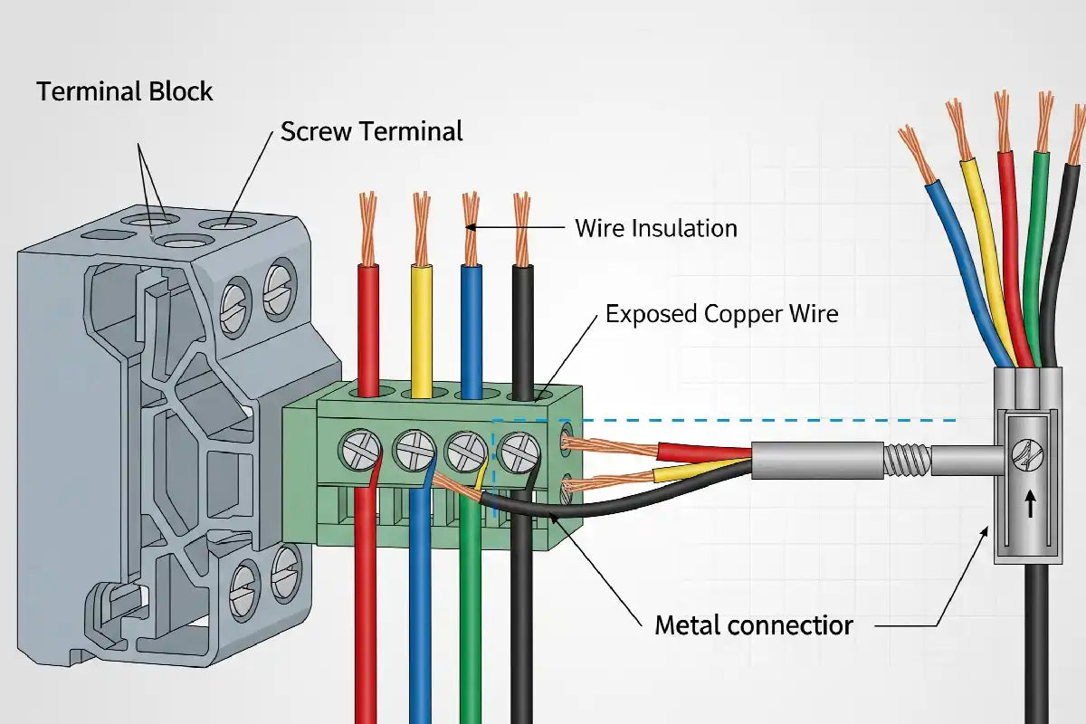
Can You Put Two Wires in One Terminal Block? When It Is Allowed
Sometimes—but only when the exact clamping unit is marked or documented for the intended two-conductor combination. If the data lists one conductor, or says nothing about multiple conductors, treat that clamp as one-conductor only.
The rule is about one clamping unit
“Two wires in one terminal block” can describe several different arrangements. Only one of them actually puts two conductors under one clamp.
Two conductors in one clamp
Use this only when the exact connection point documents the conductor count, materials, sizes, construction and termination process.
Both wires physically fit
A large opening, spare space or successful insertion does not prove contact pressure, retention, temperature rise or certification suitability.
One conductor per rated clamp
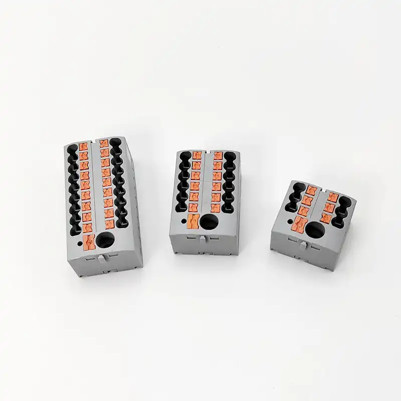
Use separate internally commoned ports, a distribution block or an approved jumper system when documentation does not permit a shared clamp.
Do not multiply ratings. Permission for two conductors does not double the terminal current rating. Never add the two wire ampacities or assume the clamp, jumper and common current path carry twice their marked current.
A terminal block can have several poles, levels, wire entries or an internal commoning path. None of those features proves that one opening accepts two conductors. The decisive evidence is the exact part number and exact clamping unit in the current marking, catalog data, instructions or certification record.
That evidence must match the installed combination: conductor material, solid or stranded construction, cross-section or AWG, equal- or mixed-size rules, ferrule arrangement, strip length, and the stated torque or spring-termination process. A nearby terminal from the same family may have different limits.
Words that look similar can mean different hardware
Use precise terms in drawings and RFQs so purchasing, production and inspection evaluate the same connection.
| Term | What it means here | What it does not prove |
|---|---|---|
| Clamping unit | One mechanical contact that secures a conductor or documented conductor combination. | That another opening on the product has the same allowance. |
| Connection point / port | A defined place where a conductor enters a clamp. | That several visible ports share one clamp or are internally common. |
| Two-wire terminal | Often a terminal with two separate connection points on one potential. | That two bare conductors may be stacked under one screw or spring. |
| Multi-conductor terminal | A product designed with several defined conductor entries. | That every entry accepts multiple conductors. |
| Twin ferrule | A ferrule barrel that combines two prepared stranded conductors. | That the receiving terminal permits that ferrule or those wire sizes. |
| Jumper / cross-connection | An approved accessory that electrically commons separate terminal positions. | That its current, temperature or fault-duty rating equals the terminal’s. |
A feed-through terminal also does not automatically provide isolation. Only a product specifically identified and documented as a disconnect or test-disconnect terminal provides that function. Separate clamps may improve traceability and test access, but they are not an energy-isolating means.
Four legitimate ways to bring two wires to one potential
The electrical destination may be common even when the conductors use separate mechanical clamps.
One rated clamp, two conductors
Use only the exact documented pair. Match count, material, construction, size and termination details.
Evidence requiredApproved twin ferrule
Both wires, ferrule, crimp tooling and receiving terminal must form one documented combination.
Model-specificSeparate commoned clamps
Each conductor gets a dedicated contact while the terminal provides an internal common electrical path.
Easy to inspectDistribution or jumper system
A rated block or approved cross-connection creates the branch without modifying a one-wire device terminal.
Clear branchingGive each branch its own rated port
When the real requirement is supply distribution, a purpose-built block is often more legible than crowding a device terminal. The incoming conductor, outgoing branches and any common bus remain visible in the drawing and accessible for inspection.
Separate ports still need exact validation. Confirm part number, conductor range, current path, voltage, temperature limits, mounting, required accessories and short-circuit conditions. Multiple holes are not proof that all holes are common or that any hole accepts two wires.
See SENTOP’s DIN-rail terminal block range and use the terminal block selection guide to turn the connection need into a model-level specification.
Documented permission—or choose a different design
Do not start by asking whether the conductors can be inserted. Start by asking whether the connection is documented.
Is the exact clamp identified for more than one conductor?
If no or unknown, stop. Use separate rated connection points.
Does the installed pair match every data row?
Check material, size, strand class, ferrule and equal-size restrictions.
Is the complete current path and end use acceptable?
Verify process, ratings, accessories, certification and installation rules.
No data is not a “maybe.” Silence does not authorize a shared clamping unit. Ask the manufacturer for exact written evidence or redesign the connection with a multi-conductor terminal, distribution block or approved jumper system.
Why “it fits” is not an engineering test
Two wires can enter an opening while receiving unequal contact pressure. One may move as a screw is tightened, strands may escape the contact zone, or insulation may enter the clamp. A spring designed around one conductor can also fail to control two separate conductor surfaces.
A marginal connection can raise resistance. Under load, that resistance creates localized heat, and thermal cycling can worsen the joint. Incorrect torque can leave a screw connection loose or damage the conductor and terminal. The correct value belongs to the exact product—not to a generic terminal type.
Appearance also says nothing about conductor-material compatibility, field-wiring approval, temperature rise, enclosure conditions or fault duty. A connection is acceptable only when the documented configuration and the complete equipment requirements agree.
Photo boundary: the example shows heat damage associated with an old aluminum-to-copper screw-terminal connection. It does not prove that two wires under one clamp caused the failure.

Eight data-sheet checks before you approve a shared clamp
Copy values from the exact part-number document and revision used in the build package. Do not borrow them from a family brochure.
- Exact part and clamping point. Record the technology, level, pole and port—not just the series name.
- Conductor count. Find explicit “two conductors,” “2 ×” or a two-conductor table for that clamp.
- Conductor material. Confirm copper, aluminum or any permitted intermixing. Physical fit and oxide inhibitor do not create approval.
- Size and construction. Match AWG or mm², solid, stranded or fine-stranded entries and any equal-size requirement.
- Ferrule arrangement. Confirm single/twin barrel, collar, wire range, strip length, crimp tool and receiving-terminal allowance.
- Termination process. Use the exact screw torque/tool or spring/push-in preparation, actuator and insertion method.
- Electrical path. Verify current, voltage, temperature/derating, jumper or bus rating, and applicable short-circuit conditions.
- End-use status. Check field-wiring suitability, certification/Conditions of Acceptability, enclosure and local installation rules.
Individual ranges cannot be combined. If a terminal accepts one 4 mm² conductor and one 2.5 mm² conductor separately, that does not prove it accepts the two together. The pair needs its own documented allowance.
For a deeper explanation of voltage, current, conductor range, torque, pitch and approval data, use SENTOP’s terminal block specification guide. For the complete preparation and commissioning workflow, keep this decision separate from the terminal block wiring guide.
A twin ferrule is not a universal workaround
A twin ferrule organizes two stranded conductors into one crimped barrel. That shape can be useful in control wiring, but it does not turn an undocumented one-conductor terminal into a two-conductor terminal.
The two conductors, ferrule, crimp tool and receiving terminal must form one documented combination. Match conductor material, equal-size requirements, strand class, barrel and collar geometry, strip length, crimp profile, and the terminal’s connection table.
UL 486F covers ferrules for two stranded copper conductors of the same size within its scope. Ferrule certification alone still does not approve every receiving terminal. The terminal and ferrule instructions must both permit the installed configuration.
Never rely on “it now counts as one wire.” The ferrule changes the termination geometry, but it does not bypass conductor-count, current, temperature or certification limits.

Why there is no universal yes or no
One product documents precise two-conductor combinations. Another current product family requires one conductor per clamping unit.
Phoenix Contact GSMKDS 3/2, 1733020
The current product data lists these exact examples:
- Two same-size rigid conductors: 0.2–1.5 mm²
- Two same-size flexible conductors: 0.2–1.5 mm²
- Two flexible conductors with ferrules without collars: 0.25–0.75 mm²
- Two same-size flexible conductors with a TWIN ferrule and collar: 0.5–1.5 mm²
- Strip length: 8 mm; tightening torque: 0.5–0.6 N·m
Boundary: these values belong only to part 1733020. Its market approval ratings differ, and the ranges do not transfer to a DIN-rail block, breaker lug or visually similar screw terminal.
View the current product dataWAGO I/O System 750/753
WAGO’s current conductor-termination instructions state that only one conductor may be connected to each clamping unit.
This is a product-family instruction, not a ban on every spring terminal. Other spring products may offer several independent clamping units or an expressly documented twin-ferrule range.
The comparison proves the governing principle: connection technology alone does not decide conductor count. The exact product documentation does.
Read the current WAGO instructionsTesting is context-specific. WAGO also discusses one conductor per clamping unit for insulation-resistance testing in specified DIN VDE 0100-718/-482 building applications. That is not a universal rule for every jurisdiction, terminal or circuit; it shows why actual installation test requirements belong in the selection review.
Screw, spring and push-in do not give automatic answers
Each technology has product-specific process controls. Never transfer a practice or value from another terminal family.
Torque is exact-part data
Some screw terminals are evaluated for two conductors; others are not. Follow the specified conductor preparation, tool and torque range. Do not “tighten by feel.”
Explore screw terminal blocksOne clamp may still mean one wire
Check strip length, strand class, permitted ferrule, actuator and insertion instructions. A multi-conductor spring block commonly uses several independent clamps.
Explore spring terminal blocksBoard data does not transfer
A PCB terminal may document a two-wire range, but that permission does not apply to DIN-rail products, equipment terminals or field-installed wire connectors.
Review PCB terminal optionsA product rating is not a universal installation permit
Use the standard, certification record, complete equipment marking and locally adopted installation rules for the destination market.
United States
NEC 110.14 requires a terminal intended for more than one conductor to be identified for that use. UL 1059 covers terminal blocks within its scope; UL 486A-486B covers applicable wire connectors; UL 486F covers ferrules.
Local adoption governs the enforceable NEC edition. A UL Recognized component still has Conditions of Acceptability and end-product limits.
Canada
Use CSA C22.1 as adopted by the province or territory and equipment approved for its intended purpose. CSA C22.2 No. 158:23 covers terminal blocks within its scope.
A U.S.-only mark or rating is not automatically Canadian approval. Verify the exact model, certification record and installed conditions.
IEC markets
IEC 60947-7-1:2025 covers specified industrial terminal blocks with screw-type or screwless clamping units for copper conductors. The standard scope is not a product rating or an aluminum-conductor approval.
Local wiring rules, the manufacturer’s declared conductor combinations and market-specific conformity still govern.
For a market-by-market overview, see the upgraded terminal block certification guide. For a deeper component-standard review, use the UL 1059 requirements guide.
Do not carry “sometimes yes” into every device terminal
A terminal block, breaker lug, panelboard neutral, PCB connector and building-wire connector are different evaluated products.
Panelboards and breaker terminals
UL panelboard guidance requires an individual terminal for each branch-circuit neutral conductor. Circuit-breaker terminals ordinarily accept one conductor per hole unless the breaker is specifically marked for the permitted multiple-conductor connection.
Follow the complete equipment marking, including the panel label and breaker compatibility—not only the marking on a removable lug.
Field wiring and factory wiring
A UL Recognized terminal block is a component for use within evaluated end equipment. Recognition is not the same as a Listed standalone field-installation product.
Check the use group, field-wiring suitability, conductor range, spacing, temperature and Conditions of Acceptability. In a UL 508A panel, a field connection terminal must be identified as suitable for that purpose.
The two-conductor rating proves only the specified connection configuration. It does not approve the resulting splice, tap, branch circuit, conductor ampacity, overcurrent protection, enclosure fill, short-circuit rating or panel modification.
Follow the actual current path
A branch, pass-through and low-current common do not load a terminal in the same way.
Terminal rating
Keep the complete clamping point within its marked current and temperature conditions. Two conductors do not double it.
Jumper or bus
An accessory may be the limiting component. Verify its current path, permitted terminal family and installed configuration.
Temperature
Account for enclosure ambient, grouping, conductor size and adjacent heat. Use exact derating data where provided.
Fault duty
Check the completed assembly’s protective-device and short-circuit requirements. A terminal rating alone does not set panel SCCR.
Verify the termination only in an electrically safe work condition
Opening an enclosure or changing a terminal connection is not a casual visual check.
Control every source
Identify line, backfeed, control and stored-energy sources. Apply the required lockout/tagout process and prevent re-energization.
Verify absence of voltage
A qualified person uses suitable test equipment on every exposed work point. A switch or breaker in OFF is not proof.
Compare with exact data
Check insertion, stray strands, trapped insulation, damage, discoloration and movement against the current product instructions.
Do not use indiscriminate periodic re-torquing or a live “tug test.” Follow the manufacturer’s maintenance process. Visual or thermal inspection cannot turn an undocumented two-wire termination into an approved one.
For the broader safety framework, see how to improve terminal block safety. For identification and documentation practices, use the terminal numbering and labeling guide.
Make the decision traceable
The goal is one approved configuration shared by engineering, purchasing, production, inspection and service.
State the electrical intent
Define pass-through, branch, common, device input or a documented test/disconnect function.
Identify the exact hardware
Record manufacturer, complete part number, level, pole, clamping point and every required accessory.
Attach the governing connection data
Reference the page and revision that explicitly permits the conductor count and combination.
Lock the conductor and process details
List material, size, strand class, ferrule/tool, strip length and torque or insertion method.
Review the complete current path
Confirm terminal, jumper, bus, enclosure temperature, overcurrent protection and fault-duty conditions.
Make it inspectable
Provide labels, wire markers, routing and access that let a technician trace each conductor and use documented test features.
Control substitutions and field changes
If a second wire is added to an undocumented clamp, treat it as a redesign. Update the BOM and drawing before work proceeds.
Replace “two-wire terminal” with verifiable inputs
Send the actual connection requirement so SENTOP can review the terminal architecture, model fit, accessories and documentation instead of guessing from a vague description.
- Conductor count per clamping unit
- Material, AWG/mm² and strand class
- Same or mixed sizes; ferrule requirement
- Voltage, current and current-path diagram
- Ambient, enclosure and fault-duty conditions
- Market standards, certification and quantity
Two wires, one terminal: clear answers
Is it ever okay to put two wires under one screw terminal?
Yes, but only when that exact screw-terminal clamping unit is marked or documented for two conductors and the installed conductor pair, preparation and torque match its instructions. A screw that is physically large enough is not evidence.
Does a two-wire terminal block mean two wires can share one clamp?
Not necessarily. It often means the block has two separate connection points on one electrical path. Check the internal diagram and conductor-count data for each clamping unit.
Can two different wire sizes share one terminal?
Only when the exact product documentation expressly permits that mixed-size combination. If the two-conductor row requires equal cross-sections, two different sizes are not allowed even when both appear in the one-wire range.
Can a twin ferrule make two wires acceptable in any terminal?
No. A twin ferrule does not override the terminal’s conductor-count limit. Both wires, the ferrule, crimp tooling and the receiving terminal must form a documented combination.
Do screw terminals always accept two conductors?
No. Some screw terminals are evaluated for defined two-conductor combinations and others are not. Connection technology never replaces exact product data.
Do spring terminals always allow only one conductor?
No. Some spring products allow one conductor per clamping unit, while purpose-built multi-conductor products provide several independent clamps. A few products may document a twin-ferrule range. Follow the exact model instructions.
What should I use when a breaker or device terminal allows only one wire?
Use an appropriately rated external terminal block, distribution block or other approved distribution method, then run one permitted conductor to the device. Do not improvise a second conductor at the equipment terminal.
Does connecting two wires double the terminal current rating?
No. The complete terminal, clamp, jumper and common current path remain limited to their own ratings and applicable derating conditions. Conductor ampacities are not added to create a larger terminal rating.
Can copper and aluminum wires share a clamp if oxide inhibitor is used?
Only when the connector is identified for those materials, their intermixing and the conditions of use. Oxide inhibitor does not create approval; use it only when the connector instructions require or permit it.
What records should stay with the panel build?
Keep the exact terminal data sheet or manual revision, wiring diagram, approved conductor combination, ferrule and tool details, strip length, torque or process record, and ratings for jumpers or distribution accessories.
Sources used for the connection boundaries
- UL Solutions — Deadfront Switchboard Replacement Guide: conductor-count marking and torque principles.
- UL Solutions — Panelboards Guide: panelboard terminal and branch-neutral boundaries.
- UL Solutions — Circuit Breaker Guide: multiple-conductor breaker-terminal marking.
- UL 1059, Edition 6: current terminal-block component standard scope.
- UL 486F, Edition 3: wire ferrule requirements within its scope.
- IEC 60947-7-1:2025: current IEC terminal-block product standard scope.
- Phoenix Contact — GSMKDS 3/2, 1733020: exact two-conductor example.
- WAGO — I/O System 750/753 conductor termination: current one-conductor-per-clamp example.
- WAGO — Rail-mount terminal application tips: specified insulation-test context and alternatives.
- Weidmüller — Feed-through terminal blocks: 2-, 3-, 4-wire and multiwire architectures.
- OSHA 1910.333: de-energization and qualified-person safety boundary for workplaces.
- NFPA 70 (NEC), 2026: current national model code; local adoption governs enforcement.
