
Repeat one approved identifier
The terminal marker, drawing, strip plan, and exported label data use the same controlled ID—or a documented cross-reference when identical text is not practical.
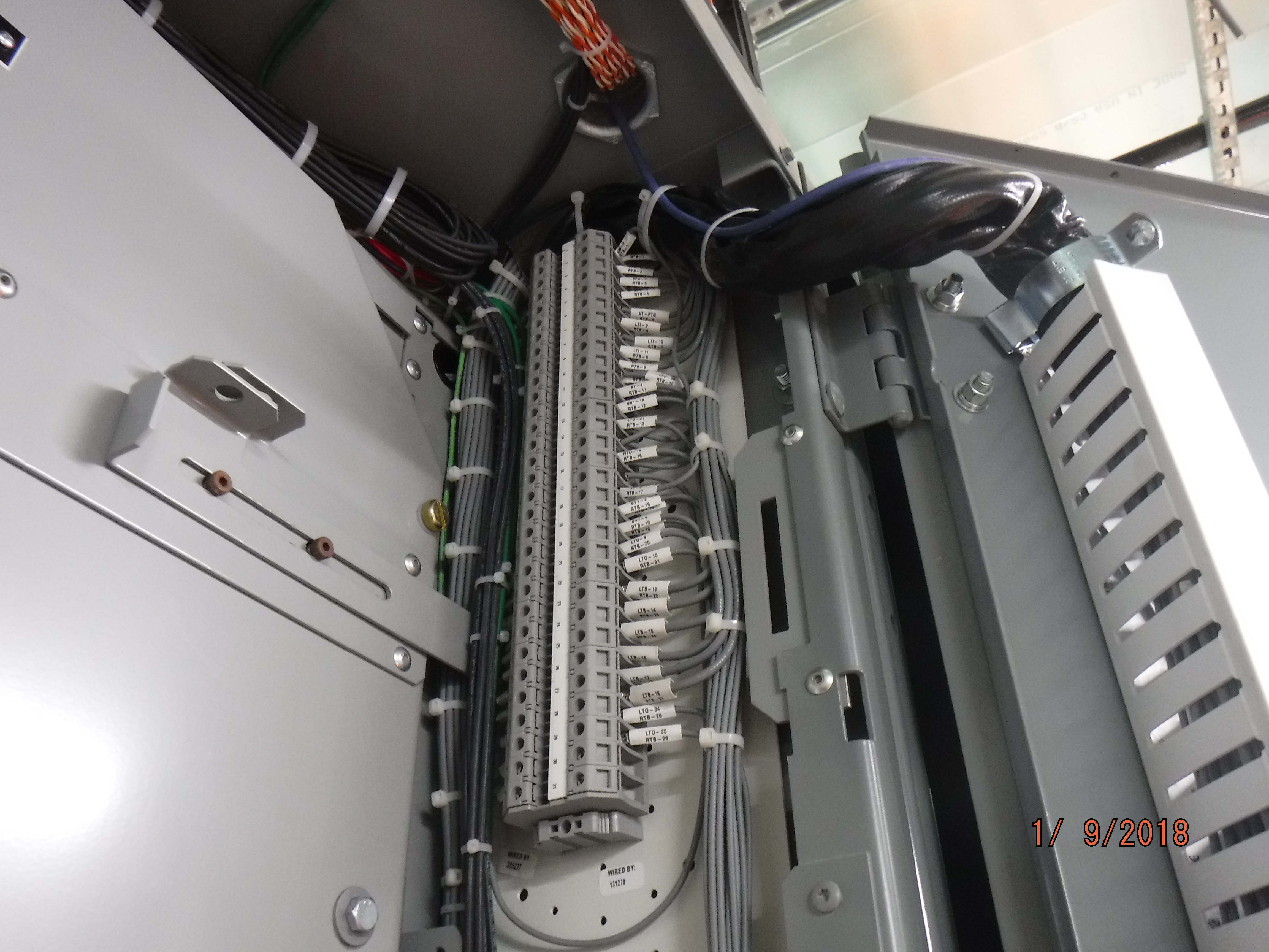
A reliable terminal label is a data key, not just a printed number. It should identify one physical terminal point, lead the reader to the same object in the current drawing and terminal plan, remain readable in the real environment, and stay controlled when the panel changes. Use the seven practices below to build that complete system.

The marker on the terminal should point to one clear object in a controlled information system. A technician must be able to move from the physical terminal to the latest drawing, terminal-strip plan, conductor record, and approved change history without guessing.
There is no universal rule that every project must use simple sequence numbers, wire numbers, or function codes. Choose a designation grammar that fits the governing equipment standard and the project. Then apply it without hidden exceptions.
Make every terminal point unambiguous, traceable, readable, compatible with its marker system, and controlled through the current as-built revision.
The terminal marker, drawing, strip plan, and exported label data use the same controlled ID—or a documented cross-reference when identical text is not practical.
Rail position and color can support recognition, but text or another unambiguous identifier must remain the primary route to the documentation.
Many labeling problems start when one short code is forced to describe several objects. Keep the physical point, connected conductor, circuit or potential, and document reference in separate fields—even if the printed marker shows only the most useful part.
Identify the strip or group, position, and level. This tells a person exactly where to find the connection.
A wire ID follows the conductor. It may appear at both ends and can connect two differently named terminal points.
Function and potential belong in the design data. Keep them traceable without assuming that one color or short code explains the whole circuit.
This example combines the panel, strip, terminal position, and level. Your approved scheme may use another order, separator, or reference-designation method. Define the grammar before production.
A label printer is only one stage. The stronger control is the path that starts in engineering data, sends the approved IDs to production, checks the physical panel, and returns every field change to the released documents.
State object types, scope, separators, level codes, reserved terms, and ownership.
Publish one controlled convention.Use the approved drawing or engineering database to produce terminal, wire, and label data.
Avoid manual retyping.Use a compatible marker carrier and qualified print system for the terminal family and environment.
Keep the strip order visible.Compare the physical terminal, marker, wire, bridge, accessory, and document record.
Resolve every mismatch.Approve changes, archive replaced files, and make the current revision available to service teams.
Close the information loop.Start with the naming rules and engineering data. Then address uniqueness, information layers, marker durability, readability, and revision control. Each practice below solves a different failure point.
Write down the object types, code order, separators, uniqueness scope, level notation, spare-terminal treatment, and approved abbreviations. A scheme can use sequential positions, project reference designations, circuit-related codes, or a combination. The key is that the rule is documented and applied the same way by engineering, production, commissioning, and service.
Use the released electrical design or controlled engineering database to produce the terminal plan and label file. Import or export data through a checked interface when possible. Manual retyping creates a second uncontrolled list. The drawing, terminal-strip plan, wire schedule, BOM, and printed marker should come from the same approved dataset or a managed cross-reference. Manufacturer engineering software provides one practical example of this connected workflow.[12]
A short number such as 12 may repeat on several strips. The complete ID must still resolve to one point. Multi-level blocks need a defined level field. Multiple rails or panels need enough context to prevent a duplicate. Check uniqueness in data before labels are printed, then check the physical strip after assembly.
The terminal-point ID locates the connection. The wire or cable-core ID follows the conductor. The circuit or potential describes the electrical meaning. These fields can be shown together in a terminal plan, but one should not silently replace another. This is especially important when one wire joins two terminal points with different point IDs.
Choose the marker carrier that fits the exact terminal family. Then evaluate the marker material, ink or ribbon, printing or engraving process, attachment, and mounting surface as one system. Check the real exposure: temperature, UV, moisture, oil, cleaners, abrasion, vibration, and maintenance handling. A material name or printer type alone does not prove durability.
Use clear characters, stable orientation, enough spacing, and strong contrast. Validate the finished marker at the actual access distance and lighting, with nearby wires and covers in place. There is no universal font size for every terminal. Color can speed recognition, but the text or symbol must still carry the identifier and the project must respect any reserved safety or conductor colors.[3]
Define who may create or change an ID. Update the engineering source first—or record the field change immediately under the approved process. Reprint the marker, update the drawing and terminal plan, verify the physical point, then release a new as-built revision. Archive replaced files so an older printout cannot quietly become the working reference.
The terminal manufacturer may mark ratings, wire data, model information, certification symbols, or molded connection positions. The panel builder adds circuit and terminal-point identification for the finished assembly. One does not replace the other.
Exact model, terminal points, ratings, conductor range, strip length or torque instructions where applicable, certification evidence, and manufacturing traceability belong to the product data and markings.
Panel, terminal strip, terminal point, level, wire, function, potential, drawing location, revision, and as-built status belong to the project information system.
A printed marker survives as a system. Check the carrier or marker groove, media, ink or ribbon, printing process, surface, preparation, attachment, and environmental exposure together. Use the exact product data instead of a universal material shortcut.
| Selection input | What to confirm | Useful evidence | Common bad shortcut |
|---|---|---|---|
| Terminal compatibility | Marker groove, pitch, carrier, visible area, cover clearance, and family accessories. | Exact marker and terminal order numbers, compatibility table, drawing, and sample fit. | Assuming a marker fits because the terminal width looks similar. |
| Temperature | Operating and storage range for media, print, adhesive if used, carrier, and mounting surface. | Supplier data for the complete media/print combination under the intended duty. | Applying one temperature limit to every polyester, ink, ribbon, or engraved part. |
| Oil and chemicals | Actual cleaners, oils, solvents, process fluids, contact time, and cleaning method. | Chemical-resistance data or a project test using the finished printed marker. | Calling a material “chemical resistant” without naming the chemical or exposure. |
| UV, moisture, and washdown | Enclosure protection, sunlight, condensation, water, pressure, detergent, and drying cycle. | Outdoor/weathering data, enclosure evidence, and a test that matches the application. | Assuming an outdoor enclosure makes every internal adhesive or print system suitable. |
| Abrasion and vibration | Retention in the marker groove, rubbing from conductors, handling, and machine vibration profile. | Retention data, abrasion result, installed sample, and post-wiring inspection. | Claiming every adhesive fails or every snap-on marker survives all vibration. |
| North American label evaluation | Whether the equipment standard calls for an evaluated permanent marking or label system. | UL 969 covers specific combinations of media, print system, surface, and use; application acceptance remains tied to the end-product requirements.[6] | Treating one “UL label” statement as approval for any printer, ribbon, surface, or environment. |
Sample before release: print the longest real identifier, install it on the selected terminal, complete the wiring, add covers and ducts, then inspect readability and retention under the actual access conditions. A blank marker sample does not test the finished print.
Terminal markers and conductor markers have different mounting points. A wire-label band, sleeve, or wrap must not overlap a ferrule, bare conductor, spring gate, clamp, insertion-depth area, or inspection window.


Verify the installed panel after wiring is complete. The review should compare physical objects with the released information set, not only check whether a marker exists.

The printed ID stays short. The controlled record behind it carries the information each team needs to design, build, inspect, purchase, and service the terminal strip.
Use the released terminal plan to assemble blocks, end parts, bridges, markers, covers, and accessories in a repeatable sequence. Verify the full point ID after wiring.
Solutions for panel builders →Connect the schematic, strip BOM, marker file, inspection focus, approved model, packing sequence, and change revision so purchasing and production use the same release.
Support for equipment manufacturers →Keep the terminal point, wire, PLC channel, sensor or actuator, cable core, and latest field change linked. Clear labels shorten the search path but do not replace safe electrical work.
Automation and machine control →No single standard gives one numbering format for every control panel. Use the standards that match the object, equipment, destination, certification program, and contract. Then document the project-specific syntax and verification method.
System identification, terminal and conductor identification, drawing rules, machine requirements, terminal-block product tests, and label-system durability are separate subjects. Do not turn one standard’s scope into a universal panel-labeling rule.
IEC 61666 gives general principles for identifying terminals within a system. IEC 81346-1 gives rules for structuring systems and creating unambiguous reference designations that link objects to information.[1][2]
IEC 61666 · IEC 81346-1The consolidated edition covers identification and marking of equipment terminals, conductor terminations, and certain conductor colors or alphanumeric notation. It is the better starting point for safety-related identification than an invented color palette.[3]
View the official IEC scopeIEC 61082-1 covers presentation rules for electrotechnical documents. IEC 60204-1 and NFPA 79 can add machine-specific wiring, marking, documentation, and verification requirements when the equipment falls within their scope. Use the edition required by the project or authority.[4][9][10]
IEC 60947-7-1 and UL 1059 address terminal-block products within their scopes; they do not create one plant-wide numbering format. UL 969 addresses specified label-system combinations and end-use conditions. Verify the exact component and application evidence.[6][7][8]
SENTOP supports component matching around your panel and project. Send the terminal models or strip drawing together with the numbering convention, marker text, environment, quantities, and document needs. The goal is to keep the block, marker, accessory, label sequence, and approved release connected to the order.
These answers cover the decisions that most often cause confusion during design reviews, panel inspection, and field changes.
There is no universal best format. Use a written system that makes every complete identifier unambiguous within the declared project scope. A practical identifier can combine the panel or location, terminal strip, position, and level. Define separators, abbreviations, spare treatment, and revision rules before creating drawings or print files.
Not necessarily. The terminal ID identifies a physical connection point, while the wire or core ID identifies a conductor. They may share a circuit reference, but they should remain separate controlled fields and be linked in the schematic, terminal plan, conductor list, or other approved project record.
Include a defined level code with the strip and position so each connection point remains unique. For example, a project might use X1:12-A and X1:12-B, but the letters and separators are only examples. Confirm the physical level order from the exact terminal drawing and document the project rule.
Give each installed spare a controlled identifier and record its status as SPARE in the terminal plan or database. Reserved number ranges or suffixes are acceptable when documented. Do not renumber commissioned terminals only to remove a gap, because that change can break links across drawings, cables, I/O records, and service documents.
Requirements depend on the equipment, conductor or terminal function, destination, and applicable standard. Use text or another unambiguous symbol as the primary identification. Color can support grouping, but it must not replace the identifier or conflict with colors reserved for specific conductors or terminals.
No single font size fits every marker and installation. Use the largest clear text that fits the approved marker without crowding. Check the longest real code after the panel is wired, considering lighting, viewing angle, covers, wire ducts, character spacing, and easily confused characters such as 0/O and 1/I.
They can be used when the exact label material, print system, attachment surface, temperature, chemicals, moisture, abrasion, and equipment requirements support the application. A snap-in marker made for the terminal family often simplifies fit and alignment, but neither adhesive nor snap-in construction is universally suitable.
Maintain one approved information source, generate drawings and marker files from it where practical, and validate field mapping, duplicate IDs, sequence, and printed output before release. After assembly, compare the installed strip with the approved data. Process every field change through the same revision and as-built approval workflow.
Share the strip drawing, circuit and conductor data, numbering convention, marker text, environment, market requirements, quantities, and delivery plan. SENTOP can help match the component set and documentation inputs for your engineering approval.
