
Solid conductor
One metal core. It is relatively stiff and often holds a neat fixed route. Many compatible push-in terminals allow direct insertion within a stated range.

Neither conductor type is always better. Match the actual conductor class, size, material and end preparation to the exact terminal data. Then check the connection method, circuit duty, motion, environment and controlled assembly process.
Solid wire is stiff and keeps a formed route. Stranded wire bends more easily. Those traits affect panel routing, cable service and insertion, but they do not prove that either wire fits a terminal.
The exact terminal instructions or an applicable certification path must support the real conductor construction, size and material. They must also support the bare, ferruled, compacted or multi-conductor condition. A conductor that fits is not necessarily one the terminal is identified to accept.
The terminal sees a geometry and prepared end. A nominal AWG or mm2 value does not describe that full interface. Use the AWG wire sizing guide for size context, then return to the exact conductor row.
One metal core. It is relatively stiff and often holds a neat fixed route. Many compatible push-in terminals allow direct insertion within a stated range.
Several wires form one conductor. It is more flexible than solid wire, but its exact strand build and cable standard still matter at the clamp.
Many small strands increase flexibility. IEC Class 6 is more flexible than Class 5. Neither class proves terminal or motion-cycle approval.
A crimped sleeve contains strands and creates a defined end. The ferrule size, length, collar, crimp and terminal entry must form an approved combination.
Some product data groups conductors by stiffness for a process. Do not translate rigid automatically to solid only. Read the product definitions.
IEC 60228:2023 defines conductor classes, dimensions and resistance for cable conductors. It does not certify a conductor-terminal combination. North American Class B, C, G, H, I, K and M terms use a different classification system, so do not convert classes from memory.
A solid core presents a stable shape. A loose strand bundle can spread or fray when handled outside the approved method. Fine strands often need the clamp opened with a tool, a lever, or a documented ferrule.
A lever or spring can make insertion easier. It does not make every conductor acceptable. This image shows a splicing connector, not a universal DIN-rail terminal example.
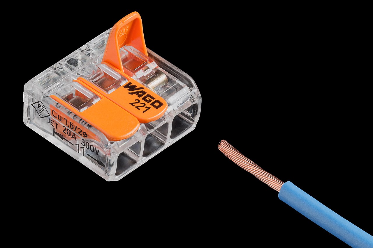
Use these differences to screen options. The product data still makes the final decision.
| Decision factor | Solid wire | Stranded or flexible wire | What to verify |
|---|---|---|---|
| Fixed routing | Holds a formed route well and can simplify short, static panel runs. | Routes around tight paths more easily and supports harness work. | Cabinet layout, bend radius, support, access and terminal data. |
| Motion | Repeated flexing near the terminal can fatigue a solid core. | More flexible does not mean continuous-flex rated. | Use a motion-rated cable, stated bend radius, cycle duty and strain relief. |
| Direct push-in | Often has a stated direct-push range because it is rigid. | Bare stranded wire may need a tool; fine-stranded wire may need a ferrule. | Read the direct-plug row, not only the overall connection range. |
| Repeated service | End shape is stable, but damage still requires replacement. | An approved ferrule can improve strand control during repeat insertion. | Service frequency, inspection rule and documented ferrule system. |
| Vibration | Do not assume a solid core is unsuitable from wire type alone. | Do not claim vibration life from strand count alone. | Cable support, terminal test data, motion at the clamp and enclosure duty. |
| Process cost | May reduce end-preparation steps in a compatible terminal. | May need ferrules, tools, inspection and more process control. | Total build, tooling, training, traceability and service cost. |
For repeated motion, use a cable that is rated for the real flex pattern and cycle duty. Keep bending away from the clamping point. Add the specified strain relief. A fine-stranded conductor alone is not a continuous-flex guarantee.
These examples show how to read the fields. They are not values for another terminal family.
The current product page separates rigid, flexible, ferruled and two-conductor entries. It also states the stripping length and tightening torque.
Lesson: torque and strip length belong to the exact part. Do not copy its 0.5 to 0.6 N m or 9 mm values to another product.
The product page lists overall rigid and flexible conductor ranges. It also gives separate directly pluggable entries, including a narrower ferruled range.
Lesson: accepted by the clamp and directly pushable are different claims.
Color, connection method, regional approval, accessories and even a nearby catalog number can change the entries. Save the current data sheet for the BOM part.
Use a ferrule only when the terminal instructions or an applicable certification path supports the full conductor-ferrule-terminal application.
A correctly selected ferrule gathers fine strands and creates a repeatable end. It can reduce fraying and support insertion into a compatible terminal.
It does not increase wire ampacity, expand the terminal range or turn an unlisted combination into an approved one. It also does not automatically permit direct push-in or two conductors in one clamp.
For the deeper decision, read when ferrules are required.

Start with the exact connection method. Then find the row for the actual conductor and end.
Verify the conductor row, strip length, torque and number of conductors. Use the marked value and controlled torque tool. More torque is not better.
Opening the clamp can allow conductor types that are not stiff enough for direct push-in. Use the stated operating tool and insertion method.
Check the direct-plug range separately. A terminal may accept flexible wire with a tool while direct insertion requires solid or ferruled wire.
A lever simplifies clamp operation for flexible wire. The permitted size, conductor type, strip length and end preparation remain model-specific.
Verify conductor material, strand class, lug, crimp tool, hardware and torque. The terminal is only one part of the connection system.
Assume one conductor per clamping unit unless the exact terminal lists two. Two ports are not the same as two wires under one clamp.
Check feed-in blocks, bridges, test points, partitions and end plates with the terminal. A bridge can have a lower current or conductor condition than the base terminal.
The terminal current field is not the conductor ampacity. It also does not replace the circuit protective-device or panel SCCR review. Use the guide to current rating versus actual load.

Under UL 508A, a 10 kA terminal-block value can be a default component value within the industrial-control-panel SCCR method. It is not an interrupting rating or a universal terminal capability. The completed assembly still must be checked against the available fault current.
A copper terminal scope does not transfer to aluminum. A terminal for more than one conductor or for aluminum must be identified for that purpose. Follow its conductor, preparation, compound and torque instructions.
Route, motion, heat, vibration and service access can matter more than a generic solid-versus-stranded preference.
This guide does not authorize installation or live work. Qualified persons must identify and isolate every source, apply the site's lockout/tagout procedure, control stored or backfed energy, verify that equipment cannot restart, and use suitable test equipment to verify exposed circuit parts are de-energized.
Each step must remain tied to the exact terminal and cable record. Start with the broader terminal-block selection checklist, then document this conductor interface.
State fixed run, field cable, moving lead, high-density control wire, higher-current circuit or another real use.
List material, AWG/mm2, conductor class, cable type, insulation, duty, motion and vibration conditions.
Use the full part number, connection technology, approval record and accessory system. A family name is not enough.
Check rigid, flexible, fine-stranded, ferruled, direct-push, compacted and one- or two-wire entries.
Use the exact strip length, torque, tool, lever or push method. Add a ferrule only when documented.
Review current, voltage, temperature, OCPD, SCCR, bridge, enclosure, strain relief and destination approval.
Issue the wire spec, terminal, ferrule, tools, drawings, inspection points and approved substitution rules.
Each shortcut removes one of the conditions that made the terminal data valid.
Discoloration can relate to the conductor, terminal, crimp, torque, load, environment or several factors at once. Preserve records and let qualified personnel inspect the complete path.
A thermal image or load reading is evidence from one state. It does not replace the design current, conductor data, terminal temperature conditions or controlled shutdown process.

"2.5 mm2 terminal" is not enough for a compatibility review or controlled substitution.
For release, use a terminal-block RFQ checklist and document the conductor and terminal in the BOM.
One clamping unit normally receives one conductor unless the terminal instructions or applicable certification explicitly permit two conductors, including the stated conductor sizes, construction and twin-ferrule condition where used. For more detail, see two conductors in one terminal.
Name the destination market and adopted edition. Compliance in one layer does not prove the complete connection.
| Reference | What it covers here | What it does not prove |
|---|---|---|
| IEC 60228:2023 | Conductor classes, dimensions and resistance for cable conductors | Compatibility with a particular terminal |
| IEC 60947-7-1:2025 | Industrial terminal blocks for copper conductors within its scope | Aluminum use or every specialized terminal function |
| IEC 60352-7:2026 | Spring-clamp connections within its defined scope | Permission to ignore the exact product instructions |
| UL 1059, Sixth Edition | Terminal-block product evaluation in its scope | Complete-panel suitability or any unlisted wire condition |
| UL 486F | Wire ferrules within its stated scope and conditions | Permission to use a ferrule in any terminal block |
| OSHA / adopted code | U.S. workplace use, identification and safe work where applicable | A universal global installation method |
These answers define selection boundaries. They are not installation instructions.
No. Solid wire can suit fixed, shape-retaining routes, while stranded wire can simplify cables and complex routing. Choose the construction that fits the application and is explicitly accepted by the exact terminal under the intended process.
Sometimes. Check the terminal's direct-push data, not only its overall connection range. Some products require a tool to open the clamp or a documented ferrule for fine-stranded conductors.
No. Ferrules can contain strands and make the end repeatable, but they are not a universal requirement. Use one only when the terminal instructions or an applicable certification path supports the complete combination.
Usually not. Ferrules are mainly used to prepare stranded conductors. Use one on solid wire only when the exact equipment instructions and approved process call for that condition.
No. Nominal size does not define strand class, stiffness, ferrule condition or direct-push ability. Compare the actual conductor construction and end preparation with the terminal's matching data row.
Not universally. Screw, spring, push-in and lever terminals can accept stranded wire when their data permits it. The right choice depends on the conductor row, process, torque or tool, application and service needs.
Loose or frayed strands, incomplete insertion and use outside the listed connection condition are key risks. Verify the fine-stranded or ferruled entry, cable support, strip length, tool and inspection process.
Record the terminal part, conductor material, size and class, cable and insulation data, ferrule and crimp tool if used, connection method, drawing, accessories, circuit duty, environment and approval limits.
Send the wire specification, terminal part number, end preparation, circuit duty and environment. SENTOP can identify missing fields before quotation or release.
