
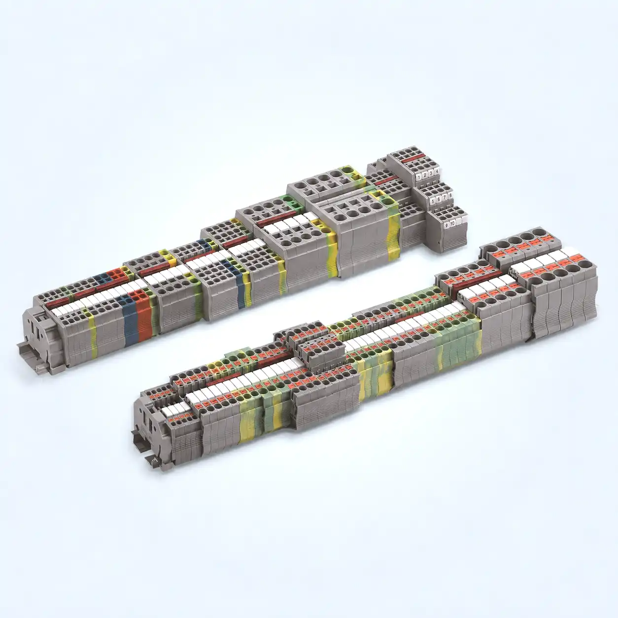
Electrical drawing
Defines circuit intent, device tags, potentials, conductor references and connection boundaries.
Do not count terminal symbols and call the result a bill of materials. Freeze the drawing revision, build a neutral position-and-level inventory, map it to exact physical housings, add compatible accessories, and preserve traceability through purchasing.
First, freeze the released drawing set and create a neutral record for every strip, position, level and connection boundary. Record the function, potential, conductor data, jumper group, destination side and spare status before selecting a terminal family.
Second, group those records into exact physical housings. Select compatible terminals, end plates, partitions, jumpers, markers, end stops and DIN rail. Verify ratings and the assembled line-up. Preserve every source position while rolling identical order numbers into purchasing lines.
A terminal-symbol count by itself is not a BOM. The same symbol count can produce different physical quantities when the design uses multi-level housings, multiple clamping points, field-wiring limits, open sides or product-specific accessory rules.
Keeping these artifacts separate prevents a wiring list from being mistaken for a procurement release.
Defines circuit intent, device tags, potentials, conductor references and connection boundaries.
One neutral record per position, level or boundary, with drawing coordinates and revision traceability.
Shows the ordered physical arrangement on each strip, including type transitions and fitted spares.
Adds connection-point, destination, conductor and jumper information to the strip structure.
Lists exact order numbers, quantities and units, plus assembly, marker and jumper documentation.
Why the distinction matters: EPLAN treats a terminal line-up as a list of terminals and a terminal diagram as a richer report with structure and connection-point data. Neither becomes an approved purchasing BOM until product mapping, accessory completion and release checks are finished.
Each stage has a different output. Do not aggregate part numbers until the physical line-up has passed its checks.
Start with an approved source package, not a collection of convenient PDFs. Record the project identifier, drawing number, revision, release status and effectivity. Identify which panels, terminal strips and enclosure locations are inside the BOM. State whether the release includes rail, labels, wire-end preparation, test accessories and loose spares.
Use the same released schematic, terminal plan, I/O list, cable schedule and equipment specification. Log every approved deviation.
Define strip tags, enclosure locations, mounting rail and interfaces to cables, devices and other panels.
Clarify assembled strip, loose parts, cut rail, marker printing, packaging, documentation and factory-wiring expectations.
Release rule: Put the same project identifier, revision and effectivity on the BOM, terminal diagram, jumper chart, assembly drawing and marking data. After release, issue a controlled revision or a formal no-BOM-effect disposition. Never silently combine artifacts from different revisions.
The inventory is intentionally manufacturer-neutral. It represents what the drawing needs, not what a favored catalog can supply. One row normally represents a unique connection level, terminal position or functional boundary. It does not automatically represent one purchasable terminal block.
| Field | What to record | Why it matters later |
|---|---|---|
| Source | Drawing number, sheet, grid, revision and effectivity | Provides bidirectional traceability and controlled change review. |
| Location | Panel, enclosure, strip tag, position and level | Separates identical-looking circuits in different physical line-ups. |
| Function | Feed-through, PE, functional earth, shield, fuse, disconnect/test, distribution or spare | Drives terminal construction and accessory requirements. |
| Potential | Voltage class, signal name, jumper group and separation boundary | Controls commoning, partitions, spacing and marker logic. |
| Connections | From/to destinations, internal/external side and conductors per clamping point | Prevents symbol count from hiding a wires-per-connection problem. |
| Conductor | Material, class, cross-section/AWG, quantity and intended termination | Supports exact conductor-range and field/factory-use checks. |
| Electrical duty | Current path, voltage, fault relevance, environment and required approvals | Identifies the rating gates that product selection must pass. |
| Status | Used, fitted spare, unused level, future, deleted or review required | Keeps physical spares distinct from reserved rail space and unused cable cores. |
Keep terminal-strip tags and position references consistent with the released drawing. A practical record may look like X1:12-L2, but the format must follow the project’s designation rules. If the scheme is not yet controlled, use the terminal block numbering and labeling guide before building the purchasing roll-up.
Internal versus external is not a certification decision. In a CAE terminal editor, those labels describe destination sides. They do not prove that a terminal is suitable for field wiring. For a North American panel, confirm the exact certification record and Conditions of Acceptability for the intended factory- or field-wiring duty.
A feed-through connection, a fuse carrier and a disconnect/test function are different requirements. Likewise, protective earth, functional earth and cable-shield termination must not be merged because they share a color or rail location. Give each inventory row one explicit engineering function.
A continuous connection between defined points. The exact product controls conductor count and clamping arrangement.
A PE terminal intended for protective-conductor duty, with a verified rail-to-enclosure bonding path.
An operational reference that may not satisfy protective-bonding requirements. Keep its intent explicit.
A cable-shield connection selected for the EMC design, shield size and mounting arrangement.
A product for the specified fuse system, current path, indication option and access condition.
A documented switching/test function. Ordinary feed-through terminals do not create service isolation.
A common incoming potential feeding multiple independent rated outgoing connection points.
A separately defined fitted housing, unused level or reserved physical space—not one generic percentage.
PE rule: Color alone is not evidence of a compliant protective-earth connection. Verify the exact PE terminal, compatible DIN rail profile and finish, rail current capability where relevant, enclosure bond, hardware and project requirements. Do not merge protective earth, functional earth and shield functions unless the electrical design explicitly joins them.
Only now should the neutral records be mapped to a manufacturer, product family and complete order number. Verify conductor material and class, cross-section, stripping and termination method, number of conductors per clamping point, current and voltage data, temperature conditions, approvals, environmental constraints and required accessories.
Three electrical levels may fit into one three-level housing, or they may require separate products because of potential separation, conductor routing, disconnect functions or marking constraints. Record the mapping explicitly: inventory rows X1:10-L1, L2 and L3 may map to one housing, but they remain three traceable electrical records.
If the drawing assigns more conductors to a clamping point than the exact terminal allows, the CAE layout or engineering review may need an extra terminal or a purpose-built distribution arrangement. Autodesk documents that Terminal Strip Editor can add terminals when a wires-per-connection limit is exceeded, and those added terminals become BOM items.
Use the dedicated guide on two wires in one terminal block when a symbol appears to combine conductors. Physical space is not permission.
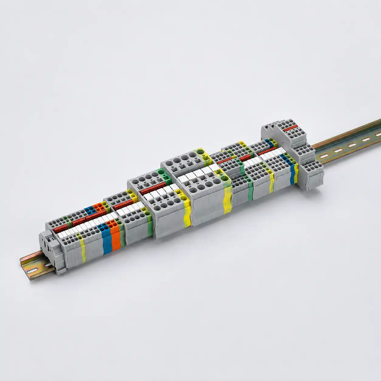
Do not copy a standard scope into a product rating. IEC 60947-7-1 defines requirements for applicable terminal blocks, but exact current, voltage, conductor and installation data must come from the selected product record. A terminal rating also does not establish the fault rating or SCCR of the completed panel.
For a disciplined model comparison, use SENTOP’s terminal block specification examples and the broader terminal block selection guide. Keep the BOM workflow focused on evidence and traceability rather than recreating the whole selection process.
Accessories are exact-system components, not generic add-ons. A shared brand name does not prove that an end plate, bridge, marker or end stop fits the chosen terminal family and variant. Build the ordered line-up first, then apply the current accessory documentation to every open side, product transition, commoning group and rail end.
Some terminal housings have an open side that must be closed. Type transitions can create additional open boundaries. The result may be zero, one or several end plates within one strip. Do not derive the count from the number of terminal positions.
A DIN-rail line-up may need one or two end stops, or another approved retaining arrangement, depending on orientation, rail and product instructions. Include type, quantity and location in the assembly data.
Add separators or partitions where the selected system requires potential separation, visual grouping or spacing. Do not assume a plastic separator creates a required creepage or clearance distance unless exact documentation supports that configuration.
| Item | Count from | Verification gate | Common mistake |
|---|---|---|---|
| End plate | Open sides and type transitions | Exact terminal variant and orientation | Assuming one plate per strip |
| End stop / bracket | Rail layout and restraint arrangement | Rail profile, orientation and product instructions | Automatically entering two |
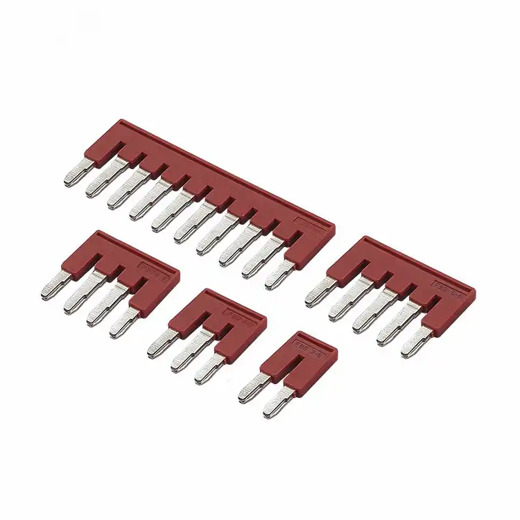
| Jumper / bridge | Potential groups and skipped positions | Family, pitch, poles, current, voltage and approvals | Copying the terminal current rating |
| Partition | Potential, family and spacing transitions | Documented insulation/spacing contribution | Using it as an unverified clearance fix |
| Marker | Legend set and marking medium | Carrier, pitch, print system and readable location | Equating one marker card with one terminal |
| DIN rail | Physical line-up length plus approved allowances | Profile, material, finish, mounting and stock/cut rule | Buying only the summed terminal width |
| Test / special part | Exact test or disconnect architecture | Product system and procedure | Treating a loose accessory as a universal test point |
A jumper is a current-carrying catalog part, not merely a line on the drawing. Verify the terminal family, channel and pitch, pole pattern, skipped positions, rated current and voltage, approvals, ambient conditions and every outgoing load. The commoned path is limited by its most restrictive approved element; never copy the terminal block’s current rating onto the bridge without evidence.
For a deeper explanation of each accessory’s purpose, see end plates, jumpers and markers explained. The product-level terminal block accessories page can support an RFQ after the exact family is known.
Once the line-up is complete, roll identical manufacturer order numbers into BOM lines. Keep a separate mapping table from each strip position and accessory location to the aggregated line. This lets engineering answer where every purchased item is used and lets production report a shortage against the affected positions.
The number physically installed in the released line-ups, with usage references and exact configuration.
The quantity ordered after pack size, card size, stock length, MOQ and approved rounding are applied.
Every aggregated part number links back to strip, position, level, accessory location and source drawing.
| BOM field | Required content | Release purpose |
|---|---|---|
| Role | Terminal, end plate, bridge, marker, end stop, rail or special accessory | Supports checks by function rather than description alone. |
| Manufacturer / order number | Complete current order code with variant and color where relevant | Prevents family-level or shorthand ordering. |
| Description | Controlled plain-language description | Helps review, but never replaces the exact order number. |
| Assembly quantity | Required fitted quantity and installation UOM | Supports production and line-up reconciliation. |
| Purchase quantity | Order quantity, purchasing UOM, pack size, MOQ and rounding basis | Prevents cards, strips and stock lengths from being ordered one-for-one. |
| Source / usage | Strip-position ranges, drawing reference and accessory locations | Preserves the bidirectional check after aggregation. |
| Evidence | Data-sheet revision, approval record and Conditions of Acceptability where relevant | Shows which source supported the selected configuration. |
| Status | Released, approved alternate, hold, obsolete review or deviation | Prevents uncontrolled substitutions. |
Spare policy: Do not apply a generic spare percentage. State separately how many spare terminal housings are fitted, which unused levels remain available, how much rail length is reserved, which legends are pre-marked and whether spare cable cores are included. Reserved rail space is not a fitted spare. A fitted spare may still need a marker, end plate, partition or safe potential boundary.
A useful review can start from the drawing and reach every BOM item. It can also start from any purchase line and return to its strip positions and source requirements. This bidirectional check exposes missing accessories, orphaned parts and changes that bypassed the drawing.
Confirm function, conductor data, current path, voltage, jumpers, PE/bonding, separation, environment, approvals and fault-duty relevance.
Rebuild the ordered line-up from the BOM. Check housing widths, levels, open sides, partitions, end hardware, rail length, access and marking locations.
Match drawings, terminal diagram, assembly view, jumper chart, marking data, BOM, product evidence, revision and effectivity.
Confirm order codes, lifecycle, approved alternates, UOM, pack rounding, stock length, supply scope and acceptance documents.
Finished-panel boundary: A CAE plausibility check, product standard, terminal certification or catalog rating does not certify the completed panel. The responsible designer or panel builder still verifies the assembly, protection, fault duty, environmental conditions and governing end-product requirements.
This example shows the method only. It contains no real part numbers, product ratings or universal spare allowance.
X1 contains six feed-through positions. X1:1–3 share one potential. X1:4–6 remain separate. X1:7 is a PE point. X1:8–9 are project-defined fitted spares. The line-up is mounted on one rail segment and requires markers and retaining hardware.
| Requirement records | Physical mapping | Accessory or purchase effect | Release note |
|---|---|---|---|
| X1:1–3 feed-through One common potential | Three approved connection positions in the selected family | One exact three-pole bridge only if the family supports that pitch and pattern | Verify total outgoing load against the bridge rating. |
| X1:4–6 feed-through Independent potentials | Three connection positions, possibly separate or grouped in housings | No bridge; add partitions only where exact documentation requires them | Keep each position traceable after part aggregation. |
| X1:7 PE | One exact PE terminal compatible with the rail system | Bonding path and rail requirements become validation items | Green/yellow color alone is not approval. |
| X1:8–9 fitted spares | Two installed housings or levels as defined by project policy | May require legends, open-side closure or separation | Do not confuse them with reserved empty rail space. |
| Complete sequence | Ordered physical line-up | End plates, end stop(s), markers and rail derived from the arrangement | Counts are exact-system and layout dependent. |
Aggregation result: identical terminal order numbers may become one purchasing line, but the usage mapping must still name X1:1 through X1:9. Marker cards and DIN rail stock lengths use their own units and pack rules; they do not become nine pieces because the strip has nine positions.
AutoCAD Electrical, EPLAN and manufacturer configurators can accelerate terminal reports, layout, accessory selection, marking and BOM export. They work best when the source data, product database and connection rules are controlled.
Confirm exact product evidence, field/factory suitability, PE bonding, jumper loading, environmental conditions, fault relevance, enclosure constraints, approved alternates and final assembly rules. A green software status is not a conformity certificate.

Each shortcut removes information needed by engineering, production or purchasing.
Symbols describe electrical intent. Multi-level grouping and wires-per-clamp limits can change the physical housing quantity.
Forcing the inventory into a preferred catalog can hide conductor, function or approval gaps.
Accessories must match the exact family, variant, pitch and adjacency. A shared logo is not enough.
Fitted spares, unused levels, reserved rail length, spare legends and cable cores are different project decisions.
Marker cards, jumper combs, rail stock and packaged accessories rarely equal one terminal position each.
An updated drawing with an old jumper chart or label file can produce an apparently complete but incorrect strip.
Safety boundary: Selection, assembly, testing and field wiring must be completed or reviewed by qualified personnel under current product instructions and the project’s de-energization and lockout/tagout procedure. This BOM workflow does not authorize energized work or provide terminal installation, jumper fitting, fuse handling or torque instructions.
A useful RFQ lets the supplier verify the terminal family, accessories, markings and commercial unit without guessing the electrical intent.
No. Symbols describe electrical requirements, not necessarily physical housings. Multi-level terminals can group several records into one part, while wires-per-connection limits, open sides and special functions can add terminals or accessories. Build the neutral inventory and physical line-up before aggregating parts.
A line-up records the ordered terminals in a strip. A terminal diagram adds connection-point, destination, conductor and wiring information. A released BOM is a separate procurement artifact with exact order numbers, quantities, units, evidence and traceability.
Not automatically. Several electrical levels can belong to one physical housing. Keep one inventory record per level or connection boundary, then explicitly map those records to the selected housing. The product, routing, marking and separation requirements control the result.
Count them from the exact assembled sequence and product documentation. End plates follow exposed sides and type transitions, so a strip may need zero, one or several. Do not use one end plate per strip as a universal rule.
No universal quantity applies. The rail, orientation, terminal arrangement and manufacturer instructions determine whether one, two or another approved retaining method is required. Record the chosen end hardware and its location in the assembly data.
Only if exact product evidence states it. A jumper is a separate current-carrying part with its own family, pitch, pole pattern, voltage, current and use conditions. The commoned path is limited by its most restrictive approved component and actual outgoing loads.
There is no universal percentage. The project should define fitted spare housings, unused levels, reserved DIN-rail space, spare marker legends and unused cable cores separately. These choices have different BOM, layout and acceptance effects.
No. They are documentation assignments for connection destinations. Check the exact terminal certification record, conductor data and Conditions of Acceptability for factory- or field-wiring use, plus the requirements governing the completed equipment.
No, unless the electrical design explicitly makes them the same function. A PE terminal must be intended for protective-conductor service and requires a verified bonding path. Functional earth and shield termination serve different operational or EMC purposes.
Release the governing drawing references, terminal inventory or diagram, ordered line-up, BOM, jumper chart, assembly drawing, marking data, product evidence and revision/effectivity record. Purchasing also needs UOM, pack-size or stock-length rules and approved-alternate status.
Use the current product page, certification record and project requirements for every final selection.

