
7 Proven Applications for Multi-Level Terminal Blocks
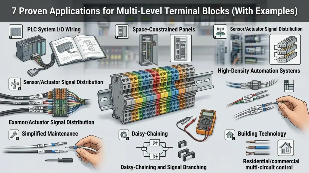
Multi-level terminal blocks work best when several conductors repeatedly belong to one device or function—such as signal, supply and return. The stacked layout can reduce rail length and make a terminal plan easier to read, but only when every tier, bridge, spacing and approval is selected from the exact product data.
Choose the circuit grouping first. Tier count is a packaging decision—not a shortcut for current, voltage, isolation or safety compliance.
The short answer
Use a multi-level terminal block when conductors can be organized by device or circuit function without compromising ratings, separation, access or documentation. A good design makes the wiring logic clearer as the rail becomes denser.
What a multi-level block actually changes
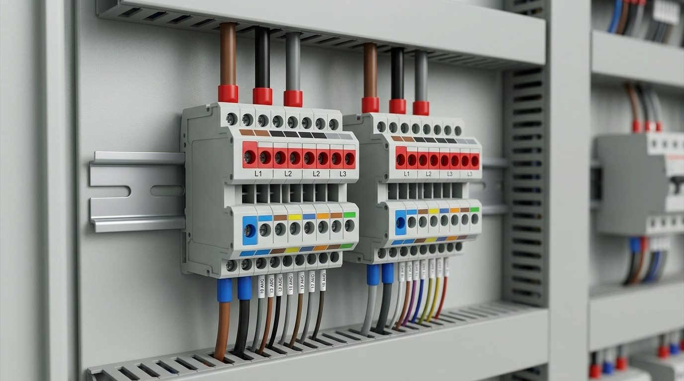
A multi-level terminal block combines two or more terminal functions vertically on one DIN-rail position. It changes the physical arrangement of the wiring; it does not erase the electrical rules that apply to each circuit.
A standard feed-through level provides a conductive path between its approved connection points. On a double-level block, the upper and lower paths are commonly independent. Some product families add vertical bridges, cross-connection channels, disconnect zones, fuses, LEDs, diodes, test points or a protective-conductor function. Those features must be read from the circuit diagram for the exact part number.
The strongest application pattern is one field device, one vertical terminal position. A three-wire sensor, for example, may be mapped to signal, supply and return. The schematic, terminal plan and physical labels can then use the same position number with clear level suffixes.
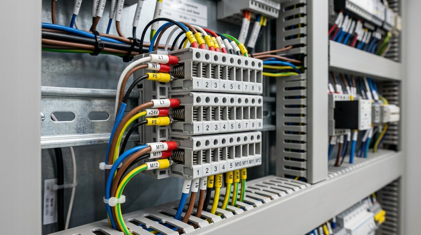
A normal feed-through level does not become a PE connection because it is mounted near the rail. Use a terminal specifically designed and approved for protective-conductor service, with the specified rail, end brackets and installation method.
Two, three and four levels: choose by function
More levels do not inherently mean lower or higher current capacity. Housing geometry, conductor range, connection technology, insulation design and approvals determine the rating of each model.
Two independent paths
A compact starting point for paired conductors, two circuits from one device, or feed-through plus a product-specific function. Verify whether vertical bridging is possible or intentionally blocked.
Signal, supply and return
Common in sensor and actuator wiring. A function-specific version may combine signal with distributed positive and negative potentials, but the actual level order is not universal.
Four related conductors
Useful for selected multi-wire devices or compact motor/sensor functions when the model supports the required conductor sizes, access, bridges and heat-rise conditions.
Fuse, disconnect, test or PE
Functional tiers can simplify commissioning and maintenance. Confirm their symbols, commoning, replaceable components, test method and separate accessory ratings before release.
“Three-level” describes the physical stack, not a universal L/N/PE or +/signal/− circuit. Two blocks with similar housings can have different internal connections and approved functions.
Seven applications at a glance
Treat these configurations as engineering starting points. The final terminal strip must follow the circuit drawing, exact model data, end-equipment standard and destination-market requirements.
| Application | Natural circuit group | Useful starting point | Critical verification |
|---|---|---|---|
| PLC I/O | Signal, sensor supply, return | 3-level sensor/actuator or disconnect terminal | Channel commoning, fusing, PNP/NPN logic, bridge layout |
| Instrumentation | Loop conductors, RTD leads, shield function | 2–4 levels with disconnect/test where needed | Intrinsic safety, thermocouple material, shield/PE method |
| Motor control | Motor phases/PE or coil/feedback auxiliaries | Purpose-built motor block or grouped auxiliaries | Current, fault duty, temperature, spacing, approvals |
| HVAC/BAS | Power, common and control per field device | 2–3 levels with protected common distribution | Communications routing, class separation, service access |
| Machine tools | Sensors, solenoids, drive I/O, safety channels | 2–3 levels plus PE/disconnect functions | EMC plan, safety architecture, machine standard |
| Rail/transit | Door, lighting, HVAC and monitoring circuits | Qualified spring or push-in multi-level family | Exact shock, vibration, fire, temperature and project tests |
| Solar/BESS | Auxiliary sensing, temperature and communications | Function-specific low-energy signal grouping | Isolation, system voltage, fault energy and system standard |
PLC I/O and control cabinets
Best fit: repeated sensor and actuator channels
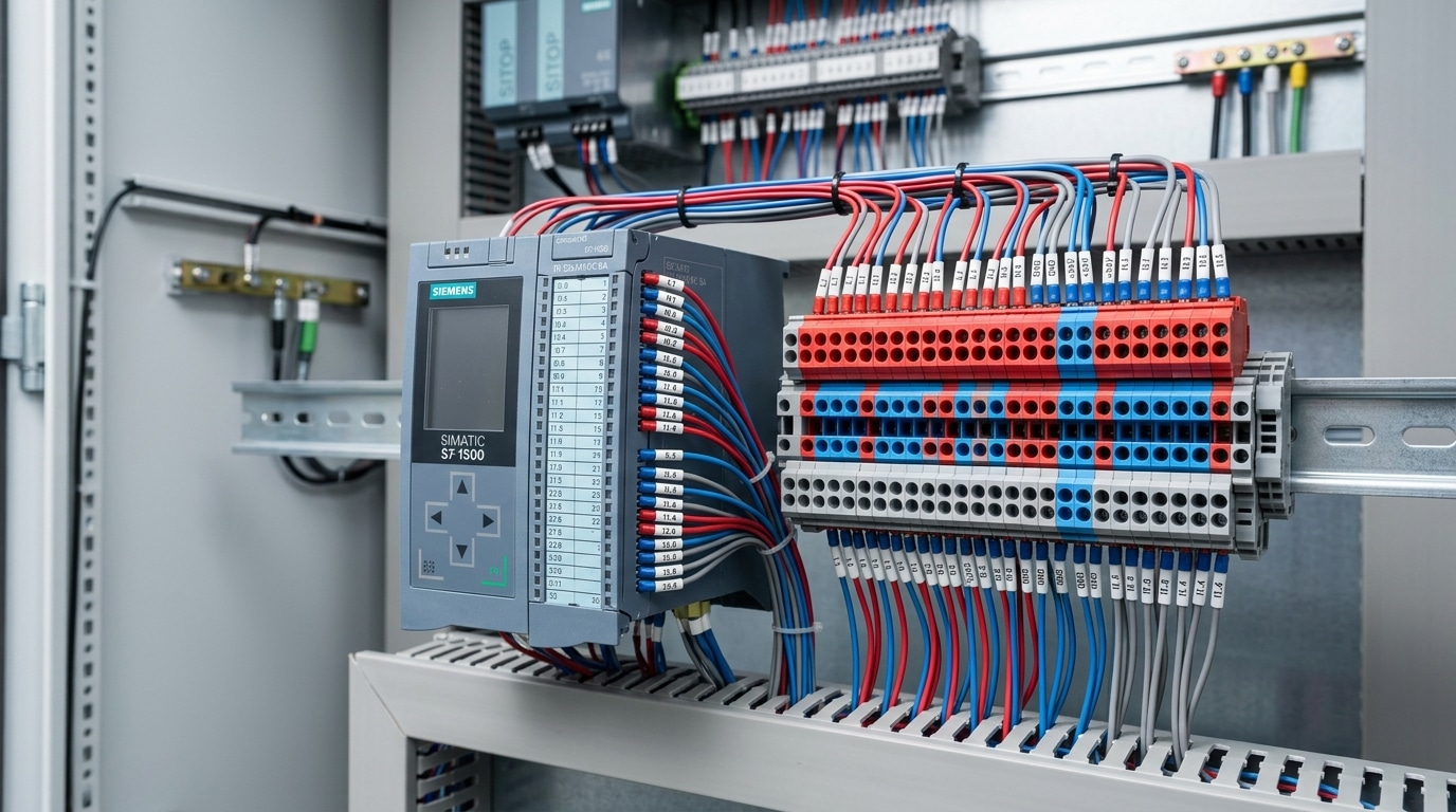
PLC marshalling is the clearest multi-level terminal block application because each I/O point often repeats the same small group of conductors.
For a three-wire DC sensor, a function-specific sensor terminal can keep its signal, supply and return at one terminal position. Bridged supply levels may distribute +24 VDC and 0 VDC across a channel group while each signal remains independent. Disconnect or test versions can help commissioning teams isolate a field point without disturbing adjacent wiring.
The circuit design still controls the layout. Confirm whether inputs are PNP or NPN, how the PLC module commons are arranged, where branch protection is provided and which potentials the factory bridge connects. Check the bridge’s own current rating rather than assuming it equals the terminal’s through-current rating. Leave space for group separation, end plates, markers and any fused or disconnect terminals.
A workable PLC channel map
- Group by device: one terminal position per sensor or actuator.
- Assign by drawing: signal, supply and return order follows the chosen block.
- Protect distribution: size fuses, bridges and conductors as a complete circuit.
- Keep safety distinct: do not combine safety and standard I/O merely to save rail.
Process instrumentation and field enclosures
Best fit: multi-wire instruments and loop marshalling
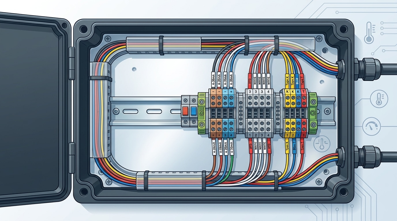
Compact junction boxes benefit when the conductors for one transmitter, RTD or analyzer can occupy adjacent levels and remain easy to disconnect, test and identify.
A two-wire 4–20 mA loop may need two feed-through paths and a shield termination strategy. A three-wire RTD needs three matched circuit paths. Some instrument loops also benefit from knife-disconnect, fuse, diode or test-point functions. Multi-level blocks can keep these related points together, reduce crossovers and create a clean marshalling pattern from field cable to I/O cable.
Instrumentation introduces limits that density must not hide. Intrinsically safe and non-intrinsically safe circuits require the separation, identification and installation practices defined by the applicable system design. Thermocouple circuits need compatible connection materials and cold-junction treatment; a generic copper feed-through is not automatically suitable. Cable shields may terminate at an insulated shield bar, PE function or another documented point depending on the EMC and grounding plan.
Motor control and MCC interfaces
Best fit: purpose-built motor terminals and compact auxiliary circuits
Motor circuits are a valid application only when the terminal is designed for the conductor size, current, voltage, temperature and fault conditions involved.
Purpose-built multi-level motor terminals can group motor conductors and a protective-conductor function in one documented assembly. In many MCCs, however, the better high-density opportunity is the auxiliary interface: contactor coil, run feedback, fault contact, thermal sensor and local/remote control wiring. These lower-energy circuits repeat by starter and can be organized vertically without forcing the main feeder through a general-purpose signal block.
Do not assume that stacking L1, L2 and L3 in a generic housing is acceptable, or that a high voltage marking alone establishes suitability. Verify conductor range and preparation, continuous current, adjacent loading, heat rise, short-circuit coordination, spacing, branch protection, PE function and the panel’s required certification. Power and control circuits may need dedicated partitions, separate terminal groups or greater physical separation under the applicable equipment and wiring rules.
Select the exact terminal from calculated circuit requirements and its certified data. For larger conductors, high fault energy or frequent field work, a single-level power terminal may be safer and easier to service.
HVAC and building automation
Best fit: repeated field devices by zone
VAV controllers, damper actuators, valves and duct sensors frequently repeat a supply, common and control or feedback conductor—an intuitive match for a vertical terminal slice.
A two- or three-level strip can place all terminations for each zone in sequence, with approved jumpers distributing a protected common or supply. The approach makes expansion points visible and can reduce wire crossings between the terminal strip, controller and wire duct. It is especially useful when technicians troubleshoot by device tag rather than by a long list of unrelated terminal numbers.
Do not treat the tiers as electromagnetic shielding. BACnet MS/TP, Modbus and other balanced communications must preserve the cable manufacturer’s pair geometry, polarity, shield treatment, topology and termination requirements. Keep switching loads and noisy circuits routed according to the controls manufacturer’s instructions. Confirm whether different circuit classes may occupy the same device or terminal group, and add partitions or separate strips where the project specification requires them.
What makes a serviceable BAS strip
- Zone or equipment tag is visible from the panel door.
- Each level has a documented suffix, color or marker.
- Commoning and branch protection are shown on the schematic.
- Technicians can probe the test point without removing adjacent wires.
CNC and machine-tool wiring
Best fit: sensors, solenoids, drive I/O and defined safety interfaces
Machine panels combine high channel counts with demanding service access, making multi-level blocks useful for repeated low-voltage field devices and carefully separated functions.
Limit switches, tool-change sensors, solenoid valves and drive-control signals can be grouped by device. Disconnect levels support commissioning, while PE or shield accessories can provide a documented termination point when the product and grounding design permit it. The terminal plan should mirror the machine electrical documentation required for construction, maintenance and troubleshooting.
Stacked tiers do not solve EMC by themselves. Drive-cable routing, cable type, shield bonding, grounding, separation distance and the drive manufacturer’s installation instructions still determine performance. Follow the machine electrical-equipment requirements and the power-drive-system EMC plan. Keep safety channels, test points and reference potentials aligned with the validated safety architecture; do not share a common merely because an insertion bridge is available.
The terminal provides an approved connection. Shield clamps, PE bonding, cable routing, enclosure design and filter installation control the wider interference path.
Railway, transit and mobile equipment
Best fit: compact equipment with documented environmental qualification
Door systems, passenger information, lighting, HVAC and monitoring assemblies can benefit from vertical circuit grouping where enclosure depth and rail length are tightly constrained.
Spring or push-in connections are often considered because their contact force is not set by an installer-applied screw torque, but connection technology alone does not establish railway suitability. Select a complete terminal family—including bridges, end plates, markers and mounting hardware—with evidence for the project’s required mechanical and environmental conditions.
IEC 61373 defines shock and vibration testing for equipment intended for railway vehicles, with conditions tied to equipment location and category. EN 45545-2 evaluates fire behavior requirements for materials and components used on railway vehicles. Neither standard is a universal “rail certification” for an entire vehicle, and neither supports a generic vibration, temperature or service-life claim for every terminal block.
Solar and battery energy storage
Best fit: auxiliary sensing, monitoring and communications
Renewable-energy equipment contains many compact auxiliary circuits, but its high system voltages and fault energy make careful scope definition essential.
Within a combiner, inverter auxiliary cabinet or battery management enclosure, multi-level blocks may organize current-sensor outputs, temperature sensors, interlocks, power supplies and communications. Disconnect or test functions can help isolate monitoring circuits during commissioning. Device-by-device grouping also makes module and string identifiers easier to trace—provided the terminal plan and labels stay synchronized.
Do not infer suitability for a 1000 VDC or 1500 VDC power circuit from a family name or a general catalog statement. Verify the exact rated voltage, impulse withstand, creepage and clearance conditions, pollution degree, conductor range, current, fault duty and product approval for the installed circuit. Preserve twisted-pair geometry and isolation for CAN or RS-485. For battery systems, IEC 62619 provides safety requirements and tests for industrial secondary lithium cells and batteries; it does not prescribe a multi-level terminal topology.
In some terminal-block descriptions it refers to potential or vertical bridging, not photovoltaic suitability. Only the exact datasheet and certification establish use in a solar power circuit.
Build the terminal strip from the circuit map
A reliable selection starts with one row per conductor and ends with an installed BOM. It does not start with a generic “two-tier” or “three-tier” current table.
Map every conductor
Record device tag, function, source/destination, potential, AC/DC, current, voltage, safety classification and required isolation.
Choose the function
Define feed-through, PE, disconnect, fuse, sensor distribution, test or diode/LED needs before choosing level count.
Check electrical data
Use the exact model’s ratings, conductor table, adjacent-loading data, bridge limits and insulation conditions.
Check the environment
Confirm temperature, pollution, vibration, altitude, humidity, corrosion, enclosure and destination-market requirements.
Model the installed geometry
Add terminal widths, end plates, partitions, end brackets and spare positions; then verify height, depth and wire-duct access.
Complete the accessory plan
Specify every jumper, marker, test plug, partition, fuse, rail and tool as compatible part numbers.
Compare rail length with a real BOM
For each design, total the quantity multiplied by the installed width, then add end plates, partition plates, end brackets and planned spare positions. A three-level block can theoretically replace three single-level positions only when the functions, wire sizes, ratings, accessories and service access are genuinely equivalent. Report the result from your BOM rather than publishing a universal space-saving percentage.
| Connection method | Useful selection driver | Verify on the exact model |
|---|---|---|
| Screw clamp | Established workflow, broad application familiarity | Torque range, conductor preparation, maintenance instructions and tool access |
| Spring cage | Spring-applied contact force and varied conductor handling | Actuation method, ferrule requirements, insertion/withdrawal steps and environmental qualification |
| Push-in | Fast direct insertion of approved conductors in repetitive OEM work | Approved solid/ferruled ranges, push-button use, strip length and fine-stranded preparation |
Installation and validation checks
Dense wiring increases the value of disciplined preparation, labeling and inspection. Use the manufacturer’s instructions for the exact terminal, conductor and accessory combination.
Strip and terminate correctly
Use the specified strip length, ferrule policy, conductor type and cross-section. For screw terminals, apply only the stated torque with a suitable controlled tool.
Label every level
Give each tier a unique terminal designation and show it on the schematic, terminal plan and wire markers. Color can assist identification but should not replace text.
Install barriers and end plates
Fit all required partitions, end plates and covers. Confirm that adjacent circuits meet the applicable insulation and wiring-separation requirements.
Test the intended circuit
Inspect conductor insertion, bridge placement and PE bonding, then perform the continuity, insulation and functional tests required by the equipment procedure.
Record exact part numbers, level assignments, bridge positions, marker text, accessory locations and revision status. This prevents a visually similar replacement from changing the circuit later.
When a single-level terminal block is the better choice
The densest terminal strip is not automatically the best terminal strip. Choose single-level blocks when visibility, access, conductor size or separation matters more than rail length.
Large conductors or high fault energy
Dedicated power terminals may offer clearer routing, heat management, covers and service access for demanding circuits.
Different circuit classes
Separate groups can make voltage, safety or intrinsic-safety boundaries easier to design, inspect and maintain.
Frequent probing or rewiring
A single row gives direct tool access and may reduce the risk of disturbing an adjacent level during service.
Limited vertical clearance
Deep wire ducts, small bend space or a shallow door can make a tall stacked block impractical even when rail space is available.
Also keep the single-level option when the required bridge, marker, fuse, test plug or certification is unavailable in the multi-level family. A constructability review with the panel builder and maintenance team often exposes these issues before procurement.
Send the circuit map—not just the tier count.
SENTOP can match multi-level terminals and compatible accessories from your schematic, terminal list or existing model. Include the function of every level so the proposal can be checked as a complete terminal strip.
Products and selection resources
Review connection technologies, DIN-rail families and the accessories that complete the installed terminal strip.
Spring Terminal Blocks
Explore double-level and multi-level signal-wiring options with spring connection technology.
View the range → Product familyDIN Rail Terminal Blocks
Compare feed-through, PE, disconnect, fuse and other DIN-rail terminal functions.
Explore DIN-rail blocks → Complete the stripTerminal Block Accessories
Plan compatible jumpers, markers, end plates, partitions, end brackets and testing parts.
Choose accessories → Engineering guideTerminal Block Selection Guide
Work through electrical, mechanical, conductor and environment requirements before ordering.
Open the guide →Build a more reliable terminal plan
Multi-level terminal block FAQ
Do all levels in a multi-level terminal block share electrical potential?
No. The levels are commonly independent unless the exact product diagram shows an internal connection or an approved vertical bridge is installed. Check the circuit symbol and accessory instructions for the part number.
How much DIN rail space can multi-level terminal blocks save?
There is no universal percentage. Compare two complete BOMs using terminal quantity and width plus end plates, partitions, end brackets, spare positions and service clearance. A stacked design saves space only when it performs the same approved functions.
Can 24 VDC and 120 VAC share one multi-level terminal block?
Only when the exact terminal, accessories, equipment standard and applicable wiring rules permit the arrangement. A voltage rating by itself is not enough; circuit separation, insulation coordination, identification and end-product requirements must also be satisfied.
Can a normal feed-through level be used as protective earth?
No. Use a terminal level specifically designed and approved for protective-conductor service, installed with the stated rail and hardware. A normal level does not become a PE connection simply because the housing is rail-mounted.
Do stacked terminal levels solve EMC or signal-noise problems?
No. Multi-level blocks can organize conductors, but they are not electromagnetic shields. Cable type, pair geometry, routing, separation, shield termination, grounding, filters and equipment instructions determine the EMC result.
When should I choose single-level terminals instead?
Choose single-level terminals when large conductors, high current or fault energy, frequent probing, strict circuit separation, limited vertical clearance, easier visibility or unavailable accessories make direct access more important than rail density.
Standards and manufacturer references
Use the current edition required by the project and the exact manufacturer documentation for the selected part number.
- IEC 60947-7-1:2025 — terminal blocks for copper conductors; scope and product requirements.
- IEC 60947-7-2 — protective-conductor terminal blocks.
- IEC 60664-1:2020 + AMD1:2025 — insulation coordination for low-voltage equipment.
- UL 1059, 6th edition — terminal blocks within its stated scope.
- Phoenix Contact — multi-level terminal construction and functional options.
- Phoenix Contact — sensor and actuator terminal functions.
- WAGO TOPJOB S — single through quadruple-deck product overview.
- Weidmüller — signal-wiring and multi-tier functional combinations.
- IEC 60204-1:2016 + AMD1:2021 — electrical equipment of machines.
- IEC 61800-3:2022 + COR1:2025 — EMC requirements for power drive systems.
- IEC 61373:2026 — railway rolling-stock equipment shock and vibration tests.
- EN 45545-2:2020 + A1:2023 — fire behavior requirements for materials and components on railway vehicles.
- IEC 62619:2022 — industrial secondary lithium cell and battery safety requirements.
- IEC 62548-1:2023 + AMD1:2025 — photovoltaic array design requirements, including DC wiring and protection context.
