
Terminal Block Accessories Explained: End Plates, Jumpers & Markers
Accessories are part of the terminal system, not generic add-ons. Match every end plate, end stop, jumper, marker and test part to the exact terminal family, catalog number, rail and installed configuration.
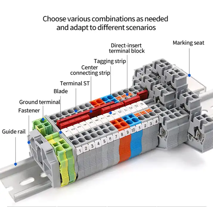
What are terminal block accessories?
Terminal block accessories are the matched parts that fix a terminal row to its rail, close open profiles, separate functional groups, distribute a common potential, identify connection points and provide defined test or service functions.
Begin with the terminal block manufacturer, family and full catalog number. Then verify the accessory part number, mounting orientation, rail profile, pitch, positions, ratings, environmental limits, certification conditions and installation method. A part that physically snaps in is not automatically electrically suitable or approved.
The most common categories are end plates or end covers, end brackets or end stops, partitions, jumpers or bridges, markers, test accessories, protective covers and the rail or mounting hardware. The names vary by manufacturer, so use the terminology in the current product catalog when preparing a purchase order.
For SENTOP sourcing, review the terminal block accessories range together with the selected terminal block family. Send the full terminal-strip plan rather than ordering accessories from a product photo.
End-product requirements still govern enclosure design, insulation coordination, conductor preparation, spacing, rail retention, short-circuit coordination, identification and qualified installation. For IEC, UL or Ex claims, verify the exact evaluated combination and all conditions of use.
Build the terminal strip as one engineered system
The base terminal provides the connection point. The accessory set completes the mechanical, insulation, distribution and identification plan.
Rail and end brackets
The specified DIN rail supports the blocks. End brackets, end stops or end clamps retain the row so it does not slide along that rail.
End plates and end covers
A series-matched plate closes an open side where the terminal design requires it and can be necessary to preserve published insulation or touch-protection performance.
Partitions and covers
Specified partitions can provide visual separation and, where documented, electrical separation from adjacent cross-connections or functional groups.
Jumpers and bridges
Approved horizontal, vertical, step-down or staggered bridges distribute a defined potential through the connection pattern shown by the manufacturer.
Markers and carriers
Matched markers identify terminal positions, circuits or customer codes using a defined slot, pitch, orientation and printing system.
Plugs, adapters and tools
Test plugs, service plugs, fuse plugs and operating tools are exact-system parts with their own ratings and permitted procedures.
Procurement rule: put the terminal blocks and all accessory part numbers on the same reviewed BOM. That makes compatibility, quantities and substitutions visible before panel assembly.
End plate, end stop and partition are different parts
These names were mixed together in the original draft. Separating their jobs prevents a mechanical fixing part from being mistaken for an insulation part.
| Part name | Main job | Usually matched by | Do not assume |
|---|---|---|---|
| End plate / end cover | Closes the specified open side of a terminal profile; may complete insulation and touch protection | Exact terminal family, profile, orientation, level count, thickness and color | That it clips to the DIN rail or mechanically retains the row |
| End bracket / end stop / end clamp | Retains the terminal row on the specified rail and resists sliding | Rail profile, terminal arrangement, mounting method and documented mechanical conditions | That it closes the terminal's open electrical profile |
| Partition / separator plate | Separates specified terminals, functional groups or cross-connection areas | Terminal profile, installed location, required spacing and approved assembly configuration | That any plate is a universal barrier between different voltages |
| Terminal cover / protective cover | Covers a defined terminal area or accessory opening where the system provides one | Exact terminal or function module, cover geometry and applicable rating | That every cover produces a universal IP20 or code-compliant result |
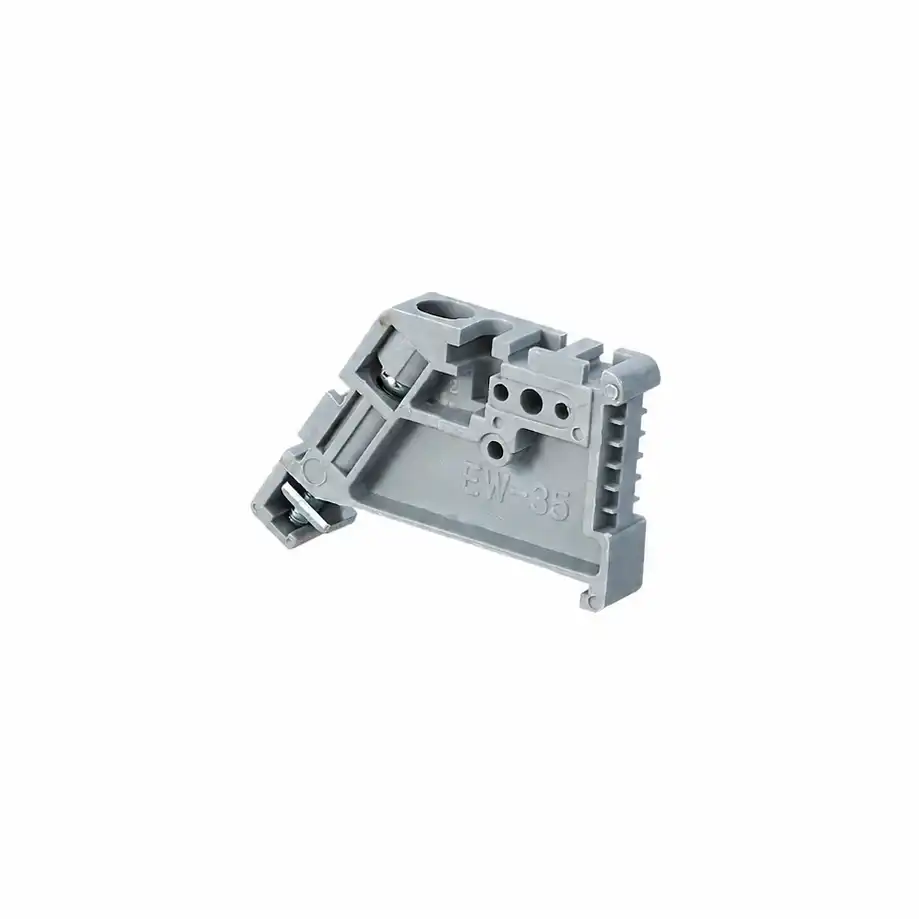
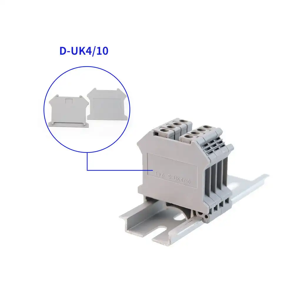
A terminal row can require both an end plate and an end bracket because they solve different problems. Follow the maker's assembly drawing instead of counting one part as a substitute for the other.
How to choose the correct end plate or end cover
Choose from the terminal's accessory table. Conductor size and a similar outline are not enough to establish compatibility.
Use the full catalog number
Record the manufacturer, product family, exact terminal code, width, color, connection level and any special function such as PE, disconnect or fuse.
Check orientation and profile
Confirm which side is open in the planned strip and whether mixed terminal types create another open profile that needs a different plate.
Insulation and assembly rating
Check whether the plate is required for the published voltage, touch-protection, creepage or clearance conditions of that specific configuration.
Levels, bridges and partitions
A multi-level, hybrid or bridged terminal can require a dedicated plate. Confirm that the end profile covers every required level and accessory area.
Color, thickness and environment
Record the approved material, dimensions, temperature or environmental limits and color required by the panel's identification plan.
Fit before volume release
For a new family, substitution or mixed strip, assemble the proposed blocks, plates, brackets, jumpers and markers before approving a bulk BOM.
Do not apply a generic spare percentage. Set spare quantities from the project maintenance plan, installed base, lead time, criticality and packaging quantity.
Jumpers and bridges: match the current path and geometry
Jumper, bridge and cross-connector are overlapping catalog terms. The manufacturer's exact part name, circuit diagram and rating table control the selection.
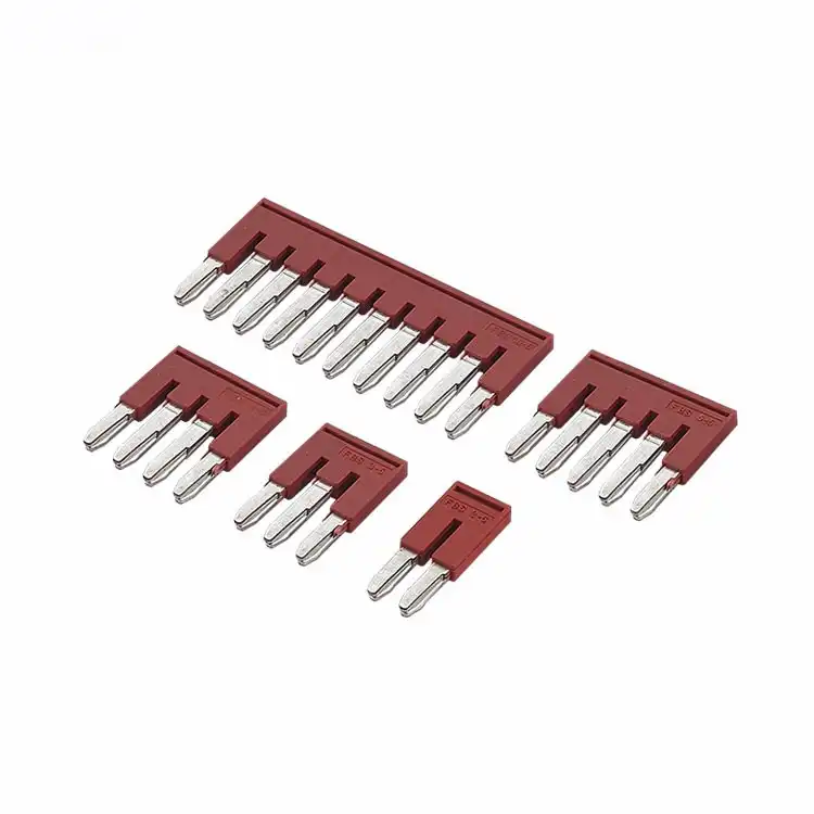
Select a manufacturer-approved bridge for the exact family, pitch and position count. Then apply the current, voltage, short-circuit and certification limits that apply to the installed bridge pattern. The limiting rating of the complete configuration governs.
- Exact terminal series and bridge channel
- Pitch and number of connected positions
- Horizontal, vertical, step-down or staggered pattern
- Bridge current and voltage in the installed configuration
- Insulation cover, partition or cut-edge treatment
- Approved tool and installation instructions
| Question | What to record | Why it matters |
|---|---|---|
| Which points share a potential? | Terminal positions, skipped positions, levels and circuit function | Determines pole count and whether an adjacent, staggered, vertical or reduction bridge is needed |
| Which geometry fits? | Terminal family, bridge shaft, pitch, insertion direction and tool | Physical fit across another family does not establish contact force or approval |
| What current flows through the bridge? | Total incoming current, branch paths, loading pattern and protection | The bridge can be the limiting current path even when the terminal accepts a larger conductor |
| Which rating applies? | Current, voltage, insulation, short-circuit and certification data for the actual pattern | Cut, skipped or mixed-size configurations can have different limits |
| Can it be shortened? | Permitted pole removal, cutting tool, edge cover and changed voltage limits | Cutting can reduce insulation distances or violate certificate conditions |
Some families come in fixed pole counts; others permit selected contact tabs to be removed or the bridge to be shortened with a specified tool and cover. Never cut a bridge or leave an exposed edge unless the exact instructions and certification conditions permit it.
Multi-level terminals can support horizontal commoning on one level, vertical connection between levels or another defined pattern. Use the terminal's bridge diagram; do not assume that a standard adjacent jumper creates a vertical or diagonal path.
Markers: match the terminal slot and the identification plan
A readable marker begins with the drawing designation and ends with media that remains legible in the real panel environment.
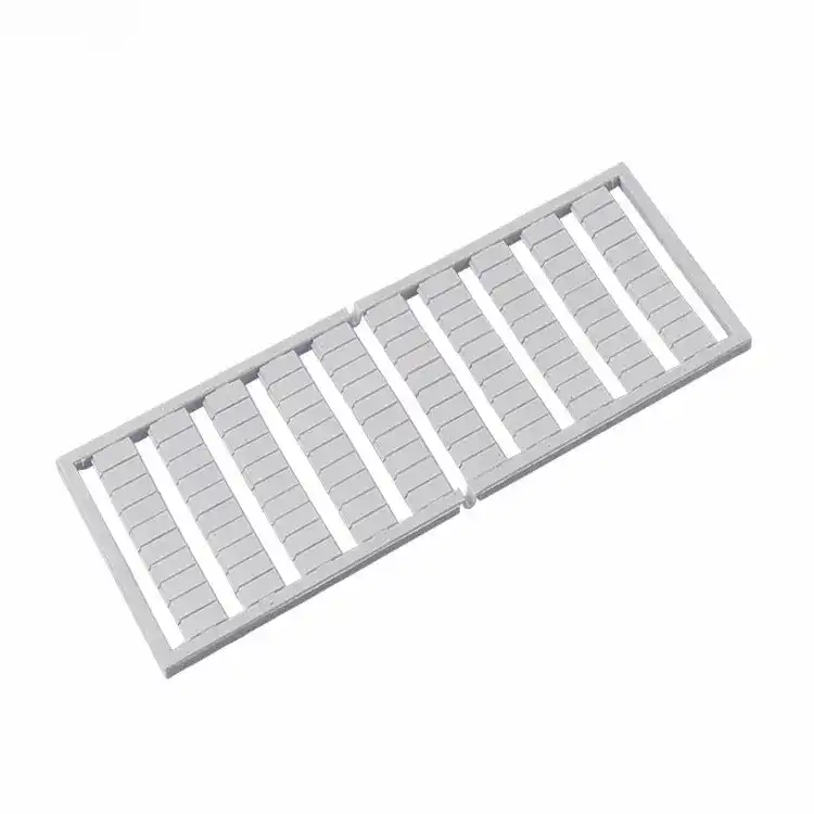
- Terminal: exact family, width, pitch and marker slot.
- Designation: terminal number, circuit, cabinet, device or customer code.
- Format: individual tags, strip, card, carrier or adhesive system listed for the use.
- Printing: preprinted, plotter, thermal-transfer, inkjet or another approved process.
- Environment: temperature, UV, oil, chemicals, abrasion, humidity and cleaning method.
- Workflow: file format, sequence, orientation, spare policy and revision control.
Do not assume that every third-party marker is unsuitable. Some marking systems are expressly listed for multiple brands. Compatibility still has to be verified from the marker manufacturer's table, pitch and product code, with a sample fit when the combination is new.
Other terminal block accessories you may need
Use these only where the selected terminal system provides the function and documents the installed combination.
Defined group separation
Separate selected terminals or cross-connection areas. Verify profile height, installed position, creepage, clearance and the resulting assembly rating.
Rated test interfaces
Use only with the exact test-disconnect terminal and within the accessory's own voltage, current, measurement-category and procedure limits.
System-specific modules
Treat fuse terminals, fuse plugs, disconnect plugs and current-distribution jumpers as separate functions. Use only listed combinations and fuse types.
Covers, sleeves and filler plugs
Close the openings identified by the product system. Confirm which rating or touch-protection condition each part supports in the installed state.
DIN rails and end brackets
Match the rail profile, length, material, mounting holes, end stops and terminal load. Material alone is not a vibration rating.
Operating tools and wiring duct
Include approved operating, insertion, cutting and printing tools, plus wiring duct dimensions and project packaging labels, in the BOM.
Never open a CT secondary while primary current is flowing. Use a documented make-before-break system or a test-disconnect terminal with a leading short-circuit contact so the CT secondary is shorted before the measuring circuit is disconnected. Energized testing is restricted to qualified personnel following the equipment and site procedure.
Match accessories in 6 controlled steps
Each step should leave a catalog number or documented open question. A blank field is not permission to guess.
Record every terminal block catalog number
Capture manufacturer, family, width, color, function, connection level, rail and conductor data. If the current block cannot be identified, supply clear side-profile, front, marking and rail photographs with dimensions.
Map positions, open sides and functional groups
Show the left-to-right terminal order, PE and neutral points, mixed families, multi-level functions, spare positions and every open profile. Mark where the row begins and ends on the rail.
Select rail, end brackets, end plates and partitions
Use the accessory table for each exact terminal family. Confirm which parts retain the row, which close open sides and which provide the required separation.
Map every shared potential and current path
Define connected positions, levels, skipped poles, branch currents and protective devices. Select exact bridge types, pole counts, covers and tools from the maker's diagrams and ratings.
Generate the marker file from the electrical drawing
Match marker pitch and carrier to each terminal. Record text, orientation, color conventions, media, printing process and the drawing revision that created the sequence.
Review ratings, approvals, quantities and a sample build
Check current, voltage, insulation, environmental and certification data for the installed combination. Count parts from the layout, add project-approved spares, and sample-fit new or substituted combinations before volume release.
Build the complete terminal-strip accessory BOM
Record one evidence line for every function. The supplier should be able to trace each proposed accessory back to the exact base terminal and configuration.
| BOM group | Record | Match by | Evidence to keep |
|---|---|---|---|
| Base terminals | Full catalog number, function, color and count | Conductor, circuit, rail, environment and approval requirements | Current datasheet, drawing and certificate conditions |
| DIN rail and end brackets | Rail profile, length, hole pattern, end-stop code and quantity | Terminal system, row load, mounting and environmental conditions | Rail and end-bracket product data plus layout |
| End plates / end covers | Part number, side, color, profile and quantity | Exact terminal family, orientation, level count and open-side locations | Accessory compatibility table and assembly drawing |
| Partitions and covers | Part number, installed positions and purpose | Profile, bridge area, spacing and protection requirement | Configuration-specific rating or instruction |
| Jumpers / bridges | Type, pitch, poles, positions, levels, covers and tools | Terminal family, current path, voltage and installed bridge pattern | Bridge diagram, rating table and cutting rules |
| Markers | Marker code, pitch, text, orientation, media and quantity | Marker slot, terminal width, printer and panel designation scheme | Compatibility table, print file and drawing revision |
| Test / function parts | Plug, adapter, fuse, disconnect or service accessory | Exact terminal system, function, own ratings and work procedure | Product instructions and qualified test procedure |
| Tools and delivery | Operating, cutting, printing tools; packaging and project labels | Manufacturer instructions and production workflow | Tool list, pack plan and approved substitution rules |

Substitution control: never approve an accessory substitution from a dimension or photograph alone. Recheck fit, electrical ratings, spacing, tools, certification conditions and the complete strip drawing.
Eight accessory shortcuts that create rework
Each shortcut removes one of the checks that connects the catalog accessory to the real terminal strip.
Buying from wire size or appearance
Two terminals can accept the same conductor yet use different side profiles, bridge pitches, marker slots and accessory codes.
Calling the end plate an end stop
Closing the electrical profile and retaining the row are separate jobs. The assembly can require both parts.
Assuming cross-brand compatibility
A shared DIN rail does not prove that end plates, jumpers or markers fit or preserve ratings across terminal families.
Rating a bridge by conductor size
The bridge has its own geometry, current path and configuration rating. The complete assembly's limiting value governs.
Using a universal cutting rule
Permitted pole removal, tools, cut-edge insulation and resulting voltage depend on the exact bridge and certification.
Adding identification after layout
Marker visibility, carrier space, designation sequence and printing workflow should be designed with the terminal strip.
Applying a generic spare percentage
Set spare parts and positions from criticality, installed base, lead time, expansion plan and project specification.
Claiming compliance from one part
An IEC, UL or Ex claim applies only within the evaluated product and configuration conditions; it does not automatically cover a field-built strip.
Send these inputs for a defensible accessory match
A clear terminal-strip package lets the supplier return exact accessory codes instead of a generic category list.
Ask for a complete accessory BOM.
SENTOP can review terminal models, layout, bridge requirements, marker files and quantities, then organize matching accessories, samples and project packaging for your engineering approval.
Need the matching end plates, jumpers and markers?
Send SENTOP your terminal model, rail type, bridge plan, marker requirement, drawing or BOM and order quantity. We can organize an accessory compatibility review, sample set and project-ready supply list.
Related SENTOP resources
Use these pages to identify the base terminal family, build the accessory list and review the relevant product-standard boundaries.
Terminal block accessories FAQ
Short answers to the compatibility questions that most often change the final BOM.
Are terminal block accessories interchangeable between manufacturers?
Do not assume they are interchangeable. End-plate profiles, bridge channels, pitch, marker slots, rail hardware and certification conditions can be family-specific. Use an official compatibility table or written manufacturer confirmation for every cross-brand combination.
What is the difference between an end plate and an end stop?
An end plate or end cover closes the specified open side of a terminal profile and may complete insulation or touch protection. An end stop, end bracket or end clamp is a separate rail-mounted part that retains the terminal row. One does not automatically replace the other.
Does every DIN-rail terminal strip need an end plate?
Not automatically in the same way. Use an end plate wherever the exact terminal configuration has an open side that the manufacturer requires to be closed. Separately, retain the terminal row with the specified end brackets or end stops. Follow the current assembly drawing for both ends of the strip.
What is the difference between a jumper and a bridge?
Manufacturers often use jumper, bridge and cross-connector for overlapping products. Do not rely on a universal terminology rule. Specify the exact catalog number, terminal family, pitch, pole pattern, circuit diagram and installed rating.
Can I cut a terminal block jumper to length?
Only when the exact product instructions allow it. Some bridge families permit specified poles or contact tabs to be removed with a dedicated tool and cover; others do not. Cutting can change insulation distances, voltage ratings and certification conditions.
How do I choose terminal block markers?
Match the marker to the exact terminal family, width, pitch and mounting slot, then specify the designation, orientation, media, printing system and environmental exposure. Use a published cross-brand compatibility table or an approved sample fit when applicable.
Can test plugs be used on energized terminal blocks?
Use a test plug only with the exact test-disconnect system, within the accessory's own ratings and under a qualified-person procedure. Never open a current-transformer secondary while primary current is flowing; use the documented make-before-break or leading short-circuit sequence.
What information should I send for accessory matching?
Send the terminal manufacturer and full catalog number, strip layout, rail profile, bridge map, marker file, circuit ratings, destination approvals, photographs or drawings, quantities and packaging requirements. A complete BOM review is more reliable than selecting from appearance.
References and further reading
Current standards pages and first-party manufacturer resources used to verify terminology, bridge selection, marking, testing and compliance boundaries.
- IEC. IEC 60947-7-1:2025 — terminal blocks for copper conductors.
- IEC. IEC 60445:2021 with AMD1:2026 — identification of equipment terminals and conductors.
- Phoenix Contact. Terminal block accessories, bridges, marking, test and safety accessories.
- Weidmüller. End plates and their open-side closure function.
- Weidmüller. Partition plates and separation guidance.
- WAGO. Application tips for rail-mount terminal blocks and jumpers.
- Weidmüller. Example bridge data showing pitch, ratings and cut-edge conditions.
- Weidmüller. Current-transformer secondary-circuit safety guidance.
- Phoenix Contact. Transformer terminal blocks and leading short-circuit test systems.
- UL Solutions. Connector and terminal block certification services.
- UL Solutions. UL 508A Supplement SA guidance for recognized components.
- SENTOP. Terminal block accessories product range and matching inputs.
