

The global terminal block market surpassed $4.6 billion in 2023, according to Grand View Research — yet a surprising number of engineers and electricians still default to whatever connector is already in the parts bin. Choosing among the various types of terminal blocks isn’t a trivial decision: the wrong selection can introduce voltage drop, increase maintenance time, or create a genuine safety hazard inside a control panel. This guide breaks down 10 distinct terminal block types, explains exactly where each one belongs, and gives you the technical criteria to pick the right connector for your next project.
What Is a Terminal Block and How Does It Work
A terminal block is a modular, insulated connector that joins two or more electrical wires without splicing or soldering. Think of it as a reusable junction point — strip the wire, clamp it down, and you have a secure electrical connection you can inspect or rearrange in seconds.
Basic Anatomy of a Terminal Block
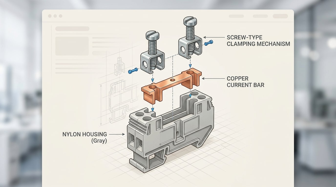
Every terminal block shares three core components:
- Housing: Typically molded from nylon (PA66) or polycarbonate, rated to UL 94 V-0 flammability standards. The housing insulates conductors from each other and from the mounting surface.
- Clamping mechanism: This is what grips the wire. Depending on the different types of terminal blocks, you’ll encounter screw clamps, spring cages, or push-in designs — each with distinct torque and vibration-resistance profiles.
- Current bar (busbar): A conductive metal strip — usually tin-plated copper or nickel-plated brass — that carries current between the connected wires. Copper alloys dominate because they balance conductivity, corrosion resistance, and cost.
How the Connection Works
Wire enters one side of the housing, contacts the current bar, and is held in place by the clamping mechanism. A second wire enters the opposite side, completing the circuit. No solder joint. No wire nut. No permanent commitment.
The real advantage? Maintenance crews can disconnect, test, and reconnect individual circuits without disturbing adjacent wiring — a critical benefit in industrial control panels where downtime costs $260,000 per hour on average, according to Aberdeen Research.
Understanding this basic structure makes it far easier to evaluate the various types of terminal blocks covered in the sections ahead, because every design variation is essentially a different answer to the same question: how should the clamp grip the wire?
Why Terminal Block Selection Matters for Safety and Performance
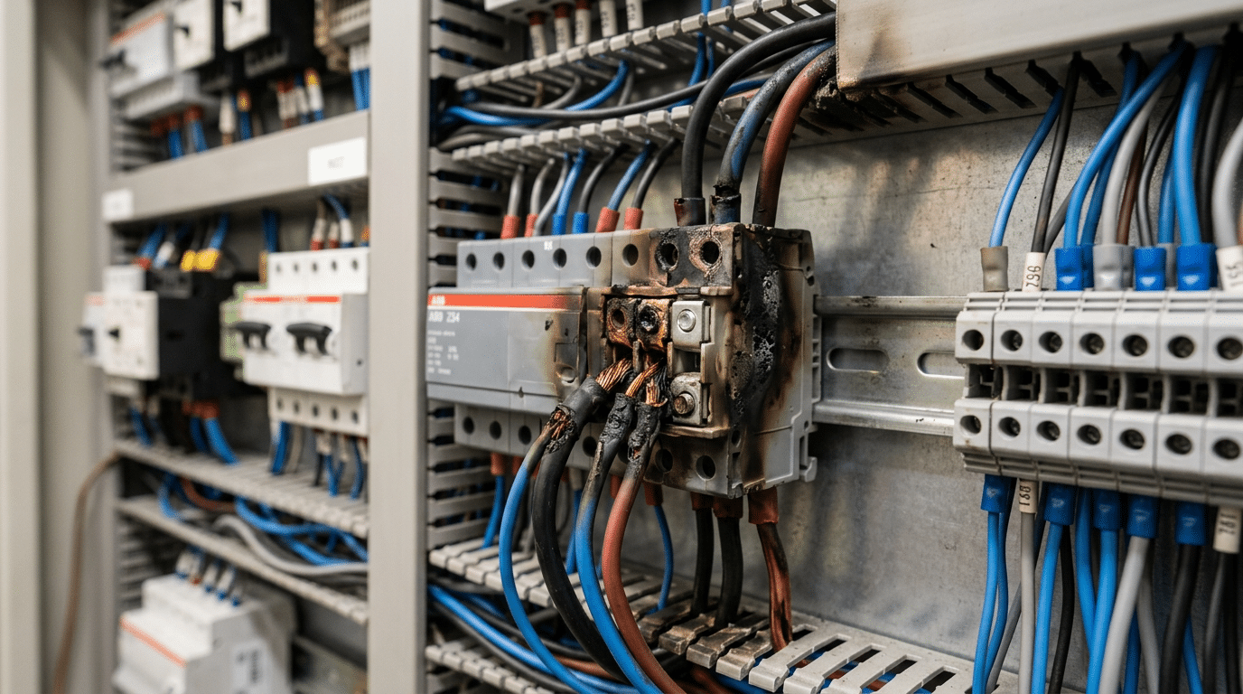
A mismatched terminal block doesn’t just underperform — it fails dangerously. Loose connections from undersized clamps generate heat, and heat causes insulation breakdown, arc faults, and in worst cases, electrical fires. According to the National Fire Protection Association (NFPA), electrical distribution equipment failures contribute to thousands of reported fires annually in the U.S. alone. Choosing among the various types of terminal blocks isn’t a casual decision; it’s a safety-critical one.
Four factors should drive every selection:
- Voltage rating: Exceeding a terminal block’s rated voltage risks dielectric breakdown between conductors. A block rated for 300V has no business in a 600V panel.
- Current capacity: Undersized terminals create resistive hot spots. A 20A-rated block carrying 30A will overheat long before a breaker trips.
- Wire gauge compatibility: Trying to force 10 AWG wire into a terminal designed for 18–14 AWG damages the clamping mechanism and produces unreliable contact.
- Environmental conditions: Vibration, moisture, temperature extremes, and chemical exposure all dictate material and design requirements. Marine and outdoor applications demand IP-rated or corrosion-resistant blocks.
Code compliance adds another layer. UL 1059 and IEC 60947-7-1 set the testing standards for terminal block performance in North America and internationally. Specifying a block without verified UL or IEC listings can trigger inspection failures and void equipment warranties. Get the type wrong, and you’re not just risking performance — you’re risking liability.
Screw Clamp Terminal Blocks
Among all types of terminal blocks, the screw clamp variant has been the workhorse of electrical connections for over a century. The mechanism is straightforward: a screw compresses a metal plate or saddle against the stripped conductor, creating a secure mechanical and electrical bond. Simple? Yes. Outdated? Far from it.
Why Engineers Still Reach for Screw Clamps
Screw clamp terminals deliver clamping forces between 2.5 Nm and 4.0 Nm depending on the terminal size, which translates to rock-solid contact resistance — often below 1 mΩ. They accommodate an impressively broad wire gauge range, typically from 26 AWG up to 300 MCM in high-power variants. That flexibility makes a single product family viable across signal-level and power distribution circuits alike.
- High clamping force — ideal for stranded, solid, and ferrule-terminated conductors
- Wide voltage and current ratings — models from Phoenix Contact and Weidmüller handle up to 1,000 V and 232 A
- Proven reliability — decades of field data in UL 1059 and IEC 60947-7-1 certified designs
The Trade-Offs You Should Know
Vibration is the enemy. In environments with sustained mechanical vibration — think mobile equipment or engine-mounted panels — screws can gradually loosen, increasing contact resistance and generating heat. That’s why NFPA 70 (NEC) Section 110.14 emphasizes proper torque values and periodic retorquing during maintenance cycles.
Installation speed is another consideration. Each connection requires a screwdriver and 5–10 seconds of torque application, which adds up fast in a 200-point control panel. For high-density applications, spring or push-in types of terminal blocks often win on labor cost alone.
Where Screw Clamp Terminals Excel
Industrial control panels, motor control centers, and power distribution boards remain their stronghold. Any application where connections are made once, inspected periodically, and rarely disturbed plays to screw clamp strengths. Brands like Allen-Bradley, WAGO, and ABB Entrelec continue to expand their screw-type DIN rail offerings precisely because demand hasn’t slowed.
Spring Cage Terminal Blocks
Forget the torque wrench. Spring cage terminal blocks use a stainless steel spring mechanism that clamps down on the conductor the moment it’s inserted, delivering consistent contact force without any manual tightening. That force doesn’t degrade over time — a critical advantage over screw-based designs where thermal cycling and vibration gradually loosen connections.
The mechanism is straightforward: a hardened spring inside the housing exerts roughly 1.2 to 2.5 N of force per mm² on the wire. You push a screwdriver into the release slot, insert the conductor, and release. The spring locks it in place permanently — or until you deliberately open it again. Weidmüller and Phoenix Contact both report that their spring cage designs maintain rated contact force across 50,000+ mating cycles.
Spring cage connections are inherently vibration-resistant because the spring continuously compensates for micro-movements that would loosen a screw terminal over months of operation.
This makes them dominant in environments where reliability under constant mechanical stress is non-negotiable. Railway signaling systems, automotive production lines, and robotic assembly cells all rely heavily on spring cage variants. Deutsche Bahn’s rolling stock specifications, for example, mandate spring-loaded connections in onboard control cabinets specifically because maintenance windows are narrow and failure costs are enormous.
Among the various types of terminal blocks used in industrial automation, spring cage models have seen the fastest adoption growth — roughly 8-12% annually according to ZVEI industry data. Their maintenance-free nature slashes lifecycle costs, particularly in installations with hundreds of termination points where re-torquing screw terminals would consume hours of labor annually.
One limitation worth acknowledging: spring cage blocks typically max out around 35 mm² conductor size, making them less suitable for high-power distribution. For signal-level and mid-range power applications up to 600V, though, they’re increasingly the default choice.
Push-In Terminal Blocks
No tool. No spring lever. Just push the wire in. Push-in terminal blocks — sometimes called direct-insertion or PUSH IN connectors — accept solid conductors and ferrule-tipped stranded wires through a simple straight insertion into the contact chamber. A precision-engineered clamping element inside grips the conductor instantly, creating a gas-tight, vibration-resistant connection in under two seconds.
That speed advantage compounds fast. In a 200-point lighting control panel, switching from screw clamp to push-in connectors can cut wiring time by 50% or more, according to Wago’s published application data. When you’re terminating hundreds of conductors across building automation or HVAC systems, those seconds per connection translate into hours saved on a project.
Where Push-In Blocks Excel
- Building automation: BACnet and KNX controllers with dense I/O counts benefit from the compact footprint — push-in blocks typically occupy 30–40% less DIN rail space than screw clamp equivalents.
- HVAC panels: Vibration from compressors and air handlers won’t loosen a push-in contact the way an under-torqued screw connection might.
- LED lighting distribution: High conductor counts (often 18–24 AWG) paired with tight enclosures make tool-free insertion almost mandatory.
Among the various types of terminal blocks, push-in designs do carry one constraint worth knowing: stranded wire without a ferrule won’t seat properly. You’ll need a crimping tool and appropriate ferrules for stranded conductors, which adds a preparation step. Phoenix Contact’s PT and Wago’s TOPJOB S series are the dominant product lines here, both rated for conductors from 28 AWG up to 10 AWG depending on the model.
Quick rule of thumb: if your panel has more than 100 termination points and uses solid or ferrule-prepped wire, push-in terminal blocks will pay for themselves in labor savings alone.
DIN Rail Terminal Blocks
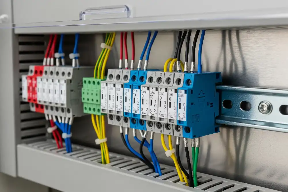
Open any industrial control panel, and you’ll see rows of them — terminal blocks snapped onto a 35mm DIN rail, organized by color, labeled by circuit. This mounting style isn’t just popular; it’s the default in industrial electrical design. The EN 60715 standard defines the 35mm top-hat rail profile, and virtually every major manufacturer — Phoenix Contact, Weidmüller, WAGO, Allen-Bradley — builds their terminal block lines around it.
Why do DIN rail terminal blocks dominate? Three reasons: modularity, density, and speed. Engineers snap blocks on or off without tools, rearrange circuits in minutes, and pack hundreds of connection points into a single enclosure. A 6mm² feed-through block typically occupies just 6.2mm of rail width — meaning you can fit over 150 connections per meter of rail.
Common DIN Rail Variants
- Feed-through (pass-through): The simplest form — wire in one side, wire out the other. Ideal for signal and power distribution in PLC cabinets.
- Multi-level: Stack two or three independent circuits vertically within a single housing, cutting rail space by 50–66%.
- Sensor terminal blocks: Purpose-built for 3- or 4-wire sensor connections, with integrated bridge contacts that distribute power and route signal lines to a controller.
- Disconnect/knife: Include a removable blade for isolating circuits during testing — covered in more detail in our specialty section.
Among all types of terminal blocks, DIN rail variants offer the widest ecosystem of accessories: end plates, partition plates, test plugs, marking strips, and jumper combs. This accessory depth is what makes them indispensable in switchgear, motor control centers, and building automation panels where hundreds of terminations must be clearly identified and easily maintained.
Pro tip: Always calculate your rail fill at 80% capacity. Thermal expansion and future circuit additions will consume that remaining 20% faster than you expect.
PCB Mount Terminal Blocks
Strip away the DIN rail, the panel, the cabinet — and put the connection point directly on the board. PCB mount terminal blocks solder onto printed circuit boards, giving designers a way to offer field-wirable connections on finished electronics without requiring end users to solder anything themselves.
Two mounting methods dominate. Through-hole (THT) terminal blocks have pins that pass through drilled holes in the PCB and are wave-soldered on the opposite side — mechanically robust and ideal for connections that experience plug/unplug cycles or vibration. Surface-mount (SMT) variants sit flat on pads and reflow with the rest of the board, saving space and supporting automated pick-and-place assembly. SMT options work well for low-current signal connections, but through-hole remains the go-to for power paths above 10A.
Pitch Sizes and Current Ratings
Pitch — the center-to-center distance between adjacent contacts — determines how compact the block can be. Common pitches include:
- 2.54 mm / 3.5 mm — signal-level connections, sensors, low-power logic boards
- 5.0 mm / 5.08 mm — the most popular for general-purpose power supplies and embedded controllers, handling 10–20A
- 7.5 mm / 7.62 mm — higher current applications up to 30A+, with greater creepage distances for safety compliance
Manufacturers like Phoenix Contact (MKDS series), Weidmüller, and Würth Elektronik publish detailed datasheets specifying UL 1059 and IEC 60947-7-1 ratings for each pitch variant. Always cross-reference the rated voltage and current against your actual board trace capacity — a 20A terminal block means nothing if the PCB trace can only carry 8A.
Among all types of terminal blocks, PCB mount versions uniquely bridge the gap between permanent board-level circuitry and removable field wiring — making them essential in power supplies, PLCs, IoT gateways, and embedded control systems.
Barrier Terminal Blocks
Big, bold, and impossible to misidentify — barrier terminal blocks are the open-style connectors you’ll find bolted directly to panels, chassis, and equipment frames. Each connection point sits between raised phenolic or nylon barriers (sometimes called “walls”), which prevent adjacent conductors from accidentally shorting against each other. The design is deliberately exposed: no housing to snap shut, no rail to mount on. Just screws, lugs, and clear sightlines.
That visibility is the whole point. Technicians can inspect torque, verify wire gauge, and spot corrosion without disassembling anything. It’s why barrier strips remain a staple in power distribution panels, professional audio amplifiers, and legacy industrial control systems where equipment may run for 20–30 years between major overhauls.
Where Barrier Strips Excel
- Power distribution: Rated commonly from 15 A up to 75 A per pole (some heavy-duty models reach 150 A), making them suitable for branch circuit breakouts and transformer secondary connections.
- Pro audio and AV racks: Speaker-level outputs on Crown, QSC, and similar commercial amplifiers frequently use barrier-style terminals for quick field wiring.
- Legacy industrial retrofits: Older motor control centers and relay panels were built around barrier blocks — replacing them with modern types of terminal blocks often isn’t cost-justified when the existing hardware still meets UL 1059 or CSA C22.2 No. 158 requirements.
One trade-off: because the connections are exposed, barrier terminal blocks aren’t ideal for environments with conductive dust, moisture, or vibration-prone installations. If your panel lives in a clean, accessible location and you need high current capacity with zero guesswork during maintenance, barrier strips remain one of the most practical types of terminal blocks available.
Specialty Terminal Blocks — Fused, Ground, and Disconnect Types
Some connections need more than a simple wire-to-wire junction. Three purpose-built types of terminal blocks — fused, ground, and disconnect — solve specific problems that standard blocks can’t address without external components.
Fused Terminal Blocks
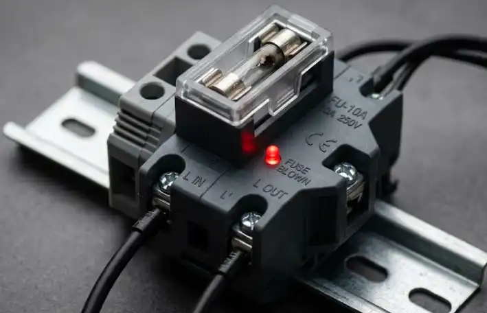
A fused terminal block embeds a cartridge fuse holder directly into the connection point, providing inline overcurrent protection at the individual circuit level. Typical ratings range from 0.5A to 15A with voltage support up to 600V. When a fault occurs, only the affected circuit loses power — the rest of your panel stays live. Weidmüller and Phoenix Contact both offer fused blocks with LED blown-fuse indicators, cutting diagnostic time from minutes to seconds.
Ground Terminal Blocks
Ground blocks create a dedicated, low-impedance earth path by making direct metal-to-metal contact with the DIN rail. That rail continuity eliminates the need for separate grounding busbars in many panel designs. They’re typically yellow-green per IEC 60947-7-1 color coding, making them instantly identifiable during inspection.
Disconnect (Knife) Terminal Blocks
Need to isolate a circuit for testing without pulling wires? Disconnect blocks feature a pivoting knife blade or removable link that interrupts the circuit in place. Technicians can insert a multimeter across the open contacts to measure loop current — a critical capability in 4–20mA instrumentation circuits. No rewiring, no downtime beyond the test itself.
All three specialty types of terminal blocks mount on standard 35mm DIN rail alongside conventional blocks, so integrating them into existing panels requires zero layout changes.
How to Choose the Right Terminal Block for Your Application
Start with three non-negotiable specs: wire gauge range, rated current, and rated voltage. A 24 AWG signal wire and a 4 AWG power feeder demand completely different blocks. Check the manufacturer’s datasheet — never assume a block handles your conductor size just because the wire physically fits.
Next, match the connection method to your workflow. High-volume production lines favor push-in or spring cage blocks for speed. Maintenance-heavy environments where technicians retorque connections benefit from screw clamp designs. Your team’s skill level and available tooling matter more than most engineers admit.
Environment kills connections. Vibration-prone machinery rules out loose screw terminals — spring cage or push-in types resist vibration fatigue far better. Outdoor or washdown areas require IP-rated housings and corrosion-resistant materials. Always verify UL and IEC certifications (UL 1059, IEC 60947-7-1) for your target market; uncertified blocks can void insurance and fail inspection.
Quick-Reference Comparison of All 10 Types of Terminal Blocks
| Type | Connection Method | Typical Current | Best-Fit Use Case |
|---|---|---|---|
| Screw Clamp | Screw | Up to 300 A | General industrial wiring |
| Spring Cage | Spring lever | Up to 232 A | Vibration-prone machinery |
| Push-In | Direct insertion | Up to 76 A | High-volume panel assembly |
| DIN Rail Mount | Varies | Up to 300 A | Control panels, PLCs |
| PCB Mount | Solder/plug | Up to 76 A | Board-level power & signal |
| Barrier | Screw + barrier | Up to 600 A | High-power open panels |
| Fused | Varies | Circuit-dependent | Branch circuit protection |
| Ground | Screw/spring | Per conductor | Safety grounding, PE buses |
| Disconnect | Knife/plug | Up to 20 A | Test points, signal isolation |
| Pluggable | Plug + header | Up to 76 A | Field-serviceable modules |
Use this table as a starting filter, then narrow by your specific voltage class, approval requirements, and mounting constraints. Choosing among the various types of terminal blocks becomes straightforward once you treat it as a checklist — not a guess.
Frequently Asked Questions About Terminal Blocks
What’s the difference between a terminal block and a terminal strip?
A terminal strip is simply a row of terminal blocks mounted together on a single housing or rail. Think of it this way: a terminal block is the individual connection point, while a terminal strip is the assembly. Most manufacturers — Phoenix Contact, Weidmüller, Wago — use the terms interchangeably in catalogs, but technically the strip refers to the grouped unit.
Can terminal blocks be reused?
Yes — most types of terminal blocks are designed for repeated use. Spring cage and push-in variants handle hundreds of insertion cycles without degradation. Screw clamp models also tolerate re-termination, though you should inspect the clamping plate for wear marks after 10+ reconnections. Replace any block showing deformed threads or cracked housing.
What’s the maximum wire size supported?
Standard DIN rail blocks top out around 240 mm² (roughly 500 MCM). Barrier-style blocks for power distribution can accommodate conductors up to 350 MCM. For most control panel work, 2.5 mm² to 16 mm² covers the vast majority of applications.
Are terminal blocks rated for outdoor use?
Not by default. Indoor-rated blocks typically carry a UL 94 V-0 flammability rating but lack UV resistance or IP-rated sealing. For outdoor installations, look for blocks housed inside NEMA 4X or IP66 enclosures, or choose models with UV-stabilized polyamide housings specifically marketed for harsh environments.
How tight should screw-type terminals be?
Over-torquing damages conductors; under-torquing causes hot spots. Always follow the manufacturer’s specified torque value — typically 0.5–0.8 Nm for blocks rated up to 4 mm², and 2.5–3.5 Nm for larger power blocks. A calibrated torque screwdriver isn’t optional here. The NEC (Article 110.14) requires connections be made with listed torque tools when values are specified.
Choosing With Confidence — Your Next Steps
You’ve now seen ten distinct types of terminal blocks — each engineered for a specific set of conditions. Here’s the rapid-fire recap:
- Screw clamp — reliable, high-vibration tolerance, ideal for heavy industrial wiring.
- Spring cage — maintenance-free clamping, perfect for automation panels.
- Push-in — fastest installation, great for high-density control cabinets.
- DIN rail mount — the backbone of organized panel layouts.
- PCB mount — board-level connections for power supplies and embedded systems.
- Barrier — high-current, open-chassis applications up to 600V.
- Fused — inline overcurrent protection without extra components.
- Ground — direct bonding to DIN rail for safety compliance.
- Disconnect — test and isolate circuits without rewiring.
- Sensor/actuator — multi-level designs that consolidate field device wiring.
Match your wire gauge, voltage rating, and environmental demands to the right category first — then narrow by brand and series. That single step eliminates 80% of selection errors.
For mission-critical installations — think medical equipment, rail signaling, or explosive atmospheres — don’t rely on general guidance alone. Pull the manufacturer’s datasheet, verify UL/IEC certifications against your local code, and consult a licensed electrical engineer before finalizing your bill of materials. Brands like Phoenix Contact, Weidmüller, and Wago publish detailed selection guides that cross-reference application types with specific product families.
The right terminal block isn’t the most expensive one — it’s the one whose ratings, mounting style, and connection method align precisely with your project’s real-world conditions.
See also
How to Pick the Ideal Terminal Block for Your Project
What You Should Know About Terminal Blocks and Their Other Names
Quick Guide to Common Terminal Blocks in Industrial Automation
How many types of wiring terminals are there?
Wholesale PT 2.5 Spring Din Rail Terminal Block

Discover more from SENTOP Electrical Co., Ltd
Subscribe to get the latest posts sent to your email.
