
How to Test a Terminal Block With a Multimeter: 3 Diagnostic Checks
A multimeter can answer three different questions: is a de-energized path continuous, is the expected voltage present, and does a defined connection develop abnormal voltage drop under load? The functions, circuit state, hazards, and interpretation are different for each check.
Testing inside industrial equipment can expose shock and arc-flash hazards. Energized measurements belong to qualified persons following the facility's approved electrical-safety program. If that is not you, stop and engage a qualified electrical worker.

Pick the question before the meter function
“Test the terminal block” is not one measurement. First decide whether you are proving an electrically safe work condition, finding an open path, checking supply voltage, or evaluating a connection while it carries current.
Need to prove it is safe to touch?
Use the site's energy-isolation and absence-of-voltage procedure. One zero reading is not proof, and continuity mode is not an absence-of-voltage test.
Safety gate firstNeed to find an open path?
After isolation, lockout/tagout, verification, discharge, and sufficient circuit separation, use continuity or resistance to screen the defined path.
De-energized checkNeed evidence under load?
A qualified person may use voltage or direct voltage-drop measurements when energized diagnostics are justified and permitted by the work plan.
Qualified persons onlyThree checks, three different answers
The safest way to learn how to test a terminal block with a multimeter is to separate the diagnostic questions. Continuity screens for a path with power removed. Voltage checks electrical potential between defined reference points. Voltage drop evaluates a defined connection while known current is flowing.
These are not mandatory consecutive steps. A machine that is already de-energized may need only a drawing review, visual inspection, and isolated continuity check. A live process symptom may justify a voltage measurement by a qualified person without any prior ohms test. A loaded connection may require a controlled voltage-drop comparison, but only when the electrical-safety program permits the energized task.
| Diagnostic question | Meter function | Required circuit state | Useful evidence | Critical limit |
|---|---|---|---|---|
| Is there an electrical path? | Continuity or Ω | De-energized | Open-path screening after the path is isolated enough to avoid parallel routes. | A beep is meter-specific; it does not certify terminal contact resistance. |
| Is the intended potential present? | V AC or V DC | Energized task | Voltage at schematic-defined input, output, line, neutral, common, or polarity points. | Only a qualified person may perform the energized measurement under an approved procedure. |
| What does one connection drop under load? | V AC / mV AC or V DC / mV DC as applicable | Loaded and stable | Potential directly across one defined interface, paired with the actual load current. | There is no universal millivolt pass/fail number for every terminal. |
Use continuity or resistance only on an isolated, de-energized, discharged path. Use the correct AC or DC voltage function for energized measurements. Measure voltage drop directly across a defined connection under a known stable load, then compare with manufacturer criteria or a controlled same-product baseline—not an internet rule of thumb.
Path
Does the drawing say these two test points should be connected in the current device state?
Potential
Which two references define the expected reading: line-to-line, line-to-neutral, DC positive-to-negative, or a signal common?
Load behavior
Is the symptom current-dependent, and can the exact connection be compared under the same current, temperature, and measurement geometry?
Pass the electrical-safety gate
A breaker handle, HMI status, indicator lamp, or single meter reading does not establish an electrically safe work condition. Identify every energy source, understand the grounding arrangement, control stored energy, and follow the applicable site procedure before exposing or touching a terminal.
De-energize whenever possible
Under OSHA 1910.333, parts that have been de-energized but not locked or tagged are treated as energized. Energized testing is restricted to qualified persons, and the exception for energized work must be established by the task—not by convenience.
-
Define the equipment and every source
Use the current schematic, terminal schedule, device state, nominal AC/DC system, grounding method, and test-point identifiers. Include control power, backfeed, UPS or battery supplies, capacitors, remote I/O, generated power, and induced voltage where relevant.
-
Establish the work condition
Interrupt load with the correct rated device, isolate all sources, apply lockout/tagout as required, release or restrain stored energy, and use barriers or boundaries defined by the site program. Do not use a fuse or terminal lug as a load-break device unless it is specifically rated for that purpose.
-
Inspect and configure the complete test system
Check the meter, leads, probes, clips, adapters, insulation, finger guards, connectors, and manufacturer-specified fuses. Put the black lead in COM and the red lead in the voltage/ohms input. Never place a voltage source across a current input.
-
Verify absence of voltage correctly
A qualified person follows the applicable live-dead-live process: prove the tester on a known source of the applicable AC or DC type, test every relevant conductor combination at the point of work, and prove the tester again. Follow the system design for phase-to-phase, phase-to-ground, positive-to-negative, and polarity-to-ground checks.
-
Only then change the circuit or use Ω mode
After the safe work condition is established, discharge capacitive energy and isolate the measurement path enough to prevent parallel circuits from creating a false continuity result. Keep the lockout/tagout in place during corrective work.

Select CAT and voltage ratings from the actual measurement location
IEC 61010 measurement categories describe the transient environment and available energy at the measurement point. They are not a generic “arc-flash protection” label. Select the category and working-voltage rating for the actual circuit, and treat the lowest-rated meter, lead, probe, clip, or adapter as the rating of the complete assembly.
| Category | Typical location concept | Terminal-block implication |
|---|---|---|
| CAT II | Load-side points connected to receptacles and similar utilization circuits. | Do not assume this rating is adequate inside distribution equipment merely because the nominal voltage fits. |
| CAT III | Fixed distribution wiring, switchgear, feeders, and distribution panels. | Common in industrial panel work, but the required working-voltage rating still depends on the actual circuit. |
| CAT IV | Origin of installation, utility service, meters, and outdoor source-side conductors. | Service-side terminal measurements may require this higher category; verify the installation boundary. |
- Correct AC or DC function and range for the intended reading
- COM and voltage/ohms jacks confirmed before approaching the circuit
- Meter, leads, probes, caps, clips, and adapters rated as one system
- Probe tip exposure and finger guards suitable for the CAT environment
- Risk-assessment-based shock and arc-flash PPE—not a universal glove rule
- Approved test points and enough clearance to prevent an accidental bridge
They can be bonded at specific points yet serve different functions and show different potentials during faults. Select every reference point from the schematic and the system grounding arrangement.
Use continuity to screen an isolated, de-energized path
Continuity mode is useful for finding an open conductor path, a removed or blown fuse, a disconnect state, or a gross wiring error. It is not a precision contact-resistance test, and it must never be used on an energized circuit.
-
Define the exact path on the drawing
Mark the two endpoints and every component between them. A terminal may include a disconnect knife, fuse, diode, resistor, bridge, LED, or test socket, so the expected result depends on device design and operating position.
-
Isolate, verify, discharge, and separate the path
Follow the safety gate above. Disconnect or otherwise isolate the relevant branch as the approved procedure requires. Parallel loads, coils, indicator circuits, and bonded commons can make the meter beep even when the intended terminal path is open.
-
Check the meter and lead contribution
Select continuity or resistance as the meter manual specifies, then touch the probes together. Record the lead reading or use the instrument's relative-zero function for a rough comparison. A typical two-wire lead contribution may be comparable with the change you are trying to see.
-
Probe designated test points without disturbing the conductor
Place the probes across the defined input and output points or manufacturer-provided test sockets. Do not scrape plating, force a probe into the clamping space, or wiggle a conductor to “make” a diagnosis.
-
Interpret the circuit, not just the display
“OL” can mean a true open, a removed fuse, a device in the open state, a wrong point, or a failed lead. A beep means only that the measured path is below that meter's continuity threshold. Confirm the state, drawing, lead check, and isolation before deciding what failed.
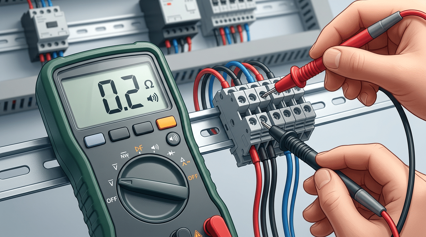
A path exists in this test state
When the drawing, isolation, device position, and probe points are correct, continuity supports that current can flow through some available path.
The joint is healthy under load
The beeper threshold is model-specific and may be far above terminal contact resistance. Parallel paths and lead resistance further limit the conclusion.
Why an ordinary DMM cannot certify contact resistance
Many terminal contacts are designed to add only a very small resistance. With a conventional two-wire ohms measurement, the reading includes both leads, probe-to-test-point interfaces, conductor segments, and the terminal itself. The meter's resolution and test current may be unsuitable for separating those contributions.
If the maintenance or quality plan requires a quantitative low-resistance result, use the terminal manufacturer's test method and acceptance limit. A suitable four-wire Kelvin instrument separates the current and sense paths, but the correct test current, connection points, temperature correction, and pass criteria still come from the product or engineering specification.
After safe isolation and absence-of-voltage verification, test the removed fuse only when removal is permitted, then test the terminal path in the device's documented state. The line side may remain energized if the wrong source was isolated, and an ordinary fuse holder must not be used to interrupt load unless it is rated for that operation.
Measure voltage only with the right reference and authority
Voltage testing can show whether the expected electrical potential reaches a terminal in a defined operating state. Because it is an energized measurement, it is performed only by a qualified person when the task is justified, planned, and controlled under the site's electrical-safety program.
This guide explains the diagnostic logic; it does not authorize energized work. The worker must understand the equipment, shock and arc-flash exposure, boundaries, PPE, meter limitations, safe probe placement, and emergency response before the enclosure is opened.
-
Write the expected value and reference pair
Use the drawing and device data to state the expected AC or DC voltage and operating tolerance at each test point. Specify line-to-line, line-to-neutral, line-to-ground, positive-to-negative, polarity-to-ground, or signal-to-common as applicable.
-
Select the function and complete test assembly
Choose V AC or V DC, confirm the input jacks, and verify the meter can measure the waveform. Non-sinusoidal loads, switching supplies, and variable-frequency drives may require true-RMS capability, adequate bandwidth, a low-pass function, or a specialized instrument.
-
Prove and position the tester under the approved plan
Use the site's known-source verification method, approved test points, probe accessories, barriers, approach boundaries, and PPE. Keep probe exposure controlled and do not improvise a back-probe path that can bridge adjacent terminals.
-
Measure the defined pairs in a controlled sequence
Record the equipment state, load state, reference pair, meter mode, and result. Comparing an input and output reading is meaningful only when both are referenced consistently and the operating state has not changed between readings.
-
Return the equipment to a safe condition
Remove probes and restore guards according to the procedure, then verify the tester again when the absence-of-voltage or site process requires it. If any connection will be touched, tightened, cleaned, or replaced, de-energize, lock/tag, and verify before corrective work.
| Observed pattern | What it may support | What to check before blaming the terminal |
|---|---|---|
| Expected input; no expected output | An open device, conductor, fuse, disconnect point, or terminal path between the two points. | Device state, fuse status, bridge configuration, control interlocks, drawing revision, and reference point. |
| Both readings low | A source, upstream distribution, control, or load-related problem. | Source regulation, upstream drop, load current, conductor length, simultaneous measurements, and equipment tolerance. |
| Open-circuit voltage normal; voltage collapses with load | Excess source impedance or a high-resistance series connection somewhere in the path. | Measure controlled segments, verify load current, and compare upstream and downstream points without changing state. |
| Unexpected polarity or AC/DC behavior | A reversed reference, wiring error, floating circuit, induced voltage, or unsuitable meter mode. | Drawing, grounding arrangement, meter function, low-impedance test method where approved, and waveform requirements. |
Measure voltage drop across one defined connection
A high-resistance joint can pass a continuity check and show normal open-circuit voltage, then fail when current flows. Direct voltage-drop testing can reveal that behavior—but only when the connection boundary, load current, AC/DC mode, waveform, and comparison basis are controlled.
The reading changes with current
If a defined connection had 10 milliohms of resistance and carried a stable 5 amperes, the calculated drop would be 0.05 volts. At a different current, the drop changes. That is why a universal millivolt threshold cannot qualify every terminal block.
-
Justify and plan the energized diagnostic task
Confirm that the result is needed and that the qualified worker, risk assessment, PPE, boundaries, instrument, probes, and test points satisfy the facility procedure. Whenever possible, use permanently designed test points or de-energized alternatives.
-
Define one measurement boundary
Place the two measurement points directly on opposite sides of the same intended interface. A reading that spans a conductor, fuse, two clamps, and a bridge combines all of those elements and cannot identify which one is responsible.
-
Stabilize and record load current
Document current, operating state, conductor size, ambient or connection temperature, meter mode, and measurement points. AC circuits require the applicable AC function; DC circuits require the applicable DC function.
-
Compare like with like
Evaluate the result against the exact terminal manufacturer's method or a controlled baseline from the same product, conductor, current, temperature, and probe geometry. Neighboring positions are useful only when those conditions are comparable.
-
Stop, isolate, and investigate abnormal evidence
Do not tighten a live screw or disturb a conductor to see whether the reading changes. If the result departs from the approved criterion or stable baseline, place the equipment in a safe state and inspect the full connection system.
Some increase in drop is expected from Ohm's law. Temperature may also change resistance, so record both.
A repeatable upward trend can support deterioration, but confirm identical points and instrument conditions.
Investigate the connection, conductor preparation, device, and environment after safe isolation.
A single online threshold ignores current, terminal design, conductor size, temperature, number of interfaces, waveform, probe location, and instrument accuracy. Use the exact product data, engineered limit, or controlled baseline.
Turn readings into a defensible fault hypothesis
A meter result narrows the search; it rarely proves one root cause by itself. Combine electrical readings with the schematic, load condition, thermal or visual evidence, connection history, conductor preparation, and the terminal manufacturer's instructions.
| Evidence pattern | Plausible explanations | Safe next action |
|---|---|---|
| No continuity after correct isolation | Open conductor, blown or removed fuse, open disconnect terminal, missing bridge, wrong test points, failed contact, or failed lead. | Recheck meter and drawing; divide the de-energized path into documented segments before replacing parts. |
| Continuity beep, but the load still fails | Parallel path, meter beeper threshold, intermittent contact, insufficient contact area, upstream issue, or a fault that appears only at load. | Improve isolation; use an engineered low-resistance method or qualified loaded diagnostic if justified. |
| Correct voltage upstream, absent downstream | Open protective device, disconnect point, conductor, bridge, terminal path, or incorrect operating state. | Map each series element, then isolate before testing or correcting the suspected component. |
| Voltage is normal with no load, then collapses | High source impedance, an undersized or damaged conductor, a weak supply, or a resistive connection anywhere upstream. | Record load current and segment the voltage drop with controlled measurement points. |
| One connection has a higher controlled drop | Incorrect conductor preparation, reduced clamping force, contamination, corrosion, damaged strands, thermal damage, or a failing fuse contact. | Stop and safely isolate; inspect and disposition the complete terminal–conductor system to the exact product instructions. |
| Reading changes with vibration or temperature | Intermittent connection, conductor fatigue, loose mounting, cracked housing, relaxation, or a moving parallel path. | Do not wiggle live conductors. Remove the equipment from service when risk warrants and investigate de-energized. |
| Visual heat, carbonization, melting, or tracking | Past overheating, contamination, insulation breakdown, incorrect spacing, excessive current, or an upstream protection problem. | Do not rely on a “good” meter reading. Isolate and replace damaged components as required, then investigate the initiating cause. |
Four things a standard handheld DMM does not certify
Terminal contact resistance
Two-wire lead and probe resistance can dominate the reading. Use the specified four-wire method when quantitative milliohm data is required.
Insulation integrity
A DMM ohms range is not an insulation-resistance test. Use an appropriate insulation tester and isolate sensitive electronics under a qualified procedure.
Correct clamping force
Electrical behavior cannot prove that a screw, spring, or push-in contact was assembled to the exact product requirement.
Remaining service life
A snapshot cannot rule out fatigue, hidden plating damage, thermal history, or an intermittent fault that was absent during the test.
Escalate instead of continuing when:
- the source, grounding arrangement, or terminal function cannot be identified from current documentation;
- the meter, leads, probes, CAT rating, voltage rating, or fuse condition is uncertain;
- energized parts are exposed and the worker is not qualified or the energized task is not approved;
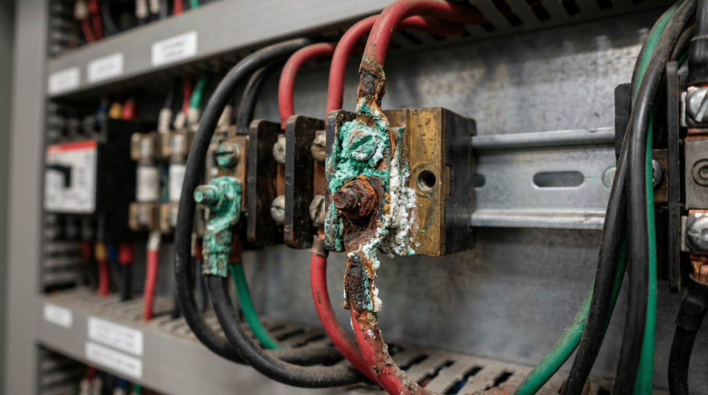
- the enclosure shows arcing, carbonization, melted insulation, severe corrosion, water ingress, or unstable behavior; or
- the proposed test would require touching, moving, tightening, cleaning, or removing a component while energized.
For deeper root-cause work, use SENTOP's terminal block failure analysis guide. If the evidence points to a connection problem, follow the separate safe loose-connection workflow only after the equipment is de-energized, locked/tagged, and verified.
Build a test record that another technician can reproduce
A number without context is difficult to defend. A useful terminal-block test record identifies the circuit, safe-work state, meter configuration, exact test points, load, environment, baseline, and resulting action.
| Record field | What to capture | Why it matters |
|---|---|---|
| Asset and point | Panel, circuit, terminal strip, position, wire marker, drawing revision, and terminal model. | Prevents comparison of different devices or outdated wiring states. |
| Safety state | Isolation points, lockout/tagout reference, absence-of-voltage verification, barriers, or energized-work authorization. | Shows which work condition applied and whether the measurement was permitted. |
| Instrument system | Meter model, function, range, lead/probe type, rating, lead-zero value, and calibration status where required. | Explains resolution, limits, and whether later readings are comparable. |
| Electrical condition | AC/DC waveform, nominal value, exact reference pair, device state, load current, and upstream condition. | Connects the result to the real operating point. |
| Environment and evidence | Temperature, vibration, moisture, contamination, discoloration, conductor condition, and controlled photos. | Supports correlation without assigning the wrong cause to one reading. |
| Criterion and action | OEM limit or approved baseline, deviation, disposition, parts replaced, exact work instruction, and retest result. | Turns troubleshooting into a traceable maintenance decision. |
Use a controlled correction loop
Confirm
Repeat the measurement with the same points and state; verify the instrument and drawing.
Isolate
Stop the equipment as risk requires, isolate every source, lock/tag, verify, and discharge.
Disposition
Inspect the terminal, conductor, fuse, bridge, mounting, and environment to the exact product instructions.
Verify
Perform the authorized post-work checks, restore guards, remove LOTO correctly, and document the baseline.
Some terminal technologies are maintenance-free; others have precise torque, conductor, tool, and rework instructions. Over-tightening can damage the clamping system or conductor. Heat damage, carbonization, cracked insulation, severe pitting, lost spring force, or uncertain integrity can require replacement rather than cosmetic cleaning or repeated tightening.
Send the circuit facts, and SENTOP can help shortlist the terminal system
If testing points to a replacement or redesign, share the application data rather than only a photo. SENTOP can help compare screw, spring, push-in, feed-through, fuse, disconnect, and multi-level terminal options for the documented operating envelope.
Include these six inputs
- Exact terminal model and connection technology
- Conductor material, type, cross-section, and preparation
- Nominal AC/DC voltage and continuous or peak current
- Schematic reference and available test-point arrangement
- Temperature, vibration, moisture, chemicals, and enclosure
- Required approvals, quantity, destination, and service target
From test evidence to the right next decision
9 Terminal Block Faults
Match symptoms with plausible causes and safe corrective routes without over-reading one meter result.
Terminal Block Wiring Guide
Review conductor preparation, wiring sequence, marking, and verification before re-termination.
Read Terminal Specifications
Translate ratings, conductor ranges, connection data, and approvals into a defensible shortlist.
Maintenance Checklist
Build inspection intervals from risk, environment, condition, manufacturer guidance, and equipment criticality.
Testing terminal blocks with a multimeter FAQ
What multimeter setting should I use to test a terminal block?
Use continuity or resistance only on a de-energized, isolated, discharged path. A qualified person uses the appropriate V AC or V DC function for energized voltage, and the applicable AC or DC voltage range across a defined loaded connection for voltage drop.
Can I test a terminal block without disconnecting the wires?
Voltage and voltage-drop measurements may be possible without disconnecting conductors, but they are energized tasks for qualified persons under an approved procedure. Continuity or resistance usually requires safe isolation and enough circuit separation to eliminate misleading parallel paths.
What resistance reading means a terminal block is good?
There is no universal handheld-DMM resistance value that proves a terminal is good. Lead and probe resistance can dominate a two-wire reading, and the beeper threshold is meter-specific; use the manufacturer's criterion and a suitable four-wire low-resistance method when quantitative contact-resistance testing is required.
How do I test a fuse terminal block?
First isolate all sources, apply lockout/tagout as required, verify absence of voltage, and confirm the device permits fuse removal. Test the fuse and the terminal path separately in their documented states; never use an ordinary fuse holder to interrupt load unless it is specifically load-break rated.
Why does the meter beep even though the circuit still fails under load?
A continuity beep only means the measured resistance is below that meter's threshold. A parallel path, intermittent joint, source problem, or resistance too small for the beeper to distinguish can still make the circuit fail when current flows.
Should I retorque or replace a suspect terminal block?
De-energize, lock/tag, and verify before any physical correction, then follow the exact model's instructions. Retorque only when specified; replace or escalate when there is heat damage, carbonization, cracking, severe pitting, damaged conductors, lost clamping integrity, or an uncertain approval-compliant repair.
Standards and authoritative sources
This guide uses official safety requirements, current IEC product-safety standards, and primary manufacturer measurement guidance. Apply the edition adopted by the authority having jurisdiction and the site's own electrical-safety program.
- OSHA 29 CFR 1910.333—Selection and use of work practices
- OSHA 29 CFR 1910.334—Use of equipment, including test instruments
- OSHA 29 CFR 1910.335—Safeguards for personnel protection
- NFPA 70E—Standard for Electrical Safety in the Workplace, 2027 edition
- IEC 61010-2-033:2023—Hand-held multimeters for mains voltage
- IEC 61010-031:2022—Hand-held probe assemblies and accessories
- Fluke—Absence-of-voltage testing and live-dead-live verification
- Fluke—How to measure resistance safely with a digital multimeter
- Keysight—Two-wire and four-wire resistance measurements
- Phoenix Contact—Electrical product tests for terminal blocks

