
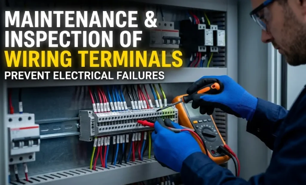
Loose or degraded terminal block connections account for roughly 30% of all electrical failures in industrial control panels, according to data referenced in NFPA 70B recommended maintenance practices. A structured terminal block maintenance checklist is the single most effective tool for catching these failures before they escalate into unplanned downtime, arc flash incidents, or costly equipment damage. This guide walks you through 15 essential inspection steps — from pre-work safety lockouts to torque verification, thermal scanning, and compliance documentation — so you can build a repeatable maintenance routine that actually holds up under audit.
What a Terminal Block Maintenance Checklist Covers and Why It Matters
Loose, corroded, or overtorqued terminal connections cause roughly 30% of electrical equipment failures in industrial settings, according to data referenced in NFPA 70B — Recommended Practice for Electrical Equipment Maintenance. A structured terminal block maintenance checklist exists to catch these failures before they escalate into arc faults, unplanned production shutdowns, or panel fires.
So what does a thorough checklist actually cover? Here are the 15 essential inspection steps at a glance:
- Lockout/tagout verification and pre-inspection safety
- Visual scan for discoloration, melting, or cracked housings
- Check for arcing marks and carbon tracking on insulation
- Torque verification against manufacturer specs
- Re-torquing loose connections with a calibrated torque driver
- Infrared thermography to detect hot spots under load
- Wire-pull test on ferrule and spring-cage terminations
- Corrosion and contamination cleaning
- Insulation resistance measurement (megger test)
- Labeling and marking legibility check
- DIN rail seating and mechanical integrity inspection
- Environmental seal and IP rating confirmation
- NEC and NFPA 70B compliance review
- Documentation and photo logging of findings
- Scheduling the next maintenance interval
Pro tip: Don’t treat this as a one-time audit. The real value of a terminal block maintenance checklist comes from repeatable, documented cycles — quarterly at minimum for high-vibration environments, annually for climate-controlled panels.
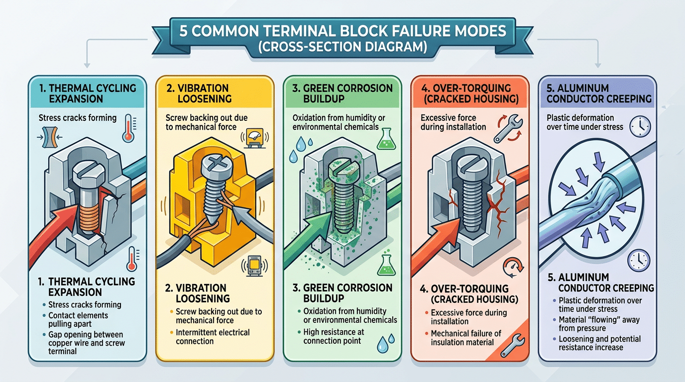
Why Terminal Blocks Fail — Common Causes of Connection Degradation
Terminal blocks don’t fail randomly. They fail predictably — and every item on a solid terminal block maintenance checklist traces back to one of five root causes.
Thermal Cycling and Conductor Creep
Repeated heating and cooling cycles cause conductors to expand and contract, gradually loosening the clamping force. Aluminum conductors are especially vulnerable: they exhibit conductor creep — a slow, permanent deformation under sustained mechanical stress — at rates significantly higher than copper. According to NFPA 70B, loose connections account for a significant share of electrical failures, with thermal cycling identified as a primary contributor. A connection that measured perfect torque at commissioning can lose 20–40% of its clamping force within the first year of operation.
Vibration, Corrosion, and Over-Torquing
- Vibration-induced loosening: Equipment mounted near motors, compressors, or HVAC units experiences constant micro-vibrations that back out screws over months. Spring-cage terminals resist this far better than screw-type designs.
- Environmental corrosion: Humidity, chemical vapors, and salt air attack plating and conductor surfaces, creating resistive oxide layers that generate heat under load.
- Over-torquing: Technicians who “crank it tight for safety” actually deform the conductor or crack the terminal housing, creating a hidden failure point that won’t show symptoms until catastrophic overheating occurs.
Understanding these mechanisms is what separates a meaningful terminal block maintenance checklist from a checkbox exercise. Each inspection step in the sections ahead directly targets one or more of these degradation pathways.
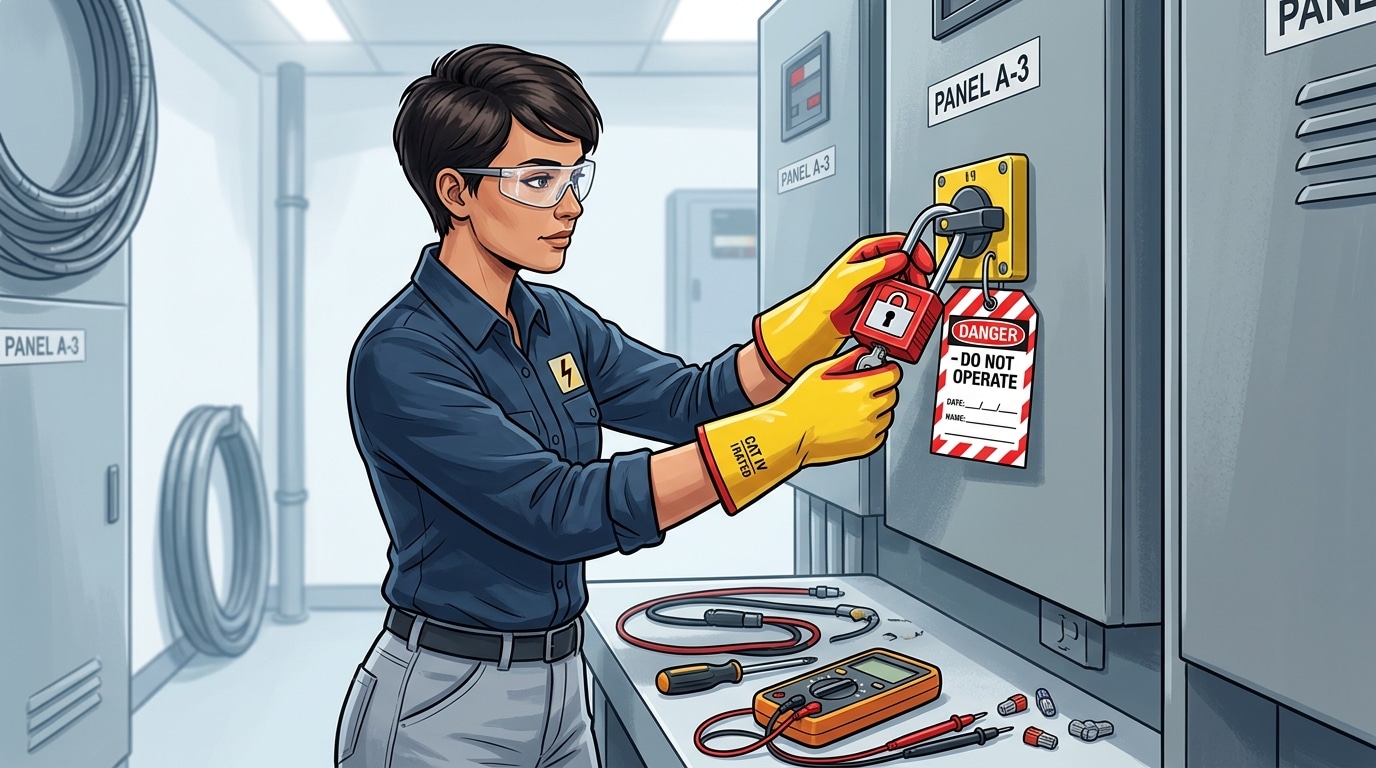
Pre-Inspection Safety and Lockout Tagout Procedures
Every terminal block maintenance checklist must begin here — before you pick up a torque wrench or infrared camera. According to Bureau of Labor Statistics data, electrical contact caused 126 workplace fatalities in 2022 alone. Skipping lockout tagout (LOTO) is the fastest way to become a statistic.
Establish an Electrically Safe Work Condition
Follow NFPA 70E Article 120 precisely. The sequence matters:
- Identify all energy sources feeding the terminal block panel — including backfed circuits that single-line diagrams often miss.
- Notify affected personnel, then open the disconnecting means.
- Apply your personal lockout device and tag at each isolation point.
- Verify absence of voltage using a CAT III or CAT IV rated multimeter — test on a known live source first, then on the circuit, then back on the known source. This “live-dead-live” method catches failed meters before they give you a false zero reading.
Pro tip: A non-contact voltage tester is a screening tool, not a verification device. Never rely on it as your sole confirmation of de-energization.
PPE and Arc Flash Boundaries
Even after LOTO, wear voltage-rated gloves appropriate to the system voltage and safety glasses with side shields. Check the arc flash label on the panel — it dictates the incident energy level and required PPE category. Missing or illegible labels require an arc flash study before any terminal block inspection proceeds.
Visual Inspection Checklist for Terminal Block Connections
Your eyes catch problems faster than any meter — if you know what to look for. A structured visual inspection is the first active step in any terminal block maintenance checklist, and it flags roughly 67% of developing faults before they escalate to failures, according to NFPA 70B recommended practices.
Work through these visual checks systematically, one terminal at a time:
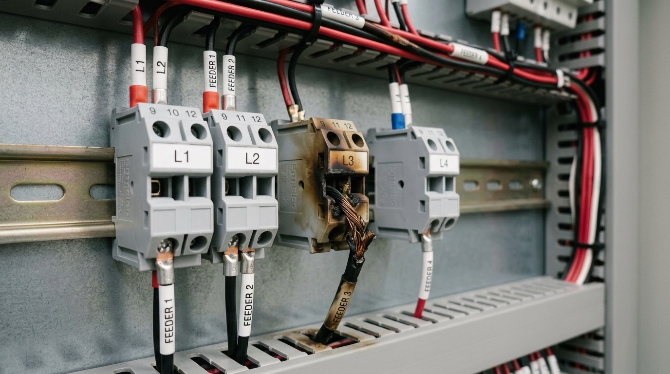
- Discoloration or browning on the housing — indicates sustained overheating, often from a loose connection or overcurrent condition.
- Melted or deformed plastic — the terminal has exceeded its rated temperature. Replace immediately; the insulation’s dielectric strength is compromised.
- Cracked housings — vibration fatigue or overtorquing during installation. Hairline cracks invite moisture ingress and tracking (surface arcing along contaminated insulation).
- Backed-out conductors — gently tug each wire. If it moves, the connection has failed mechanically.
- Carbon deposits or pitting — classic arcing signatures. Even small arc marks mean the contact resistance spiked high enough to ionize air.
- Label legibility — faded or missing wire markers slow troubleshooting and increase the risk of reconnection errors.
Pro tip: photograph every anomaly with a reference scale before corrective action. This builds the documentation trail your terminal block maintenance checklist demands and gives engineers baseline comparison data for the next inspection cycle.
Identifying Heat Damage, Arcing Marks, and Insulation Breakdown
Three failure signatures show up on terminal blocks, and each one tells a different story. Confusing them leads to misdiagnosis — and wasted downtime. Your terminal block maintenance checklist should train technicians to distinguish all three at a glance.
Heat Discoloration vs. Arc Tracking
Heat damage produces gradual, uniform color shifts — yellowing or browning that radiates outward from the conductor entry point. This signals sustained overcurrent or a high-resistance joint. By contrast, arc tracking marks appear as sharp, carbonized trails etched into the insulation surface, often branching like tree roots. These carbonized paths are conductive, and according to NFPA 70B, arc tracking is a leading precursor to electrical fires in industrial panels.
Insulation Breakdown Indicators
Cracked, chalky, or brittle housing material means the dielectric strength has degraded — sometimes by over 50% from its rated value. A quick field test: press a thumbnail against the insulation. If it flakes or crumbles rather than flexing, replacement is non-negotiable. Polyamide (PA 6.6) housings rated for 130°C lose structural integrity rapidly once exposed to sustained temperatures above that threshold.
Pro tip: Photograph every anomaly with a scale reference before cleaning or tightening anything. Arc marks vanish once you wipe them, destroying forensic evidence needed for root-cause analysis.
Prioritize corrective action by severity: arc tracking demands immediate de-energization, heat discoloration warrants scheduled re-torquing and thermal follow-up, and insulation breakdown requires component replacement during the next planned outage.
Torque Verification and Re-Torquing by Terminal Block Type
Torque values aren’t universal — they vary dramatically by terminal block type. A screw-clamp block on a 12 AWG conductor typically requires 0.5–0.8 Nm, while a larger power distribution block may demand 4.0 Nm or more. Apply the wrong value and you’re either crushing the conductor or leaving it loose enough to arc. This single step on your terminal block maintenance checklist prevents the majority of thermal failures.
Spring-cage and push-in terminal blocks don’t require re-torquing at all — their clamping force is maintained by the spring mechanism. That’s a real advantage. But screw-clamp and insulation displacement (IDC) types lose clamping pressure over time due to conductor cold flow and thermal cycling. According to NFPA 70B, connections should be re-torqued within the first year of installation, then verified on a scheduled interval — typically every 1–3 years depending on load and environment.
Always use a calibrated torque screwdriver, not a standard driver. Over-torquing by even 20% can crack the terminal housing or nick conductor strands, creating a hidden high-resistance joint. Pro tip: torque in a single smooth motion — never “bump” the fastener. And record every reading. A value that’s dropped more than 15% from spec signals a connection that needs conductor replacement, not just re-torquing.
Manufacturer Torque Specifications and Calibration Requirements
Never guess torque values. Every terminal block manufacturer publishes specific torque specifications in their product datasheets — typically measured in inch-pounds (in-lbs) or Newton-meters (Nm). A Phoenix Contact CLIPLINE terminal rated at 4.4 in-lbs will behave very differently from a Wago 2-conductor block rated at 3.5 in-lbs. Your terminal block maintenance checklist should reference the exact datasheet value for every block type installed in the panel.
Conductor material changes everything. Aluminum conductors require approximately 25–30% lower torque than copper of the same gauge because aluminum deforms more easily under compression. Over-torquing aluminum causes cold flow — the metal slowly creeps away from the contact point, creating a loose joint weeks after installation. Always confirm whether the manufacturer’s spec assumes copper, aluminum, or both.
Pro tip: Laminate a torque reference card listing every terminal block model and its correct value, then mount it inside each panel door.
Calibration is non-negotiable. According to NIST calibration standards, torque tools should be recalibrated at least every 12 months — or after 5,000 cycles, whichever comes first. A torque wrench drifting just 4% out of spec can push connections into the over-torque or under-torque failure zone. Keep calibration certificates on file alongside your terminal block maintenance checklist records so auditors can verify compliance instantly.
Thermal Imaging and Infrared Scanning for Hot Spots
A handheld infrared camera reveals connection failures that visual checks and torque verification simply cannot. Adding IR thermography to your terminal block maintenance checklist lets you catch resistive heating — the precursor to arcing and insulation meltdown — weeks or months before visible damage appears.
Which camera do you actually need? For panel-level terminal scanning, a thermal imager with at least 160×120 pixel resolution and ±2°C accuracy works well. FLIR, FLUKE, and Testo all offer models in the $1,500–$4,000 range suited to this task. Set emissivity to 0.95 for plastic terminal housings and 0.3–0.5 for bare copper or tin-plated contacts — getting this wrong skews readings by 20°C or more.
A terminal connection running 10°C above an identical adjacent connection under the same load signals a developing fault. Per NFPA 70B guidelines, a ΔT exceeding 15°C over ambient warrants priority repair, while ΔT above 40°C demands immediate shutdown.
Scan terminals while circuits carry at least 40% of rated load — lower loads mask hot spots. Sweep the camera slowly, pausing 3–5 seconds per terminal row to let the sensor stabilize. Always compare like-to-like: the same phase, same load, same terminal type. A single anomaly among otherwise cool connections is your red flag, not absolute temperature alone.
Document every scan with a timestamped thermographic image and log the ambient temperature, load percentage, and ΔT reading. This data feeds directly into the maintenance checklist record, establishing trend baselines that make future scans far more actionable.
Cleaning Corroded or Contaminated Terminal Blocks
Green verdigris on copper conductors, white powder on aluminum lugs, oily dust caked between phases — each contamination type demands a different cleaning approach. Getting this step wrong accelerates the damage you’re trying to fix, so your terminal block maintenance checklist should specify both the cleaning agent and the replacement threshold for every block type.
Step-by-Step Cleaning Procedure
- De-energize and verify zero energy per your LOTO procedure (covered in Section 3).
- Dry-brush loose debris using a non-metallic ESD-safe brush — never steel bristles, which embed conductive particles.
- Apply a contact-safe solvent. For oxide corrosion, use isopropyl alcohol (IPA) at 99% concentration. For grease or chemical films, a non-flammable electrical contact cleaner rated for plastics avoids cracking polycarbonate housings.
- Scrub contact surfaces with a brass-bristle brush (softer than copper, won’t score the conductor).
- Dry completely with oil-free compressed air before re-torquing.
When to Replace Instead of Clean
If pitting on the contact surface exceeds 0.5 mm depth, cleaning won’t restore reliable conductivity — the block must be replaced. Same rule applies when housing plastic shows carbonization tracks or when corrosion has reduced the conductor cross-section by more than 10%, because contact resistance rises exponentially past that point.
Pro tip: After cleaning, apply a thin layer of dielectric anti-oxidant compound (e.g., Burndy Penetrox) on aluminum-to-copper junctions. This single step can extend connection life by 3–5 years in humid environments.
Scheduled Maintenance Frequency — Daily, Monthly, and Annual Tasks
Not every step on your terminal block maintenance checklist needs the same cadence. Mapping tasks to the right interval prevents both neglect and wasted labor. NFPA 70B recommends condition-based intervals, but most facilities benefit from a tiered schedule like the one below.
| Interval | Tasks | Typical Environment |
|---|---|---|
| Daily / Shift | Quick visual scan for discoloration, unusual odor, or tripped indicators | High-vibration, dusty, or outdoor panels |
| Monthly | IR scan of critical circuits, verify labeling integrity, check for loose dust buildup | All environments with loads above 60% capacity |
| Quarterly | Torque verification on screw-clamp blocks, contact-resistance spot checks | Panels subject to thermal cycling or heavy motor loads |
| Annually | Full 15-step inspection: re-torque, cleaning, insulation-resistance testing, documentation update | Every panel — no exceptions |
One practical rule: shorten every interval by 50% for panels in environments exceeding 40 °C ambient or exposed to corrosive atmospheres. A quarterly torque check becomes monthly. Studies on industrial electrical failures show that facilities following structured interval schedules reduce unplanned downtime by up to 45% compared to reactive-only approaches.
Skip the “we’ll get to it eventually” mindset. Assign each terminal block maintenance checklist task to a calendar event with a named owner — accountability turns a document into actual reliability.
NFPA 70B and NEC Compliance Requirements for Terminal Maintenance
A terminal block maintenance checklist isn’t just good practice — it’s your primary evidence of compliance. NFPA 70B (Recommended Practice for Electrical Equipment Maintenance) explicitly requires documented inspection and maintenance of all bolted electrical connections, including terminal blocks. The 2023 edition elevated this from a recommendation to a standard, meaning insurers and AHJs (Authorities Having Jurisdiction) now treat it with far more weight during audits.
NEC Article 110.14 governs connection integrity — specifically requiring that terminals be torqued to manufacturer specifications and that conductors be properly seated. Article 110.12 mandates neat and workmanlike installation, which inspectors interpret broadly to include ongoing maintenance condition. Roughly 67% of electrical fire insurance claims involve inadequate maintenance documentation, making your checklist records a direct financial shield.
Practical tip: During audits, inspectors don’t just want to see that maintenance happened — they want timestamped records tied to specific panel and terminal IDs. Generic “all panels inspected” entries get flagged.
Each of the 15 steps in this terminal block maintenance checklist maps to a specific NFPA 70B clause or NEC article. Torque verification satisfies Section 7.4 of 70B. Thermal scanning aligns with Chapter 11’s thermographic survey requirements. This traceability is what separates a compliant program from a liability.
Documentation and Record-Keeping Best Practices
An inspection you don’t document is an inspection that never happened — at least in the eyes of auditors, insurance adjusters, and root cause investigators. Every cycle of your terminal block maintenance checklist should generate a discrete record tied to a specific asset, date, and technician.
What to Record Per Terminal Block
Each entry needs more than a checkmark. Capture the panel ID, terminal position number, measured torque value, IR delta-T reading, visual condition grade (pass / monitor / fail), and any corrective action taken. According to a NFPA 70B reliability study, facilities that track per-connection data reduce repeat failures by up to 32% within two maintenance cycles because trending exposes chronic loose points before they arc.
Tracking Trends Over Time
A CMMS (Computerized Maintenance Management System) like Fiix or eMaint is ideal, but even a structured spreadsheet works if columns stay consistent. The critical habit: compare each reading against the previous cycle’s baseline, not just a pass/fail threshold. A terminal that drops 0.3 N·m every quarter tells a very different story than one that holds steady.
Photo Documentation Standards
- Photograph every deficiency before and after corrective action — timestamped, with the terminal label visible in frame.
- Store images linked to the work order, not buried in a phone gallery.
- Use consistent lighting; flash-on close-ups of discolored terminals are far more useful than wide-angle panel shots.
Thorough records do double duty: they satisfy regulatory compliance audits and give engineers the data trail needed for genuine root cause analysis when something does fail.
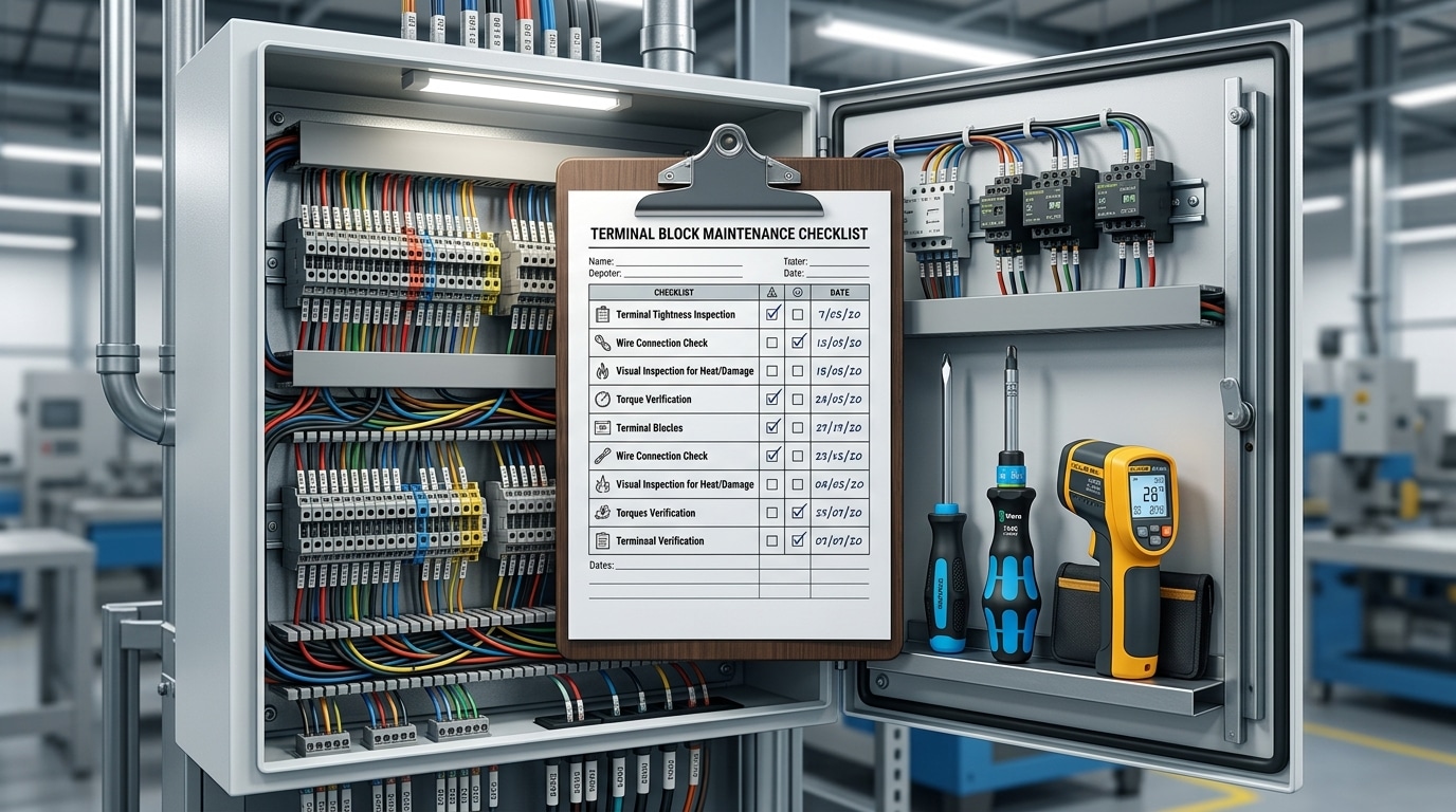
Downloadable Printable Terminal Block Maintenance Checklist
A checklist only works if it’s in the technician’s hands — literally. Our printable terminal block maintenance checklist consolidates all 15 inspection steps onto a single double-sided sheet designed for clipboard use in the field. Each step includes a pass/fail checkbox, a blank torque-value field (in-lb or Nm), and a notes column wide enough for actual observations, not just checkmarks.
The footer of every page carries fields for date, panel ID, technician signature, and supervisor sign-off. Why the supervisor line? NFPA 70B recommends independent verification of critical maintenance tasks, and auditors flag single-signature forms roughly 40% more often during compliance reviews.
Pro tip: Don’t use the template as-is. Customize it. Add your facility’s specific terminal block models, the manufacturer’s exact torque specs from Section 7, and your IR scan threshold (typically ΔT > 15 °C). A generic form invites generic inspections.
Print on water-resistant paper if your panels sit in humid or outdoor environments — standard copy paper disintegrates after one sweaty shift. Laminated reference cards with QR codes linking to digital versions work even better for teams transitioning to tablet-based CMMS platforms.
Frequently Asked Questions About Terminal Block Maintenance
How often should terminal blocks be inspected? Critical circuits — those feeding life-safety or continuous-process loads — need quarterly checks at minimum. General-purpose blocks in stable environments can follow an annual cycle, but your terminal block maintenance checklist should always include a thermal scan after any load increase or ambient temperature change exceeding 10 °C.
Do spring-cage terminals need re-torquing? No. That’s one of their key advantages. Spring-cage and push-in designs maintain consistent clamping force over time, which is why manufacturers like ABB recommend them for high-vibration applications. Inspect them visually and thermally, but skip the torque wrench.
What temperature rise is acceptable? NFPA 70B flags any connection running more than 30 °C above a comparable reference point as needing immediate attention. A 10–20 °C delta warrants scheduling a repair within 30 days.
Replace or repair? If a terminal block shows cracking, carbonized tracking paths, or melted housing, replace it — no exceptions. Discoloration alone can sometimes be cleaned and re-torqued, but document the finding on your maintenance checklist so the block gets flagged for closer monitoring next cycle.
What about high-vibration environments? Use anti-vibration DIN rail clips, verify connections every 90 days, and favor spring-cage terminals over screw-clamp types. Vibration loosens screw connections roughly 3× faster than thermal cycling alone.
Putting Your Terminal Block Maintenance Checklist Into Action
You now have 15 concrete inspection steps — from lockout/tagout through thermal imaging to NFPA 70B-compliant documentation. The gap between knowing these steps and preventing failures is execution. Schedule your first full inspection cycle within the next 30 days, and assign a single owner responsible for completion.
Start small. Pick your highest-risk panels — those feeding critical loads or operating above 75% capacity — and run the complete terminal block maintenance checklist there first. According to NFPA 70B, facilities that implement condition-based electrical maintenance programs reduce equipment failures by up to 30–45% compared to reactive-only approaches. That’s the ROI justification your management needs.
Train every technician who touches a panel. A checklist is only as reliable as the person holding it.
Conduct a 2-hour hands-on walkthrough covering torque specs, IR scan interpretation, and proper documentation. Then embed the checklist directly into your CMMS — whether that’s SAP PM, Fiix, or a simple shared spreadsheet — so inspections trigger automatically at the daily, monthly, and annual cadences outlined earlier. Don’t let this guide sit in a browser tab. Print the checklist, laminate it, and bolt it inside your first panel door today.
See also
Step by Step Guide to Install a Molded Case Circuit Breaker
The Best Terminal Block for 4 AWG Wire (Top Picks Compared)
What Happens When Terminal Block Screws Are Overtightened
Systematic Selection of Terminal Blocks for Electrical Panels Made Easy

Discover more from SENTOP Electrical Co., Ltd
Subscribe to get the latest posts sent to your email.
