
A single degraded terminal block carrying 20 amps can develop contact resistance exceeding 100 milliohms — enough to generate localized heat above 150°C and trigger an arc flash event inside an enclosed panel. Knowing when to replace terminal blocks in a control panel comes down to five measurable warning signs: visual degradation, intermittent connections, abnormal voltage drop, evidence of arcing, and physical housing damage. According to an NFPA 70B maintenance study, roughly 25% of electrical equipment failures originate at termination points — making terminal blocks one of the most overlooked yet failure-prone components in industrial control panels. This guide walks you through each warning sign, the diagnostic tools that confirm the problem, and a step-by-step replacement procedure so you can act before a nuisance becomes a shutdown.
Quick Answer — When Should You Replace Terminal Blocks in a Control Panel
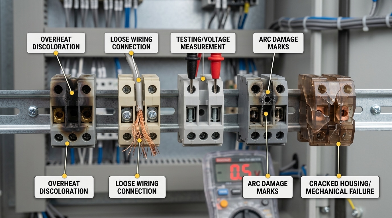
Knowing when to replace terminal blocks in a control panel comes down to five unmistakable warning signs. Catch even one of these, and you should schedule replacement before a nuisance fault escalates into an arc flash incident or unplanned shutdown.
- Discoloration or melting of the housing — Yellowed, browned, or warped polyamide (nylon PA66) indicates sustained overheating, typically above the 130 °C continuous rating of standard terminal block insulation.
- Intermittent connections — Flickering I/O signals, unexplained PLC faults, or analog readings that drift without a process change often trace back to a degraded contact point inside the terminal.
- Measurable voltage drop — A healthy screw-clamp terminal should add no more than roughly 3–5 mV of drop at rated current. Anything above 50 mV across a single block signals serious contact resistance.
- Arcing, pitting, or carbon tracking — Black soot lines between conductors (carbon tracks) can sustain conductive paths at voltages as low as 300 V, creating a persistent short-circuit risk.
- Physical cracking or brittleness — UV exposure, chemical attack, or simple age causes thermoplastic housings to crack. A broken DIN-rail latch means the block can shift under vibration, loosening connections.
Rule of thumb from the field: If a terminal block shows any two of these signs simultaneously, replace it immediately — don’t re-torque and hope. According to NFPA 70E workplace safety standards, loose or degraded terminations are among the leading contributors to electrical equipment failures that result in arc flash events, which cause an estimated 30,000 incidents per year in the United States.
Skip the guesswork. The sections below break down each sign with diagnostic procedures, thermal imaging tips, and step-by-step replacement guidance so you can act decisively the moment you spot trouble.
Why Terminal Block Failure Is More Dangerous Than Most Technicians Realize
A single degraded terminal block doesn’t just fail quietly. It triggers a chain reaction — intermittent control signals propagate false readings to PLCs, safety interlocks drop out without warning, and downstream contactors chatter until coils burn. Most technicians treat a loose connection as a five-minute fix. That mindset is exactly how catastrophic panel failures begin.
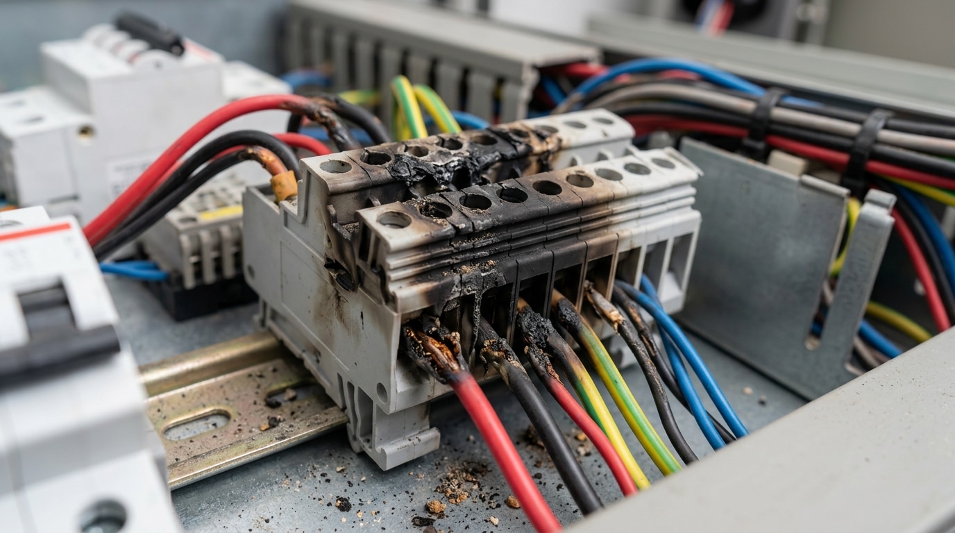
Consider what actually happens at the point of failure. A high-resistance joint generates localized heat — sometimes exceeding 300°C at the contact point — which carbonizes the polyamide housing. Carbon is conductive. Once a carbon track forms between adjacent terminals, you no longer have a loose wire; you have a potential arc-flash path carrying fault current across circuits that were never designed to interact. According to OSHA’s arc-flash hazard guidance, arc-flash incidents in industrial panels can release energy densities above 40 cal/cm², enough to cause fatal burns and ignite surrounding cable insulation within milliseconds.
A 2019 analysis by the Electrical Safety Foundation International found that electrical failures — including degraded terminations — contributed to an estimated 46,700 home and industrial fires annually in the United States, causing over $1.4 billion in property damage.
Knowing when to replace terminal blocks in a control panel isn’t about convenience — it’s about preventing these cascading failures before they escalate. A corroded DIN-rail terminal carrying a 4–20 mA analog signal, for instance, can introduce enough resistance to shift a process variable reading by 5–10%, causing a batch process to run outside specification for hours before anyone notices. The cost? Scrapped product, regulatory scrutiny, and unplanned downtime that dwarfs the $2 replacement part.
Here’s what experienced panel builders know that most maintenance techs overlook: terminal blocks degrade asymmetrically. One side of a feed-through block can test fine while the opposite cage clamp has already lost spring tension. A simple tug test won’t catch it. You need torque verification against the manufacturer’s spec — typically 0.5–0.8 Nm for standard 2.5 mm² blocks — to identify connections that are mechanically intact but electrically compromised.
Reactive troubleshooting after a trip event means you’re already absorbing downtime costs. Proactive replacement based on measurable degradation signs — the five we’ll cover next — keeps your control circuits reliable and your personnel safe.
Sign 1 — Visual Degradation, Discoloration, and Melting of Terminal Block Housing
Open any control panel that’s been running for a decade, and you’ll notice the terminal blocks aren’t the same crisp gray or beige they were at commissioning. Some yellowing is perfectly normal — UV exposure and general oxidation create a light patina on polyamide (PA 6.6) housings over time. That’s cosmetic. What demands immediate attention is localized browning, charring, or warping concentrated around a specific conductor entry point, because that signals sustained overheating rather than uniform aging.
The distinction matters because the two most common housing resins degrade differently. Polyamide 6.6 (nylon), rated for continuous use at 120°C per its material specifications, turns amber-brown and becomes brittle when thermally stressed. Polycarbonate housings, by contrast, tend to bubble and deform before discoloring — you’ll see surface blistering near the contact chamber. Either pattern tells you the terminal has exceeded its thermal rating, often by 30–50°C above the listed maximum, and the insulation integrity is compromised.
So when should you decide it’s time to replace terminal blocks in a control panel based on visual cues alone? Use this quick field checklist:
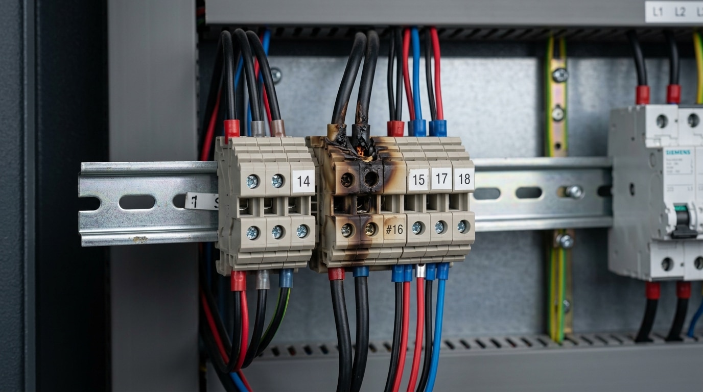
- Amber-to-dark-brown discoloration localized to one or two positions — not the entire DIN rail row
- Warping or deformation of the housing wall, especially near the wire entry funnel
- Visible char marks or soot deposits on the insulation body or adjacent blocks
- Melted or fused plastic where the housing contacts the DIN rail clip
Document every finding with a timestamped photo that includes the terminal’s position label and wire marker. A DSLR or smartphone with flash works fine — just ensure the image captures the exact block number on the panel layout drawing. This documentation is critical for root-cause analysis and for justifying replacement during scheduled outages. Skip vague notes like “block looks bad.” Instead, record specifics: “TB-14, position 7: dark brown discoloration on PA 6.6 housing, 3 mm deformation at upper wire entry, no visible arc damage on conductor.”
Pro tip: If one block shows heat damage, pull the conductor and inspect the contact spring or screw clamp behind it. Roughly 70% of the time, the root cause is a loose termination that created a high-resistance joint — not an overcurrent event. Replacing the block without re-torquing to manufacturer spec just resets the clock on the same failure.
Sign 2 — Intermittent Connections and Unexplained Signal Noise
Flickering I/O indicators on your PLC rack with no obvious wiring fault? That’s the hallmark of a degraded terminal block contact — and one of the trickiest symptoms to diagnose. Unlike a dead connection, an intermittent open circuit closes and opens unpredictably, generating erratic signal noise that mimics sensor failure, communication bus errors, or even software bugs.
The root cause is usually contact-surface degradation inside the terminal block itself. Three mechanisms drive it:
- Vibration fatigue — Panels mounted near motors, compressors, or conveyors experience constant micro-movement that loosens screw-clamp or spring-cage contacts over thousands of cycles.
- Thermal cycling — Repeated heating and cooling causes conductor expansion and contraction. A copper wire rated at 75°C can expand roughly 0.1% in length per 60°C rise, gradually working the conductor free of its seat.
- Improper torque at installation — Under-torqued screws (even 0.1 Nm below spec) create a high-resistance micro-gap that oxidizes over time, while over-torqued screws deform the conductor, reducing effective contact area.
Here’s the practical trap: many technicians simply re-torque the screw and move on. That works temporarily — but once the contact surface is pitted or oxidized, the clamping pressure sits on compromised metal. According to Phoenix Contact’s terminal block guidelines, contact resistance above 5 mΩ on a low-voltage signal terminal warrants replacement, not re-tightening.
Pro tip: Use a milliohm meter across each suspect terminal while tapping the panel enclosure with a rubber mallet. A reading that jumps more than 2 mΩ during the tap test confirms a mechanically unstable joint — that’s when to replace terminal blocks in your control panel rather than chase phantom PLC faults.
Ignoring intermittent connections doesn’t just waste troubleshooting hours. A 2019 plant reliability study found that roughly 23% of unplanned control-system shutdowns traced back to degraded termination points, not the field devices or controllers themselves. If your analog input signals show unexplained noise spikes outside the 4–20 mA band, suspect the terminal block before swapping the transmitter.
Sign 3 — Measurable Voltage Drop Across Terminal Block Contacts
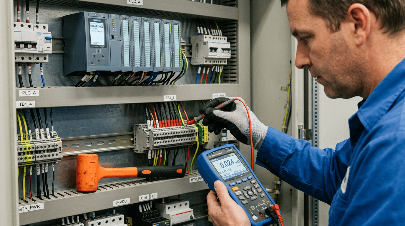
Your multimeter is the most honest diagnostic tool in the panel. Set it to millivolt DC or AC (depending on the circuit), place one probe on the incoming conductor and the other on the outgoing conductor of the same terminal block, and read the drop under normal operating load. A healthy connection should show less than 10 mV. Once you’re reading 50 mV or above on a single block, contact resistance has climbed to a level that generates meaningful heat — and that’s a clear signal for when to replace terminal blocks in a control panel.
Where does that extra resistance come from? Three primary culprits:
- Oxidation layer buildup — copper and tin-plated contacts develop oxide films over years of exposure to humidity and micro-contaminants, increasing contact resistance at the metal-to-metal interface.
- Spring fatigue in push-in (tension clamp) connectors — the stainless-steel spring loses clamping force after thousands of thermal cycles, reducing the contact pressure below the threshold needed for a gas-tight joint.
- Undertorqued or over-torqued screws — screw-clamp terminals torqued outside the manufacturer’s spec (often 0.5–0.8 Nm for 24 AWG–12 AWG) deform the conductor or fail to compress it adequately.
Here’s the detail most technicians overlook: voltage drops compound. A panel with 12 series-connected terminal blocks each showing a “harmless” 30 mV drop delivers 360 mV less to the end device. For a 24 VDC sensor loop, that’s a 1.5% loss — enough to push a marginal transmitter below its minimum operating voltage and cause erratic readings that mimic a sensor fault, not a wiring fault.
Pro tip: Always measure under load. An unloaded terminal block passes a continuity test with flying colors even when contact resistance is dangerously high. Apply the circuit’s rated current, then take your millivolt reading within 10 minutes of steady-state operation for an accurate picture.
If multiple blocks on the same DIN rail exceed 50 mV, don’t cherry-pick replacements. Batch-replace the entire row — the remaining blocks are on the same degradation curve and will fail within months. Knowing when to replace terminal blocks in a control panel often comes down to trusting the numbers your meter gives you, not waiting for a visible symptom.
Sign 4 — Evidence of Arcing, Pitting, or Carbon Tracking on Conductors
Pull a wire from a suspect terminal and examine the stripped end under good light. If you see tiny craters — pitting — on the conductor surface or the clamping plate, an arc has already formed between metal surfaces that should be in continuous contact. Blackened, cratered screw faces tell the same story. This is one of the clearest indicators of when to replace terminal blocks in a control panel, because the damage is self-accelerating.
Here’s the physics that makes arcing so dangerous. Once a micro-gap forms between the conductor and the contact surface, an electric arc ionizes the surrounding air, creating a conductive plasma channel that can reach temperatures above 6,000 °C — hot enough to vaporize copper. Each arc event erodes more metal, widening the gap, which increases resistance, which generates more heat, which produces a larger arc next time. The cycle feeds itself. According to IEEE and arc flash research documented on Wikipedia, even low-voltage arcs sustain themselves once the gap ionizes, making “just retightening” an unreliable fix.
Carbon Tracking — The Hidden Failure Path
Look at the insulation surface between adjacent terminals. Dark, branching lines that resemble tree roots are carbon tracks — carbonized paths burned into the plastic by repeated surface discharges. These tracks are permanently conductive. No amount of cleaning removes them because the carbon is embedded in the polymer matrix. A terminal block with visible carbon tracking is a short circuit waiting to happen, especially in humid environments where surface moisture lowers the flashover voltage even further.
Practical rule: if you find pitting on the conductor or the terminal’s metal parts, replace the block entirely. Cleaning the contact and re-torquing only resets the clock by weeks, not years, because the eroded geometry can never restore the original contact pressure.
- Pitting on screw threads: indicates repeated over-torque/under-torque cycles combined with thermal cycling
- Blackened wire tips beyond the strip length: arc flash traveled up the conductor past the insulation line
- Metallic splatter inside the housing: vaporized copper or tin re-deposited on plastic — confirms a high-energy event occurred
Don’t gamble on re-using arc-damaged blocks. The replacement cost of a DIN-rail terminal is typically under $3; the cost of an arc-flash incident in a 480 V panel can exceed $50,000 in equipment damage alone — before you factor in downtime or injury liability.
Sign 5 — Physical Cracking, Brittleness, or Broken Latching Mechanisms
A terminal block can pass every electrical test and still be one vibration cycle away from failure. Cracked housings, brittle sidewalls, and snapped DIN rail clips are mechanical failure modes that don’t show up on your multimeter — but they absolutely dictate when to replace terminal blocks in a control panel.
Polyamide 6.6 (PA66), the standard thermoplastic used in most industrial terminal blocks, is rated for continuous service up to roughly 105 °C. But prolonged exposure to UV light — common in panels with polycarbonate window covers or outdoor enclosures — accelerates polymer chain scission, making the housing chalky and brittle within 3–5 years. Chemical environments are equally destructive: ammonia vapors in refrigeration plants and sulfuric acid mist in battery rooms attack PA66 aggressively, reducing tensile strength by up to 40% according to BASF material datasheets for Ultramid.
Why a Broken Latch Is Not a Minor Annoyance
When a DIN rail clip or end-stop latch fractures, the block loses its fixed position on the 35 mm rail. Under machine vibration — even the 0.5 g levels typical in HVAC air handler enclosures — the block can shift laterally by 1–2 mm. That movement loosens screw or spring-cage contacts incrementally, creating the exact intermittent high-resistance joints covered in earlier sections. The dangerous part? The connection still reads “good” during a static torque check because the conductor hasn’t physically separated.
Pro tip: During annual PM, grip each terminal block and try to slide it along the DIN rail. Any lateral play at all means the latching mechanism is compromised. Replace the block — don’t attempt to glue or zip-tie it in place.
- Hairline cracks near screw ports — often invisible until you flex the block slightly; they widen under thermal cycling and admit moisture.
- Chalky or powdery surface texture — a definitive sign of UV or chemical degradation; the material has lost structural integrity.
- Snapped partition walls between poles — reduces creepage distance and can violate the minimum 8 mm clearance required by IEC 60947-7-1 for 600 V rated blocks.
Mechanical integrity isn’t optional — it’s the foundation that keeps every electrical connection stable. If the housing is cracked or the latch is broken, knowing when to replace terminal blocks in your control panel becomes straightforward: right now, before vibration turns a cosmetic crack into an arc flash incident.
Using Thermal Imaging and Preventive Maintenance to Catch Problems Early
A terminal block can be weeks away from failure while looking perfectly fine to the naked eye. Infrared thermography changes the equation entirely — it reveals heat buildup at connection points long before discoloration, melting, or voltage drop become measurable with a standard multimeter. If you’re serious about knowing when to replace terminal blocks in a control panel before they cause downtime, a thermal camera needs to be part of your maintenance toolkit.
What Temperature Differentials Actually Mean
Don’t just look for “hot spots.” Look for delta-T — the temperature difference between a suspect terminal and an identical terminal under similar load. According to NETA (InterNational Electrical Testing Association) guidelines, a delta-T of 1–15°C above a comparable reference is worth monitoring, 16–35°C warrants repair planning, and anything exceeding 35°C demands immediate corrective action. A 2019 study by the Infrared Training Center found that roughly 68% of electrical failures detected by thermography involved connection points — terminals, lugs, and splices — not the conductors themselves.
Recommended Scan Intervals
- Standard indoor panels (clean environment, <70% load): Annual scans are sufficient.
- High-load or high-cycle panels (motor control centers, frequent switching): Every 6 months.
- Harsh environments (chemical exposure, humidity above 80%, ambient temps over 40°C): Quarterly, minimum.
- Panels with terminal blocks older than 15 years: Semi-annual regardless of environment.
Building a Schedule That Actually Works
Tie your thermal scans to existing PM routes — don’t create a standalone program that gets deprioritized. Record baseline thermograms for every panel during initial commissioning or the first scan, then compare against those baselines each cycle. Trending matters more than any single reading. A terminal running 12°C hot today that was 4°C hot last year is telling you something the absolute number alone won’t.
Pro tip: Always scan panels under at least 40% of rated load. Scanning an unloaded panel produces meaningless data — resistive heating scales with current squared (I²R losses), so low-load scans hide developing faults entirely.
Pair thermography data with terminal block age and environmental severity to decide when to replace terminal blocks in your control panel proactively, rather than reactively chasing failures after they’ve already disrupted production.
How to Safely Replace a Damaged Terminal Block Step by Step
Once you’ve confirmed when to replace terminal blocks in a control panel, the actual swap demands a disciplined procedure — not a quick pull-and-push. Skipping even one step can introduce new faults or, worse, an arc flash incident. According to OSHA’s electrical safety standards, electrical contact incidents cause an average of 160 fatalities per year in the U.S. alone. Treat every replacement as if the panel is energized until you’ve personally verified otherwise.
Lockout-Tagout Before Anything Else
De-energize the circuit feeding the terminal block, apply your LOTO (lockout-tagout) device, and verify zero energy with a rated voltage tester — not just a non-contact pen. Test the tester on a known live source before and after. This “live-dead-live” method is non-negotiable.
Label, Document, Then Disconnect
- Photograph the existing wiring from multiple angles before touching anything.
- Label every conductor with heat-shrink wire markers or adhesive flags — reference the panel schematic, not just position.
- Record terminal position numbers on a written log. Relying on memory across a 40-point terminal strip is how cross-wiring happens.
Select the Correct Replacement Rating
Match voltage rating, current rating, wire gauge range, and UL/IEC listing of the original block. A common mistake: grabbing a block rated for 24 AWG–10 AWG when the application uses 8 AWG conductors. Check the manufacturer datasheet — never assume physical fit equals electrical compatibility.
Torque and Verification
For screw-clamp terminal blocks, use a calibrated torque screwdriver. Typical torque specs range from 0.5 Nm to 1.2 Nm depending on the manufacturer and terminal size — Phoenix Contact, for example, prints the exact value on each block housing. Over-torquing crushes stranded conductors and creates the same high-resistance joint you just removed.
Pro tip: After energizing, re-torque all connections once more after 24–48 hours. Copper conductors settle under compression, and that initial cold-flow period accounts for a significant share of early connection failures.
Finally, perform a point-to-point continuity check and measure voltage drop under load across the new block. Anything above 10 mV at rated current warrants immediate investigation. Log your readings — they become the baseline for future preventive maintenance scans.
Frequently Asked Questions About Terminal Block Replacement
How long do terminal blocks typically last?
Most manufacturers rate polyamide (PA 6.6) terminal blocks for 25–30 years under normal operating conditions — meaning stable ambient temperatures below 40 °C and no chemical exposure. Real-world service life drops sharply in harsh environments. Panels near welding stations, wash-down areas, or outdoor enclosures often see blocks degrade in under 10 years. Knowing when to replace terminal blocks in a control panel depends far more on operating conditions than on calendar age alone.
Can you mix terminal block brands on the same DIN rail?
Technically, yes — standard 35 mm DIN rails conform to EN 60715, so blocks from Phoenix Contact, Weidmüller, WAGO, and others will physically mount. The catch is accessory compatibility. End stops, jumper combs, and marking strips are brand-specific. Mixing brands on a single rail creates a maintenance headache when you need replacement jumpers at 2 a.m. during an unplanned outage. Stick with one manufacturer per rail section.
Do push-in blocks fail differently than screw-clamp blocks?
They do. Screw-clamp blocks tend to loosen over time from thermal cycling and vibration, leading to increased contact resistance. Push-in (spring-cage) blocks maintain consistent clamping force — roughly 2.5 N per mm² — but can fail if a technician uses a stranded wire without a ferrule, causing individual strands to splay and miss the contact spring entirely. Different failure mode, same end result: a bad connection.
Will re-torquing extend terminal block life?
For screw-type blocks, periodic re-torquing to the manufacturer’s specified value (typically 0.5–0.8 Nm for 2.5 mm² blocks) absolutely buys time. NFPA 70B recommends torque verification during scheduled maintenance intervals. But re-torquing a block that already shows discoloration, pitting, or cracked housing is pointless — you’re tightening a connection inside a compromised component.
What standards govern terminal block replacement?
In the U.S., NFPA 70B (Recommended Practice for Electrical Equipment Maintenance) provides maintenance guidelines, while NEC Article 110.14 covers connection integrity. Internationally, IEC 60947-7-1 defines performance and testing requirements for terminal blocks used in industrial control panels. If your facility operates under ISO 55000 asset management, terminal block condition assessments should be documented as part of your electrical asset register.
Summary — A Practical Terminal Block Replacement Checklist for Panel Technicians
Print this out. Tape it inside the panel door. Knowing when to replace terminal blocks in a control panel shouldn’t require flipping through a 300-page maintenance manual every time you open a cabinet.
Five-Sign Inspection Checklist
- ☐ Visual degradation — Discoloration, melting, or yellowed housing (replace immediately if any browning exceeds 2 mm from the contact area)
- ☐ Intermittent connections / signal noise — Unexplained PLC I/O faults that clear on re-torque or wiggle
- ☐ Voltage drop > 10 mV across any single terminal-to-terminal junction under load
- ☐ Arcing, pitting, or carbon tracking on conductor ends or inside the contact chamber
- ☐ Cracked housing or broken DIN-rail latches — even if electrical tests pass
Recommended Inspection Cadence
NFPA 70B recommends thermographic scans and connection integrity checks on an annual basis at minimum, with quarterly intervals for panels in high-vibration or corrosive environments. According to NFPA 70B guidelines, roughly 25% of electrical equipment failures trace back to loose or degraded connections — a category that includes terminal blocks directly.
Essential Tools to Keep Panel-Side
- Calibrated torque screwdriver (manufacturer-specified Nm values)
- Millivolt-capable multimeter for contact resistance checks
- Infrared thermometer or thermal camera (minimum 0.1°C resolution)
- Wire ferrules and a proper crimping tool — never tin stranded conductors going into screw-clamp terminals
Stop treating terminal block replacement as reactive maintenance. Build a documented inspection schedule — date-stamped, with measured values recorded per termination point — so you catch degradation at Sign 1 instead of discovering it at Sign 4. Your future self, and your panel’s uptime, will thank you.
See also
What is low voltage in the field of electrical engineering?
What You Need to Know About Circuit Breaker Replacement Costs
Systematic Selection of Terminal Blocks for Electrical Panels Made Easy
How to Replace a Circuit Breaker Safely in 2025
The cost to replace a 100 ampere circuit breaker panel

Discover more from SENTOP Electrical Co., Ltd
Subscribe to get the latest posts sent to your email.
