
Torque is an input
It is not a direct test of connection quality. Thread friction, geometry and wire preparation change the result.

Overtightening can damage the clamping system instead of improving it. Too much torque may strip threads, deform the clamp or current bar, crack the housing, or harm wire strands. The joint may work at first but fail to hold the intended pressure. Use the value and wire preparation stated for the exact terminal model.
Screw terminals with a crimped wire. Photo: Simon A. Eugster (LivingShadow), via Wikimedia Commons, CC BY-SA 3.0. Responsive crop only.
A screw terminal turns tool torque into clamping force. Once the allowed range is exceeded, added force may damage the wire or terminal instead of improving the electrical joint.
Check the wire metal, size, strand type, strip length, ferrule rule, number of wires and driver profile. These details affect how the clamp works. Do not copy a value from a block that only looks similar.
It is not a direct test of connection quality. Thread friction, geometry and wire preparation change the result.
Threads, the clamp, current bar, housing or wire strands may deform before heat appears.
A hot point can also come from overload, poor cooling, corrosion or another bad connection.
If a part is cracked, stripped, distorted or heat damaged, follow the equipment maker’s replacement plan.
The screwdriver does not press on the wire by itself. The screw, thread, cage, pressure plate and current bar form a system. Each design converts torque in a different way.
The operator applies torque in newton-metres (N·m). The bit and tool range must suit the screw and stated value.
Part of the input overcomes friction. Surface finish, thread shape and any approved compound affect the force that remains.
The mechanism moves a cage or pressure plate. It presses the approved wire against the terminal’s current path.
The correct range creates stable pressure without crushing the wire or passing the terminal’s mechanical limit.
The wire may move or have too little true contact area. Resistance may rise during service.
This is an undertorque path. It is not proof that extra force beyond the range is safe.
The terminal is made to hold the approved wire under its stated conditions.
Correct torque still depends on correct strip length, wire type and assembly.
Threads may strip. The clamp, wire or housing may deform. The joint can then lose the pressure it was meant to keep.

Large and small screw terminals may use different thread sizes, cages, pressure plates and wire ranges. Even two products with a similar shape can have different instructions.
DIN-rail power terminals. Photo: Dmitry G, via Wikimedia Commons, CC BY-SA 3.0. Responsive crop only.
The exact failure depends on terminal design. Use this map to guide a qualified inspection. It is not a photo-based diagnosis.
The wrong bit or too much force can damage the screw head. The next tool may slip or fail to apply the stated value.
Decision: Follow the maker’s replacement method. Do not force a larger bit into the head.
A screw may spin, feel uneven or fail to hold the stated torque. Internal thread damage may not be easy to see.
Decision: A terminal that cannot retain its set point needs engineering review and usually replacement.
The cage, pressure plate or current path can bend. Added tool force then stops becoming useful contact pressure.
Decision: Replace distorted parts as the terminal and equipment maker directs.
Excess pressure may cut strands or reduce the useful wire section. Stray strands can also appear after poor preparation.
Decision: Replace the damaged wire end. Re-strip and terminate only if the approved work plan allows it.
A ferrule is not always needed or allowed. If it is approved, its size and crimp must match the wire and terminal.
Decision: Do not reuse a split, deformed or heat-damaged termination.
The insulating body, partition or mounting foot may crack. Distortion may affect spacing, touch protection or rail fit.
Decision: Replace compromised insulation. Glue does not restore a product rating.
| What you find | What it may mean | What it does not prove | Safe disposition |
|---|---|---|---|
| Screw spins or will not hold | Thread, cage or screw damage is possible. | It does not show that the wire is still clamped well. | Stop using that point. Follow the OEM replacement plan. |
| Crack or shifted clamp | The housing or inner parts may have passed their mechanical limit. | A small crack is not harmless because the circuit still works. | Replace the affected terminal and inspect nearby parts. |
| Cut or missing strands | Wire preparation or clamp force damaged the conductor. | Continuity does not prove full current capacity. | Replace the damaged wire end under the approved method. |
| Heat color or melted insulation | Excess resistance, overload or another thermal fault occurred. | The mark alone does not prove overtorque. | De-energize, preserve evidence and perform root-cause review. |
| No visible damage | There may be no damage, or the damage may be internal. | Appearance cannot recover the original installation torque. | Use the maker’s inspection method. Do not improvise a click test. |

The following values belong only to the named products and their instructions. They show why a shop-wide guess is unsafe. They are not a torque table for other parts.
These values differ by roughly fifty times. The difference comes from the product design, not a simple “small wire versus large wire” rule. Use the model-specific torque guide as a buying checklist, then confirm the maker’s live document.
Installed cabinet terminal block. Photo: tony_duell, via Wikimedia Commons, CC BY 2.0. Responsive crop only.
Do not start by loosening the screw. First make the circuit safe and keep useful evidence. The full equipment instructions control the repair.
De-energize, isolate, lock/tag where needed, verify no voltage and discharge stored energy. Use qualified staff.
Record the catalog number, wire, ferrule or lug, strip length, tool, set point and assembly record.
Look for thread trouble, cracks, clamp shift, missing strands, heat color, melted plastic and wire movement.
Use the OEM method. Replace damaged parts or wire ends. Do not add glue, washers, threadlocker or extra torque.
Reassemble with approved parts. Complete the required checks, restore barriers and update the service record.
Stripped threads, a cracked body, distorted clamp, missing strands, melted insulation or loss of wire retention are stop signs. Inspect adjacent parts too.
Appearance is not proof. Do not back off and re-tighten by habit. Use the current terminal and equipment instructions.
Investigate load, wire fit, corrosion, cooling, contact resistance and protection. Use a full terminal failure analysis when evidence is mixed.

Heat damage proves that a connection needs investigation. It does not prove which fault started it. The photographer linked this example to an unsuitable aluminum-to-copper connection, not to overtightening.
A hot terminal may also result from overload, contamination, corrosion, poor conductor fit or cooling limits. See the focused guide to terminal-block overheating causes.
Burned terminals. Photo: Dmitry G, via Wikimedia Commons, dedicated to the public domain.
This is a process-control overview, not an installation procedure. For the full safe sequence, use the terminal-block wiring workflow and the equipment instructions.
Put the exact terminal and accessory codes in the drawing or bill of materials. Control document revisions.
Confirm metal, size, strand class, insulation, ferrule or lug, and wires allowed at each clamp.
Use the stated strip length. Do not nick strands, lose strands, leave stray strands or expose excess copper.
Match the driver profile and size. A poor fit can damage the screw before the target is reached.
Use a controlled torque tool whose working range covers the stated value. Follow its setting method.
Do not add lubricant, paste or threadlocker unless the terminal maker names the product and method.
Use the published value or range. Stop when the tool signals completion. Do not add a “safety turn.”
Check insertion, exposed copper, strands, housing and markers. Record the result when the quality plan requires it.
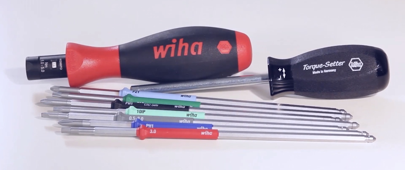
The tool must cover the needed value in its working range. The bit, condition and operator method also matter. A set number is not useful if the tool is damaged or used incorrectly.
TorqueVario-S torque screwdriver kit, shown for illustration only. Photo: Wiha Werkzeuge GmbH, via Wikimedia Commons, CC BY-SA 4.0. Responsive presentation only.
Some screw-clamp designs are documented as maintenance-free. Other equipment has a model-specific inspection plan. Use the terminal instructions, full equipment plan, service conditions and past results.
Thermal imaging can screen for abnormal heat under a useful load. It cannot identify overtorque by itself. It also cannot prove that an unloaded or lightly loaded connection is healthy.
Set inspection intervals from risk, load, duty, vibration, contamination, moisture and equipment needs. For a wider plan, use the terminal-block maintenance checklist.
Installed cabinet terminal block. Photo: tony_duell, via Wikimedia Commons, CC BY 2.0. Responsive crop only.
A standard scope is not a torque value. The ordered part, wire conditions and equipment file still control the joint.
Covers defined terminal blocks for round copper wires within its stated scope. It does not make one torque valid for all products.
Addresses certain screw-type and screwless clamping units. Product use still depends on the exact design and instructions.
Component compliance alone does not prove fit for every final product. Check the exact model and use conditions.
Connections must not damage wires. Exposed live work has strict limits. De-energization is the normal starting point.
These parts cover tool requirements and calibration methods. They do not create one recalibration interval for every shop.
A Recognized Component is assessed for stated use. Review its file and Conditions of Acceptability with the final equipment.
A clear request helps the supplier match the block, wire, tool and project evidence.
Too much torque may strip threads, damage the screw drive, deform the clamp or current bar, crack the housing, or harm wire strands. The joint may still work at first. Later, damaged parts may fail to keep the intended pressure.
No. Overtightening is first a mechanical fault. Resistance rises only if the damage harms the contact path, wire section or retained clamp force. A hot point can also have other causes, so diagnose the full circuit.
Look for a spinning screw, damaged threads, a cracked body, a shifted clamp, missing strands, abnormal wire crushing, heat color or wire movement. No visible mark does not prove that internal parts are sound.
Do not do this by habit. Loosening can disturb the joint and hide evidence. Make the circuit safe, identify the exact model, and use the terminal and equipment maker’s inspection or replacement method.
Not reliably. Static friction, settling and earlier damage change a later movement reading. An improvised click test is not a true record of the original installation torque. Follow the approved inspection method.
There is no universal value. Use the current maker value or range for the exact catalog number, wire and termination method. Also use the stated strip length, driver profile and number of wires per clamp.
No. Some screw-clamp designs are documented as maintenance-free. Set inspections from the terminal and equipment instructions plus a risk-based maintenance plan. Re-tighten only when those instructions allow or require it.
Replace parts as the maker directs when threads cannot hold, the housing or clamp is damaged, strands are cut, insulation is heat damaged, or the wire will not stay secure. Inspect nearby parts before release.
Send SENTOP the terminal plan, wire data, circuit duty, target market and quality needs. We can review the model and accessories, then align samples, labels, documents and supply requirements.
