
Terminal Block Failure Analysis: Causes & Diagnostic Steps
Terminal block failure analysis is not the act of replacing a burned connector or tightening a hot screw. It is an evidence-led process that separates the observed failure mode from the electrical, thermal or mechanical mechanism, isolates root and contributing causes, and then proves the corrective action worked.

Treat every symptom as a hypothesis—not a verdict
A hot terminal may reflect high contact resistance, excessive current, conductor sizing, phase imbalance, ambient heat or several factors at once. Preserve evidence, compare like-for-like conditions, use the measurement that can test the hypothesis, then check the exact terminal instructions before deciding to reterminate, replace or adjust anything.
Record the signature
Photograph the location and damage pattern. Capture circuit, load, environment, adjacent terminals and event history before disturbance.
Use equivalent points
Compare the same terminal type, phase or circuit function under a known load. A single absolute reading rarely explains the cause.
Choose evidence, not habit
Thermography screens for anomalies; four-wire resistance, voltage drop, load data and physical inspection answer different questions.
Close the loop
Replace damaged parts, correct the process or environment, then repeat the relevant checks under comparable conditions.
Hands-on inspection starts only after the circuit is de-energized, locked or tagged as required, and verified de-energized by a qualified person. Energized thermography or voltage-drop work belongs inside the site's approved electrical-safety program.
A useful diagnosis separates four different questions
“The terminal burned because it was loose” compresses an observation, mechanism and assumed cause into one sentence. A defensible analysis keeps them separate until the evidence connects them.
Failure mode
What physically happened? Examples include localized thermal damage, an intermittent open circuit, surface tracking, conductor pull-out, corrosion or a cracked housing.
Failure mechanism
How did the damage develop? Possible mechanisms include resistive heating, electrical discharge, chemical attack, mechanical overload or insulation degradation.
Root & contributing causes
Why was the mechanism allowed to occur? Look beyond the component to conductor preparation, selection, work instructions, tooling, environment and design.
Corrective verification
What changed, and what proves recurrence risk was reduced? Record repair details and repeat the relevant electrical or thermal comparison.
Evidence rule: a proposed root cause should explain the location, damage pattern, operating history and measurements together. If it explains only one observation—or relies on a generic threshold—it remains a hypothesis.
Common terminal block failure modes and what they actually prove
Visual evidence helps prioritize tests, but most signatures have more than one plausible cause. Use this matrix to build the next question—not to skip the investigation.
| Observed signature | Plausible mechanisms | Evidence to collect next | Do not assume |
|---|---|---|---|
| One clamp or conductor entry is discolored or melted | High contact resistance, damaged conductor, poor insertion, corrosion, clamp damage or localized external heat | Load, thermal pattern, comparable connections, voltage drop or four-wire resistance, conductor and clamp condition | That a loose screw is the only possible cause |
| Several adjacent poles and conductors run hot | Overload, phase imbalance, undersized conductor, enclosure temperature, grouping or product derating issue | Current by phase, conductor size, ambient temperature, enclosure airflow, adjacent loading and derating data | That tightening every terminal will solve it |
| Branching carbon paths or flash marks on insulation | Surface tracking, contamination, moisture, inadequate spacing for the actual application or a transient event | Clean photographs before wiping, residue source, enclosure condition, rating/spacing, event history and authorized insulation tests | That the housing can be cleaned and returned to service |
| Green, white or dark deposits on metal surfaces | Moisture, salt, chemical exposure, incompatible materials, plating damage or process contamination | Deposit location, ingress path, nearby materials, environmental history and product chemical-compatibility information | That abrasive cleaning will restore the plated contact |
| Cracked housing, stripped screw or deformed clamp | Overtightening, wrong tool, impact, side load, unsuitable temperature or chemical attack | Tool and process record, correct torque/insertion method, conductor routing, mounting and material compatibility | That the part is safe because continuity remains |
| Intermittent signal or conductor pull-out without visible heat | Incomplete insertion, wrong conductor/ferrule, unapproved multiple conductors, vibration, strain or damaged spring/clamp | Exact product instructions, conductor construction, strip length, ferrule, retention method, vibration and strain relief | That a continuity beep under no load proves a sound connection |
The terms “plausible” and “next” are deliberate. This table is a diagnostic planning aid, not a universal acceptance standard.
Heat patterns narrow the field—but current must stay in the picture
A resistive connection converts electrical power to heat. The relationship explains why load data is essential: a connection can look acceptable at light load and become much hotter when current rises. It also explains why the hottest point may be concentrated near a damaged contact surface.
P = I²R
At constant resistance, doubling current produces four times the resistive heating power. This equation does not directly predict terminal temperature; heat flow, conductor size, enclosure conditions and duty cycle also matter.
Localized hot point
A sharp peak at one connection can indicate elevated contact resistance. Confirm equivalent load and compare voltage drop, resistance and physical condition before naming the cause.
Distributed heating
Heat along a conductor or across several poles can point toward load, conductor sizing, phase imbalance, ambient conditions or insufficient thermal margin.
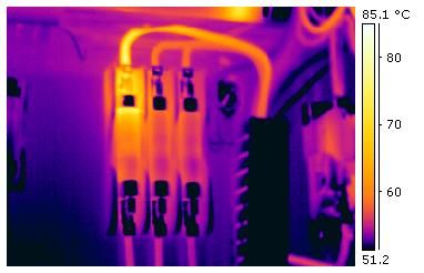

Preserve the as-found condition before the connection changes
Tightening, moving, cleaning or removing a conductor can erase the very evidence needed to explain the event. Record the scene at wide, medium and close range, then connect each image and measurement to a circuit identifier.
- Exact terminal catalog number, connection point, lot or revision when available
- Conductor material, size, strand class, ferrule or preparation, and permitted conductor count
- Operating current, load state, duty cycle, ambient temperature and enclosure conditions
- Adjacent terminal and phase comparisons, alarms, trips, process events and previous thermal records
- Instrument identity, range, calibration/status, measurement points and relevant settings
- Photos with scale, orientation and labels before any residue, clamp or conductor is disturbed
Thermography and energized voltage-drop checks require the circuit to be operating. They must be performed only by qualified personnel under the site's approved energized-work and PPE controls. Hands-on work follows de-energization, isolation, lockout/tagout as applicable, release of hazardous stored energy and test-based verification of the de-energized condition. See OSHA 1910.333.
Run terminal block failure analysis without destroying the evidence
The sequence keeps live screening separate from hands-on inspection and prevents a convenient repair from being mistaken for a verified root cause.
Define and control the scope
Identify affected equipment, circuit function, consequence and boundaries. Quarantine damaged components when necessary and decide whether warranty, insurance or laboratory evidence rules apply.
Capture operating context
Record alarms, load, current, ambient conditions, recent changes and comparable connections. Retrieve historical thermal images or maintenance data before they are overwritten.
Perform authorized online screening
If justified and permitted, qualified personnel may capture thermal patterns, current and voltage drop under a documented, stable load. If the safety controls are not in place, skip this step.
De-energize, isolate and verify
Disconnect every source, control hazardous stored energy, apply locks and tags as required, and use appropriate test equipment to verify exposed parts are de-energized, including possible backfeed or induced voltage.
Inspect before disassembly
Map discoloration, carbon paths, deposits, cracks, thread damage, insertion depth, loose strands, ferrule position, rail mounting, end stops, wire strain and adjacent damage.
Select the measurement that answers the question
Use comparable thermography, load/current data, an authorized voltage-drop check, four-wire low-resistance testing or insulation testing only when that method fits the isolated test object and product procedure.
Resolve exact product requirements
Check the current datasheet and instructions for ratings, conductor preparation, stripping length, ferrules, multiple-conductor allowance, torque or actuation method, mounting and environmental limits.
Correct, restore and verify
Replace damaged terminals and affected conductor as required, correct the process or environment, inspect the completed termination, then repeat relevant electrical or thermal checks under comparable load.
Each test answers a different diagnostic question
A continuity beep, thermal image and insulation-resistance value are not interchangeable evidence. The safe method and acceptance basis depend on the circuit, product and work condition.
| Method | What it can show | Required context | Key limitation |
|---|---|---|---|
| Visual and macro inspection | Damage origin clues, insertion, broken strands, contamination, plating loss, cracks, thread/clamp and mounting condition | De-energized, verified safe; photographs before cleaning or disassembly | Appearance alone rarely proves the electrical mechanism |
| Infrared thermography | Apparent temperature pattern and anomaly location under operating load | Qualified-person controls, known load, comparable points, emissivity/reflection awareness and repeatable image settings | It screens; overload, imbalance and high contact resistance can overlap |
| Current and load measurement | Overload, imbalance and whether the thermal observation was made at a meaningful operating condition | Correct instrument rating, phase/circuit context and duty-cycle record | Normal current does not rule out a high-resistance connection |
| Energized voltage drop | Excess voltage loss across a connection at the measured current | Authorized energized work, defined probe points, current at the same moment and comparison/baseline | No single millivolt value covers every terminal and load |
| Four-wire Kelvin resistance | Low resistance with test-lead and probe-contact effects largely excluded | De-energized isolated test object, understood parallel paths, repeatable contacts and manufacturer/baseline comparison | A generic milliohm limit is not a universal terminal-block specification |
| Insulation resistance or dielectric test | Insulation leakage or withstand behavior in the authorized test configuration | Fully de-energized system, isolated electronics/SPDs as required, approved test voltage and product/system procedure | A blanket 500 V test or universal megohm pass value can damage equipment or misclassify the assembly |
| Torque and hardware review | Whether the product, tool, conductor and documented installation method matched instructions | Exact terminal model, indicated torque/approved means, correct bit and inspection of threads, clamp and conductor | Tightening is not a diagnostic test; post-event movement torque is not proof of original installation torque |
For low-resistance work, a four-terminal Kelvin method removes lead and contact resistance from the measured voltage path. Even then, interpret results against the exact product, a commissioning baseline or comparable connections—not an invented universal limit.
Six shortcuts that erase evidence or create new risk
The source draft treated several planning values as universal rules. The safer approach is to state the test conditions, product basis and uncertainty.
A low-current continuity check can pass through a connection that produces excessive voltage drop or heating at operating current.
Load, conductor size, imbalance, ambient heat, corrosion and contact damage can produce similar thermal evidence.
Moving the screw changes the as-found state and may further damage a clamp, conductor or thread. Record and inspect first.
Acceptance depends on product, current, test configuration, baseline and applicable maintenance guidance. A single number is not universal.
Insulation test voltage and isolation steps come from the equipment manufacturer or applicable standard; connected electronics can be damaged.
Abrasives or unapproved chemicals may remove plating, hide the residue source or leave the contact geometry outside its qualified condition.
Move from “burned terminal” to a controllable process cause
The 5 Whys can organize a straightforward chain, but “five” is not a magic number. Stop only when the explanation is supported, within the investigation scope and connected to a corrective action that can be verified.
Illustrative evidence-led chain
Assume a qualified investigation finds localized heating at one connection, comparable current across phases, elevated voltage drop at that point, and—after de-energization—an incompletely seated ferrule. The following chain is a worked example, not a universal diagnosis.
- Why was the housing damaged? Local heat exceeded what the assembly could dissipate.
- Why was heat concentrated there? The connection showed higher electrical loss than comparable points at the same load.
- Why was the connection loss higher? The conductor was not fully engaged in the intended clamping area.
- Why was insertion incomplete? The preparation and insertion method did not provide a positive check against the product instruction.
- Why did the process allow that? The work instruction, training or inspection control omitted the exact strip/insertion criteria and traceable verification.
Check more than one cause branch
A fishbone or causal-factor review prevents the first plausible story from becoming the final answer. Test the branches that could explain the evidence.
Repair, reterminate or replace? Let damage and instructions decide
Once the evidence is captured, disposition should restore the connection to a known, qualified condition. “Still conducts” is not a reuse criterion.
| As-found condition | Preferred disposition | Follow-up evidence |
|---|---|---|
| Charred, melted, carbon-tracked or cracked insulation body | Keep isolated and replace the affected terminal/component; inspect neighboring poles, jumpers, rail and enclosure for transferred heat or contamination | Photos, part identification, damage extent, correct replacement and post-repair insulation/functional checks authorized for the assembly |
| Stripped thread, distorted clamp, broken spring or damaged rail latch | Replace rather than adding force or attempting to reshape the qualified connection mechanism | Tool/process review, conductor condition, mounting integrity and retention check allowed by the manufacturer |
| Heat-damaged conductor strands or insulation | Remove the damaged portion and reterminate, splice or replace using an approved method and sufficient conductor length | Clean conductor, correct preparation, approved ferrule if used, strip length, insertion and required torque/actuation record |
| Corrosion, pitting or visible plating loss in the current path | Preserve a sample when useful, replace damaged contact parts and correct the moisture, chemical or material-compatibility source | Ingress/environment action, compatible enclosure/product choice and comparable resistance or thermal verification |
| Surface contamination with no confirmed material damage | Identify the source and clean only by the product manufacturer's approved method; replace if the qualified surface cannot be restored | Before/after photos, product-approved cleaning record and the relevant electrical verification |
| No visible damage, but intermittent behavior or abnormal heat remains | Continue measurement and comparison; do not use tightening as the only test or return the circuit to service without resolving the abnormal evidence | Current/load, voltage drop or four-wire resistance, conductor/clamp inspection and a repeat measurement after corrective work |
Use standards to frame the work—not invent field thresholds
Product standards describe evaluated terminal-block characteristics and tests. Workplace rules govern how the inspection is performed. The exact product marking and current instructions remain central to the field decision.
OSHA 1910.333
OSHA's electrical work-practice rule covers de-energizing, lockout/tagout and qualified-person verification before exposed parts are treated as de-energized.
UL 1059
UL Solutions lists UL 1059 among standards used to evaluate terminal blocks. Do not substitute a generic connector torque table for the exact product data.
IEC 60947-7-1:2025
IEC 60947-7-1 covers terminal blocks for copper conductors within its scope. Type-test values are not automatically field alarm or replacement limits.
Indicated value, approved means
Where adopted requirements apply, achieve the manufacturer-indicated torque by an approved means. Use the exact product instructions; see the SENTOP torque specification guide.
Convert the root cause into five durable controls
Replacing the burned terminal is containment. Prevention changes the selection, installation, layout, maintenance or quality system that allowed the mechanism to recur.
Rate the complete application
Verify voltage, current, conductor range, connection technology, adjacent loading, ambient derating, approvals and environmental compatibility for the exact model.
Control conductor work
Specify material, strand class, strip length, ferrule and permitted conductor count. Use the correct tool and a positive insertion/retention check.
Remove mechanical load
Respect bend space, routing, end stops, wire support and strain relief so conductor weight, vibration or movement is not carried by the contact point.
Compare repeatable data
Create thermal or electrical baselines under documented loads and trend equivalent points. Set inspection intervals from risk, history and product guidance—not a universal calendar.
Close change-control gaps
Keep current datasheets, approved substitutions, tool status, training records, lot traceability and corrective-action ownership connected to the panel or CMMS record.
No universal re-torque program: connection technologies and manufacturer maintenance instructions differ. Some screw designs and spring connections are described as maintenance-free, while equipment-specific guidance may warn against disturbing healthy connections. Follow the current product and maintenance procedure rather than “tightening everything” on a fixed interval.
Build an evidence package that another engineer can reproduce
A useful report distinguishes observed facts from interpretation, states the acceptance basis and preserves uncertainty. It should show what was measured, under what condition, why the cause was selected and how the repair was verified.
If a warranty, insurance or serious incident review is possible, label and retain removed components under an agreed chain-of-custody process. Do not clean, destructively section or discard evidence until the responsible parties authorize it.
Review Terminal Block Selection
Asset identity
Panel, circuit, terminal model, pole/location, conductor, protective device and drawing reference.
Event & load
Timeline, alarms, operating current, duty, ambient conditions, recent changes and adjacent comparison.
Safety condition
Who performed the work, energized-screening authorization, isolation, lock/tag and verification record.
As-found evidence
Labeled wide and close photos, thermal images, residue, insertion, mounting and damage map before disturbance.
Measurement record
Instrument, status, method, test points, settings, load, ambient, raw values, comparison and uncertainty.
Product requirements
Datasheet revision, ratings, conductor preparation, approved connection method and applicable standard/code basis.
Cause statement
Failure mode, mechanism, root cause, contributing factors, evidence links and confidence/remaining alternatives.
CAPA & ownership
Containment, correction, systemic preventive action, responsible owner, due date and affected population.
Verification & disposition
Replacement details, inspection, comparable-load retest, retained sample location and formal return-to-service approval.
Send the evidence—not just a photo of the burned part
SENTOP can help map the failure evidence to a suitable terminal-block category, replacement requirement or application question. Final electrical-safety decisions and root-cause conclusions remain with the qualified personnel responsible for the equipment.
- Exact terminal part number and certification market
- Conductor material, size, strand class and ferrule
- Circuit voltage, normal/peak current and duty cycle
- Enclosure, ambient, vibration, moisture or chemical exposure
- Clear as-found photos and thermal/electrical comparisons
- Required replacement quantity and project timeline
Related terminal block resources
Use the failure evidence to correct the exact installation or selection variable rather than applying a generic fix.
Terminal block failure analysis questions
These answers deliberately avoid universal field thresholds. The exact product, circuit and safety procedure control the decision.
What is terminal block failure analysis?
Terminal block failure analysis is a structured process that identifies the observed failure mode, determines the physical or electrical mechanism, isolates root and contributing causes, and verifies corrective action. It combines preserved as-found evidence, operating context, product instructions, visual inspection and suitable measurements. Replacing a burned terminal without explaining why it failed is repair work, not a completed failure analysis.
What causes a terminal block to overheat?
Possible causes include elevated contact resistance, excessive current, an undersized or damaged conductor, incomplete insertion, corrosion, clamp damage, phase imbalance, high ambient temperature and inadequate application derating. A localized hot point can suggest a connection problem, while broader heating can suggest load or thermal-design issues, but neither pattern proves a root cause without load data and comparison.
What contact resistance value is acceptable for a terminal block?
There is no single milliohm value that applies to every terminal block, conductor and test configuration. Use the exact manufacturer limit when provided, a commissioning baseline, or equivalent connections measured with the same method and conditions. For very low resistance, a four-wire Kelvin method helps remove lead and probe-contact resistance, but parallel paths and test-current effects still need consideration.
Can a hot terminal block be fixed by tightening it?
Do not use tightening as the first diagnostic step. It changes the as-found state and may worsen damaged threads, clamps or conductors. Record the load and thermal pattern, make the equipment safe, inspect the exact connection and follow the manufacturer procedure. Heat-damaged components or conductors generally require replacement or retermination, followed by verification under comparable operating conditions.
Can a corroded terminal block be cleaned and reused?
Reuse depends on the product instructions and whether the qualified contact surface, plating, geometry and insulation remain intact. Pitting, plating loss, carbonization or damaged clamping parts normally points to replacement. If only removable contamination is present, identify and correct its source and use only a manufacturer-approved cleaning method before the required electrical verification.
Is thermal imaging enough to identify the root cause?
No. Thermography locates apparent temperature anomalies under the measured load. High contact resistance, overload, phase imbalance, conductor sizing and environmental conditions can create overlapping patterns. Record current, load, ambient conditions, emissivity-related settings and comparable points, then confirm the hypothesis with de-energized inspection and the appropriate electrical measurement.
Should screw terminal blocks be retightened regularly?
Not by a universal schedule. Connection designs and manufacturer maintenance instructions differ, and some screw technologies are described as maintenance-free. Indiscriminate re-torque can disturb a healthy connection or damage hardware. Build the maintenance task from the exact product guidance, equipment condition, adopted maintenance program, risk, vibration and service history.
When should insulation resistance or hi-pot testing be used?
Use these tests only when the product or system procedure authorizes them and the result answers a defined insulation question. The circuit must be de-energized, and electronics, surge devices and parallel paths may need isolation. Test voltage, duration, connection points and acceptance criteria come from the manufacturer or applicable standard—not a blanket 500 V rule.
Technical references
Use the current adopted edition, exact product documentation and local safety program. The links below support the workflow and its limits; they do not replace site-specific engineering judgment.
- OSHA 29 CFR 1910.333 — electrical work practices, de-energization, lockout/tagout and verification.
- OSHA 29 CFR 1910.147 — control of hazardous energy.
- UL Solutions connector certification — terminal-block standards including UL 1059.
- IEC 60947-7-1:2025 — official scope for terminal blocks for copper conductors.
- Fluke electrical thermography guide — load, comparison and thermal-pattern interpretation.
- Fluke insulation resistance guidance — test voltage, de-energization and connected-electronics limits.
- Megger four-wire resistance guidance — Kelvin measurement and parallel-path considerations.
- U.S. DOE root-cause analysis guidance — causal factors and corrective-action purpose.
- Phoenix Contact screw connection — an example of product-specific, maintenance-free connection design.
- Schneider Electric maintenance example — product-specific visual inspection and avoiding unnecessary connection disturbance.
External images are licensed for reuse as credited. For production performance and URL control, download, optimize and self-host copies in the SENTOP WordPress media library while preserving the creator and license attribution.
