
How to Fix a Loose Terminal Block Connection Safely
The safe fix is not simply “tighten the screw.” A qualified person must isolate every source, lock or tag the required disconnecting means, verify absence of voltage, and inspect the exact terminal and conductor before deciding whether to reterminate or replace them.
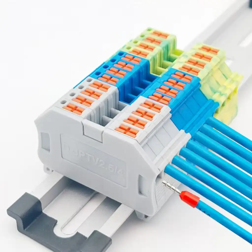
Isolate, lock or tag, and verify the parts are de-energized before touching a conductor or clamp.
Part number, conductor class, strip length and connection method determine the correct procedure.
Wire gauge alone does not determine screw torque; use the terminal or equipment instructions.
Retightening cannot restore a charred housing, pitted current path, stripped thread or failed spring.
How do you fix a loose terminal block connection?
This guide covers fixed low-voltage terminal blocks in control panels and similar equipment. It is an overview for people qualified for the specific equipment and hazards involved, not an energized-work instruction or a substitute for the employer's written energy-control procedure, shock and arc-flash risk assessment, equipment documentation or local law.
Symptoms point to a problem, not a proven cause
Heat, odor, intermittent operation and discoloration justify prompt investigation, but overload, conductor damage, contamination and component failure can create similar signs. Record the operating condition before shutdown when that can be done safely.
| Observed symptom | Possible mechanisms | First safe action |
|---|---|---|
| Intermittent load, signal dropout or contactor chatter | Low contact pressure, broken conductor, wrong conductor preparation, upstream control fault | Record the circuit state, then isolate and inspect the complete connection path |
| Localized discoloration, odor or damaged insulation | Connection resistance, overload, poor heat dissipation, contamination or previous arcing | Remove the equipment from service and plan replacement rather than blind retightening |
| Abnormal thermal pattern under representative load | Loose joint, unequal loading, overload, emissivity error, airflow or nearby heat source | Have qualified personnel document load and conditions, then confirm the cause after isolation |
| Conductor will not remain seated after correct preparation | Wrong size or class, incorrect insertion, damaged clamp, fatigued mechanism or wrong ferrule | Check the exact product instructions; replace or professionally evaluate the terminal if retention fails |
| The same point fails again | Uncorrected mismatch, vibration, conductor strain, environment, load or damaged current path | Perform a root-cause review instead of repeating the same tightening action |
Incorrect contact pressure
A screw may be under-torqued, over-torqued, stripped or seated on a damaged conductor. A spring connection may have been operated incorrectly or mechanically damaged.
Conductor mismatch
The conductor material, construction, cross-section, ferrule, number of wires or strip length may fall outside the permitted connection data.
Mechanical stress
Unsupported cable weight, bending at the entry, vibration or movement can transfer force into the clamping point and damage the termination.
Load and environment
Overload, high ambient temperature, contamination, corrosion or enclosure conditions can overheat a correctly tightened terminal and imitate a loose joint.
De-energize, lock or tag, and verify before touching the terminal
Under OSHA 29 CFR 1910.333, de-energized fixed electrical parts that have not been locked or tagged and verified must still be treated as energized. The exact procedure is site- and jurisdiction-specific; the sequence below is a planning summary, not a complete work permit.
Plan the job and confirm qualification
Identify the task, equipment boundaries, exposed parts, possible energized work during testing, shock and arc-flash hazards, required PPE, and who is qualified for each step.
Disconnect every applicable source
Include normal feeds, backfeed, UPS or battery sources, control power, induced voltage and stored energy. Push buttons, selector switches and interlocks are not energy-isolation devices.
Apply the established lockout/tagout procedure
Use the required disconnecting means, locks, tags and group-control steps. Release or control hazardous stored energy and verify the equipment cannot restart.
Verify every exposed part is de-energized
A qualified person must use inspected test equipment and leads rated for the actual circuit and environment, checking for backfeed or induced voltage as the procedure requires.
How to fix a loose terminal block in seven steps
Proceed only after the safety gate is complete. The goal is to restore a documented, product-compliant termination, not merely to make the conductor feel tight.
Identify the exact terminal and circuit
Record the terminal-block part number, circuit designation, conductor material, class and cross-section, number of conductors, accessories and equipment assembly.
- Find
- The current data sheet, equipment instructions and approved replacement part.
- Do not assume
- A neighboring terminal has the same rating, strip length or torque.
Secure all hazardous energy
Follow the written de-energization and lockout/tagout procedure for every source that could energize exposed parts, including stored and auxiliary energy.
- Confirm
- The equipment cannot restart and all relevant isolating devices are controlled.
- Boundary
- Do not loosen a screw or operate a spring clamp while energized.
Verify absence of voltage
A qualified person tests every part to which anyone may be exposed, including possible backfeed and induced voltage, using a suitable instrument and the site's verification method.
- Instrument
- Use probes, leads and equipment rated for the circuit and inspected before use.
- PPE
- Use the work practices and protection selected by the task risk assessment.
Document and inspect before cleaning
Photograph the original conductor position and look for heat damage, carbon, pitting, corrosion, cracked insulation, stripped hardware, conductor nicks, broken strands or an incorrect ferrule.
- Avoid
- Filing, wire-brushing or spraying cleaner into the clamping unit unless the manufacturer provides a service procedure.
- Check nearby
- Inspect adjacent blocks and jumpers for shared heat or installation damage.
Choose retermination or replacement
Reterminate only when the terminal, current path, mechanism, insulation and remaining conductor are sound and the exact product instructions support the conductor combination.
- Replace
- Any charred, melted, cracked, pitted, stripped, corroded or mechanically unreliable part.
- Conductor
- Cut back to clean, undamaged material; replace the wire when adequate length cannot be retained.
Prepare and terminate exactly as specified
Use the documented strip length, conductor range, ferrule allowance, insertion method, operating tool and—only for a screw connection—the specified tightening value.
- Screw clamp
- Use a suitable calibrated torque tool when a defined torque must be applied.
- Spring or push-in
- Use the specified actuator and conductor-preparation sequence; do not invent a screw-torque step.
Inspect, close, re-energize and verify
Confirm full insertion, no exposed conductive material beyond the permitted geometry, correct labeling, secure accessories, restored barriers and removal of tools, jumpers and temporary grounds.
- Restart
- Warn affected people, clear the area, remove locks and tags under procedure, and energize from a safe position.
- Record
- Document parts, data sources, tools, test results, load condition and responsible person.
Screw, spring-cage and push-in terminals are not serviced the same way
Use the product's actual operating method. The following differences are conceptual; exact conductor ranges and instructions remain model-specific.
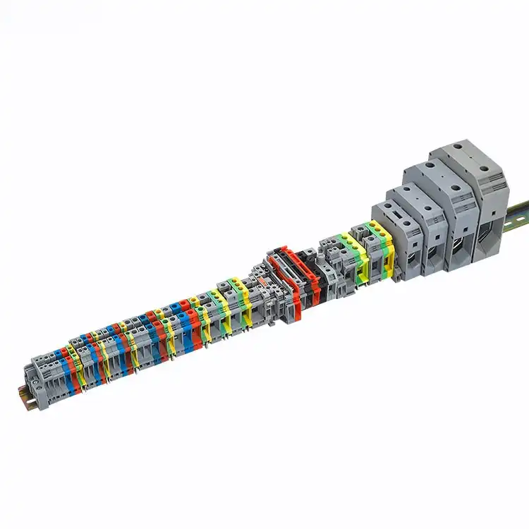
Torque belongs to the part number, not the wire gauge
A screw connection can often be reterminated when all current-carrying and insulating parts remain undamaged. The work still depends on the exact screw thread, clamp design, conductor construction and equipment instructions.
- Use the published tightening value. Do not copy a generic chart or the setting used on a nearby block.
- Prepare the conductor to the stated length. Too little copper can clamp insulation; too much can leave an unsafe exposed section.
- Stop when hardware is damaged. A stripped thread, deformed clamp or pitted current path needs replacement, not extra torque.
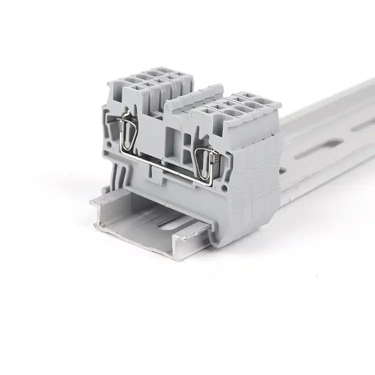
Correct operation replaces the field torque step
Spring technologies maintain contact pressure through their clamping mechanism. The correct action can involve a lever, push button, operating slot or direct push-in, depending on the model and conductor.
- Check the conductor class. Solid, stranded, fine-stranded and ferruled conductors may require different insertion methods.
- Use the intended operating tool. Forcing a screwdriver into the wrong location can damage the spring or housing.
- Do not diagnose “spring fatigue” by feel alone. First rule out wrong size, strip length, ferrule and incomplete insertion.
| Connection | Field torque? | What must be verified | Typical stop condition |
|---|---|---|---|
| Screw clamp | Yes, only when the exact instructions specify it | Model, conductor, strip length, number of conductors, ferrule allowance, torque | Stripped screw/thread, deformed clamp, pitting, cracked or heat-damaged housing |
| Spring cage | No field screw torque on the spring contact | Approved conductor class, actuator, strip length, ferrule and insertion sequence | Mechanical damage or failure to retain a correctly prepared permitted conductor |
| Push-in | No field screw torque on the push-in contact | Which conductors push in directly and which require the clamp to be opened | Broken actuator, damaged entry or lost retention after the correct procedure |

Torque, strip length and ferrules must come from the exact product data
A ferrule can consolidate fine strands, but it is application-specific rather than a universal cure. Some terminals permit bare flexible conductors, some accept ferrules, some reduce the allowed cross-section when a ferrule is used, and some spring terminals are designed for other preparation methods.
- Match conductor material, construction, class and cross-section.
- Match ferrule style, sleeve, barrel length, crimp shape and validated tooling.
- Use aluminum only where the terminal and equipment explicitly permit it.
- Apply joint compound or other preparation only when the manufacturer requires or allows it.
One real product example shows why the data sheet wins
The figures below are published for one Phoenix Contact UT 2,5 screw terminal. They are an illustration of model-specific data, not instructions for a SENTOP product or any other terminal.
| Parameter | Published value for this model | Decision lesson |
|---|---|---|
| Connection method | Screw connection, M3 | Connection structure matters before any service action |
| Tightening torque | 0.5–0.6 Nm | Use only for this identified product and permitted configuration |
| Stripping length | 9 mm | Do not generalize an 8–10 mm rule across terminal families |
| Flexible conductor without ferrule | 0.14–4 mm² | Bare flexible conductors are permitted for this model |
| Flexible conductor with ferrule | 0.14–2.5 mm² | A ferrule changes the permitted range; it is not automatically “better” |
Can you reterminate it, or must the terminal block be replaced?
Retermination is a controlled reuse decision. It is not a way to rehabilitate a current path or insulation system already damaged by heat, arcing, corrosion or mechanical failure.
Retermination may be considered when
All of these conditions can be confirmed under the applicable procedure:
- The exact terminal is identified and current instructions are available.
- The terminal is approved for the conductor material, class, size and quantity.
- The housing, current bar, clamp, screw/thread or spring mechanism is undamaged.
- The conductor can be cut back to clean, undamaged material without creating a length or strain problem.
- The cause—such as poor preparation, strain or an incorrect setting—can be corrected and documented.
Replace the terminal or conductor when
Any of these signs removes confidence in the original connection:
- Charred, melted, bubbled, cracked or distorted insulation or housing.
- Pitting, carbon, severe corrosion or plating damage on the current path.
- Stripped threads, deformed clamp parts, a broken actuator or unreliable retention.
- Heat-damaged insulation, severe oxidation, nicks, broken strands or insufficient remaining conductor length.
- Unknown rating, wrong conductor range, unapproved material or repeated abnormal heating after a documented repair.
Verify the repair before and after controlled re-energization
A neat-looking termination is not the end of the job. Verification covers installation quality, safe restoration of the equipment, operating behavior and a traceable maintenance record.
Visual and installation check
Confirm full insertion, permitted conductor preparation, no unintended exposed copper, correct accessories and labels, secure cable support, restored covers and barriers, and removal of all tools, jumpers, shorts and temporary grounds.
Clear, warn and restore
Follow the established sequence: warn affected people, visually confirm everyone is clear, remove locks and tags only under the procedure, then energize from a safe operating position. Stop if abnormal odor, noise, heat or operation returns.
Compare and trend safely
If the maintenance plan calls for current measurement or thermography, qualified personnel perform it under the approved energized-work procedure at a representative load, comparing like components and recording conditions.
Control the connection across design, installation and maintenance
Repeat failures usually mean the original mechanism was never removed. A durable correction combines compatible parts, controlled workmanship, cable support and condition-based maintenance.
Design for compatibility
Select the terminal for voltage, current, conductor material/class/size, number of wires, environment, mounting, accessories, short-circuit requirements and applicable certification. Use an approved exact replacement whenever the assembly instructions require it.
Control the termination process
Standardize strip-length gauges, conductor preparation, ferrule and crimp-tool combinations, insertion methods and torque-tool control. Add strain relief so cable weight and vibration are not carried by the clamping point.
Maintain by evidence
Set inspection intervals from the exact equipment instructions, criticality, environment, duty and failure history. Some screw and spring terminals are marketed as maintenance-free; do not invent a universal retorque calendar.
Need to replace a damaged terminal block?
Send the information that defines the connection. SENTOP can help identify an appropriate screw, spring or push-in terminal for a new build or replacement review; final installation and safety decisions remain with the qualified designer or installer responsible for the equipment.
- Existing brand and part number
- Terminal and damage photographs
- Conductor material, class and size
- Voltage, current and circuit function
- DIN rail, accessories and environment
- Quantity, destination and certification
Related SENTOP resources
Use the fault guide for diagnosis, the wiring and selection guides for application details, and the product pages when replacement is the correct outcome.
Loose terminal block connection FAQ
Short answers to the repair decisions that most often create repeat failures or unsafe work.
Can I tighten a loose terminal block while it is energized?
No. Do not tighten, release, remove or reterminate a conductor while the terminal is energized. Identify and isolate every applicable source, apply the required lockout/tagout, control stored energy and have a qualified person verify the exposed parts are de-energized before the connection is touched.
What torque should I use on a loose terminal block screw?
Use only the tightening value published for the exact terminal block or equipment assembly and the permitted conductor configuration. Wire gauge alone cannot determine torque. If a defined value must be applied, use a suitable torque tool with a known calibration status and record the data source.
Should every stranded wire use a ferrule?
No. Ferrule use depends on the exact terminal, conductor construction and equipment instructions. Some terminals accept flexible conductors directly, some permit or require ferrules, and a ferrule can change the allowed cross-section. Use a matched ferrule, crimp profile and validated tool only when the product data allows it.
When should I replace the terminal instead of retightening it?
Replace it when the housing is charred, melted, cracked or distorted; the current path is pitted or badly corroded; the screw, thread, clamp, spring or actuator is damaged; or a correctly prepared permitted conductor cannot be retained. Replace heat-damaged or severely nicked conductors as well.
How often should terminal block screws be re-torqued?
There is no universal interval. Follow the exact terminal and equipment instructions plus the site's risk-based electrical maintenance program. Some screw and spring connection systems are described by their manufacturers as maintenance-free, so unnecessary periodic retightening can be the wrong action.
Can thermography prove that a connection is loose?
No. Thermography can screen for abnormal surface heating under a representative load, but overload, imbalance, airflow, ambient conditions and emissivity can produce similar patterns. Qualified personnel should document the load and compare like components, then confirm the cause after safe isolation.
Can electrical tape temporarily fix a loose terminal?
No. Tape does not restore contact pressure, repair a damaged current path or correct conductor preparation. It can hide evidence while heating continues. Restore the connection using the exact product procedure or replace the damaged terminal and conductor.
Official safety and product references
Use the law, standards, adopted editions, equipment documentation and exact manufacturer instructions that apply to the installation in front of you.
- OSHA 29 CFR 1910.333 — Selection and use of work practices — de-energization, lockout/tagout, verification and re-energization requirements for fixed electrical equipment.
- OSHA 29 CFR 1910.334 — Use of equipment — inspection and rating requirements for test instruments, probes and leads.
- OSHA 29 CFR 1910.335 — Safeguards for personnel protection — protective equipment, tools, barriers and alerting techniques.
- OSHA 29 CFR 1910.399 — Definitions — qualified person and other electrical-safety terms.
- IEC 60947-7-1:2025 — Terminal blocks for copper conductors — current IEC product-standard scope for industrial terminal blocks with screw-type or screwless clamping units.
- Phoenix Contact UT 2,5 product data — first-party example of model-specific torque, strip length and conductor ranges.
- WAGO control-cabinet wiring guidance — conductor and operating-method differences for push-in spring connections.
- Weidmüller technical information: ferrules with plastic collars — conductor, ferrule and crimp-quality details.
- Fluke electrical thermography guidance — load, comparison and safety considerations when screening electrical systems.
- NFPA 70B:2026 — Standard for Electrical Equipment Maintenance — electrical maintenance program and condition-assessment context.
