
When to Replace Terminal Blocks in Control Panels: 5 Signs
Replace a control-panel terminal block when heat, electrical discharge, corrosion, mechanical damage or unstable performance has taken the insulation, current path, clamping system or mounting outside a condition that can be restored and verified to the exact product instructions. Age, one color change or one absolute meter reading is not enough by itself.

Replace the block for irreversible condition loss—not simply for age
One decisive defect can be enough: a carbonized barrier, cracked housing, broken rail latch, stripped clamp, eroded contact or chemically damaged current path. Ambiguous evidence such as a hot spot, intermittent input or uniform yellowing calls for controlled investigation first. The exact terminal data and the equipment safety program set the acceptance basis.
Damage cannot be reversed
Char, melt, tracking, cracks, broken mounting, distorted hardware, plating loss or contact erosion means the qualified construction has been compromised.
The symptom is unresolved
Keep the circuit in a controlled condition while qualified personnel compare load, thermal pattern, voltage loss, low resistance and physical evidence.
Condition is verified acceptable
Return to service only when the exact product remains intact, correctly applied and installed, and the abnormal evidence has a supported explanation.
Inspect beyond one block
Check the conductor, ferrule, jumpers, neighboring poles, end stops, rail and enclosure. The visible block may be only one part of the damaged system.
Replacement is hands-on electrical work. Identify every source, de-energize and isolate, apply lockout or tagout as required, control hazardous stored energy, and have a qualified person verify the exposed parts are de-energized. Energized thermography or voltage-drop screening belongs only inside an approved electrical-safety program.
Use a red, amber and green decision—not a two-sign rule
A single severe defect can justify immediate replacement. Two vague symptoms do not automatically prove that replacement is the right correction. Separate conditions that destroy the product's qualified construction from conditions that require more evidence.
| Decision band | As-found evidence | Immediate action | Disposition basis |
|---|---|---|---|
| Red: replace | Char, melt, carbon tracking, deep localized deformation, cracked barriers, broken latch, stripped thread, damaged spring/clamp, contact erosion or plating loss in the current path | Keep isolated; preserve photographs and part identity; inspect the conductor, accessories and adjacent positions | The insulation, current path, clamping mechanism or mounting can no longer be confirmed in its qualified condition |
| Amber: investigate | Localized hot spot, intermittent signal, unexplained voltage loss, conductor movement, surface contamination or color change without confirmed material damage | Control the risk, capture load/context and use the test that can distinguish the plausible mechanisms | Compare exact product data, baseline or like-for-like points before deciding to retain, reterminate or replace |
| Green: retain with record | No cracks, deformation, tracking, contact damage or mounting loss; installation matches instructions; measurements and function are stable under defined conditions | Document the basis, restore covers and update the maintenance record | Condition is acceptable for this product, circuit, environment and maintenance program—not merely because continuity exists |
Decision principle: replacement restores a known component condition; it does not by itself correct an overloaded circuit, wrong conductor, poor strip length, vibration, chemical ingress or a flawed work instruction. Pair the part change with the cause correction.
When to replace terminal blocks in control panels: the five decisive categories
These categories focus on what the product must continue to provide: insulation, a stable current path, controlled clamping, secure mounting and repeatable performance. They apply to screw, spring and push-in designs, but the exact inspection method remains product-specific.
Char, melt, tracking or pitting
Carbonized or melted insulation, branching surface tracks, arc marks, metallic spatter or eroded contact surfaces show that material or geometry has changed. Do not sand, reshape or clean the block back into service. Replace it and determine whether the conductor, ferrule, jumper, neighboring pole or enclosure also received heat or discharge damage.
Cracks, broken barriers or rail retention
A cracked sidewall, broken partition, damaged end plate, failed DIN-rail foot or insecure protective-conductor interface can reduce spacing or allow movement. A block can still pass continuity while its mechanical and insulating functions are no longer dependable. Replace rather than using adhesive, ties or improvised supports.
Stripped threads, distorted clamps or lost retention
Replace when the screw, pressure plate, cage, spring, actuator or conductor stop is visibly damaged or cannot secure an approved conductor using the specified method. Repeated tightening, a wrong tool, side load or an incompatible conductor can change the mechanism. More force is not a repair and movement torque is not proof of original installation quality.
Pitting, plating loss or insulation degradation
Deposits alone require identification; pitting, damaged plating, embrittlement, swelling, stress cracking or a contaminated current path points toward replacement. Preserve the as-found condition, correct the moisture or chemical source, and use only manufacturer-approved cleaning. Abrasive cleaning can remove a qualified contact coating and hide evidence.
Abnormal heat, voltage loss or intermittent function remains
Replacement is justified when repeatable, correctly obtained evidence identifies the terminal as the unresolved weak point and the product cannot be restored and verified by its instructions. Examples include recurring thermal asymmetry under comparable load, unstable low-resistance results or intermittent circuit behavior that follows the connection after conductor and system causes are evaluated.
Uniform yellowing may differ from localized browning, bubbling or warping. Record the pattern and compare the material against product information before declaring failure.
High contact resistance is one possibility; load, conductor size, phase imbalance, ambient heat and external heat sources can overlap.
A damaged or unstable connection may still conduct at the meter's small test current while losing voltage or heating under operating load.
Use measurements to confirm the weak point—not to invent one universal limit
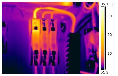
Resistive heating follows the relationship below, which is why a thermal image without current and load context is incomplete. A light-load scan can conceal a developing connection problem, while a heavily loaded but sound conductor may appear warmer than its neighbors.
P = I²R
Electrical loss rises with current squared at constant resistance. The equation does not directly predict terminal temperature because heat transfer, conductor size, enclosure conditions, adjacent loading and duty cycle also matter.
Compare equivalent phases, poles or circuits at a documented operating condition. Record ambient conditions, apparent temperature pattern, current and instrument settings. After corrective work, repeat the same comparison. Fluke's electrical thermography guidance likewise emphasizes load measurement, pattern comparison and baselines.
Thermography and energized voltage-drop measurements expose personnel to an operating electrical system. OSHA 1910.334 states that only qualified persons may perform testing work on electric circuits or equipment. Use the facility's approved work practices, instrument ratings and protective measures; if those controls are not in place, do not improvise the test.
| Evidence method | What it answers | Use it with | Do not assume |
|---|---|---|---|
| De-energized visual inspection | Whether insulation, mounting, conductor preparation or connection hardware is physically damaged | Exact terminal model, labeled photographs, adjacent comparison and product instructions | That every color change represents the same temperature or failure mode |
| Infrared thermography | Where apparent temperature is abnormal under the observed load | Current, ambient, like-for-like points, baseline and repeatable camera settings | That a hot terminal automatically proves a loose screw or requires replacement by itself |
| Energized voltage drop | Voltage loss across defined points at the measured operating current | Authorized energized testing, repeatable probe points and an exact limit, baseline or equivalent comparison | That 10 mV, 50 mV or another single value covers every current and terminal design |
| Four-wire low resistance | Very low resistance while largely excluding test-lead and probe-contact resistance | An isolated test object, understood parallel paths and a manufacturer, baseline or like-for-like criterion | That a generic milliohm limit is a universal terminal-block pass/fail value |
| Continuity or function check | Whether the intended path or function is present at the test moment | Visual/mechanical inspection and the electrical check appropriate to the circuit consequence | That simple continuity proves low resistance, correct polarity, insulation integrity or stable load performance |
For low-resistance testing, Megger explains the four-wire Kelvin method and parallel-path limitation. The method improves measurement quality; it does not supply a universal acceptance number.

Replace the terminal, conductor, accessories—or the affected assembly
The darkest visible spot is not always the full damage boundary. Heat can anneal or oxidize conductor strands, shrink insulation, distort jumpers and transfer into adjacent poles. Chemical ingress can affect an entire rail section. A disciplined scope inspection prevents a new block from being installed onto an already damaged conductor or compromised accessory.
- Conductor: examine strands, insulation, ferrule/crimp, strip length and usable remaining length; remove heat- or corrosion-damaged material by an approved method.
- Terminal: identify the exact catalog number, connection technology, rating, pole function and any internal damage.
- Accessories: inspect jumpers, disconnect knives, fuse carriers, markers, partitions, end plates and end stops for heat, tracking or incompatibility.
- Neighbors: compare both sides of the failed position and expand the boundary if heat, residue or a common installation defect is present.
- Support: confirm rail condition, protective-conductor contact, spacing, enclosure contamination, wire support and strain relief.
Do not batch-replace by habit: one failed block does not automatically condemn a whole DIN-rail row. Replace the larger population when the evidence, product system, obsolescence, shared installation defect or approved repair method supports that boundary.
Identify and tag every conductor before the wiring map changes
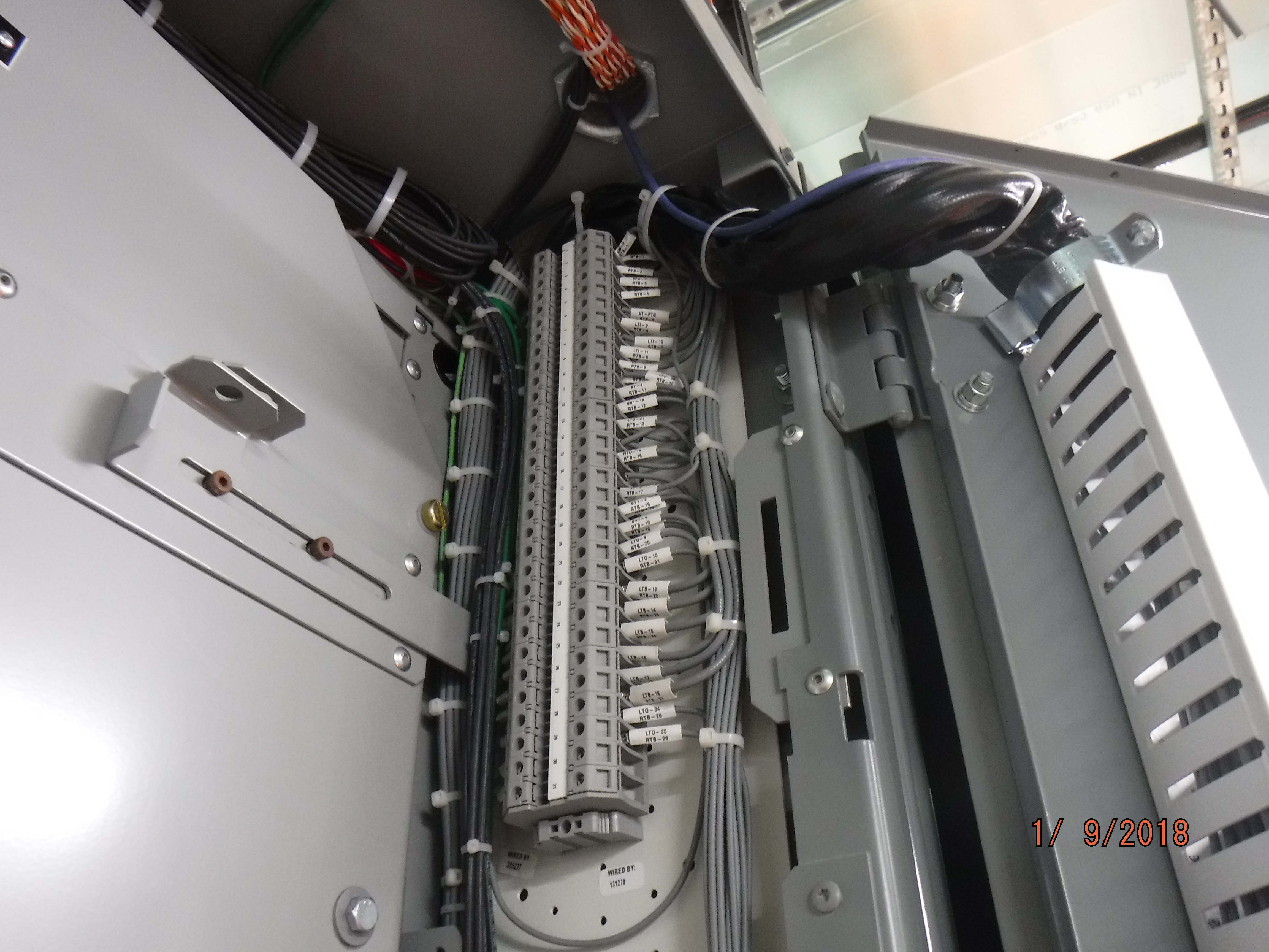
Use the approved schematic and terminal plan, not memory. Photograph overall location, marker strips, jumpers and conductor entry from multiple angles. Record any deviation between the drawing and the as-built panel before disconnecting anything.
Replacement may affect interlocks, protective circuits, shield terminations, commons, jumpers and multiple voltage levels. Define the electrical and functional test plan before the outage so the work does not end with a simple continuity check.
Make the replacement safely—and preserve a verifiable result
This sequence is a planning framework, not a substitute for the equipment procedure, electrical-safety program or qualified-person judgment.
Define the affected circuit and consequence
Identify every source, voltage, stored-energy source, control function, protective function and operating impact. Decide whether removed parts must be retained for warranty, insurance or root-cause review.
Resolve the exact replacement before the outage
Confirm part number, ratings, conductor range, connection method, width, jumpers, markers, end plates, rail interface and certifications. Treat an alternate model as an engineered substitution.
De-energize, isolate and control hazardous energy
Disconnect all electrical sources, address backfeed and stored energy, and apply locks and tags as required. Push buttons, selectors and interlocks are not the sole means of electrical isolation.
Verify the exposed parts are de-energized
A qualified person uses suitable test equipment and the approved verification process, including checks for induced voltage or unrelated backfeed. Until the required steps are complete, treat the parts as energized.
Label, photograph and map before disconnecting
Capture terminal position, conductor markers, polarity, phase, shield/ground paths, jumpers and drawing discrepancies. Keep the as-found evidence associated with the correct asset and circuit.
Remove without transferring damage
Follow the product method for releasing conductors, jumpers and the rail foot. Inspect the exposed conductor, neighboring terminals and rail before installing a new part; do not reuse damaged conductor ends or accessories.
Install to the exact product instructions
Use permitted conductor material, size, strand class, strip length, ferrule and conductor count. Apply the specified actuation or manufacturer-indicated torque with the correct tool and preserve required spacing and wire support.
Inspect, test and control re-energization
Check polarity, jumpers, labels, mounting, conductor seating, covers and tool removal. Perform the approved electrical and functional tests, warn affected personnel, restore energy under the site procedure and capture a new baseline where useful.
Connection technologies and maintenance instructions differ. Some screw designs are described as maintenance-free and spring connections have no conductor screw to torque. Do not disturb a healthy new connection after energization unless the exact product or equipment procedure requires it.
Physical fit is not equivalence—match the complete application
The replacement must work as part of the evaluated panel and terminal system. A block that clips to the same 35 mm rail can still differ in electrical rating, conductor capability, connection geometry, spacing, accessory system and approval.
| Requirement | Confirm before ordering | Why it matters |
|---|---|---|
| Exact identity | Manufacturer, series, catalog number, revision, function, color and approved substitution status | Series determine geometry, accessories, test basis and installation instructions |
| Electrical ratings | Applicable voltage/current ratings, circuit category, conductor temperature basis, short-circuit or coordination data where required | Nameplate values depend on the certification system, application and conductor |
| Conductor system | Copper/aluminum permission, solid/stranded class, AWG or mm² range, ferrule use, strip length and allowed conductor count | A physically insertable conductor may still be outside the evaluated range or preparation |
| Connection technology | Screw, spring, push-in or bolt connection; required tool, actuation and torque where applicable | Installation, inspection and maintenance requirements are design-specific |
| Mechanical system | Rail/profile, width, height, conductor direction, end stops, partitions, jumpers, markers and touch-safe covers | Accessory mismatch can defeat spacing, identification or current distribution |
| Environment | Ambient temperature, grouping/derating, enclosure, pollution, moisture, vibration, chemicals and required material compatibility | The root cause may recur if the new product faces the same unsuitable environment |
| Special function | Protective conductor, fuse, disconnect/test, sensor/actuator, intrinsically safe or safety-circuit requirements | Color or shape alone does not establish the required protective or functional performance |
Procurement shortcut: send the old part number, clear front/side/top photos, dimensions, conductor information, ratings, accessories, panel drawing and certification market. SENTOP can help review a replacement direction, but the equipment owner remains responsible for the final engineered substitution and safety approval.
Prove the panel is ready—do not stop at continuity
The test package should match the circuit consequence and the original symptom. A failed analog signal, a protective-conductor terminal and a power feeder do not share one universal test. Use the equipment procedure, product data and applicable standard to define acceptance.
Visual construction
Correct model, pole, color/function, end plates, jumpers, markers, covers, spacing, rail retention and no trapped or exposed strands.
Conductor preparation
Correct material, size, strip length, ferrule if permitted, full insertion, approved conductor count and supported routing without contact-point strain.
Connection method
Specified actuation or indicated torque, correct tool and bit, intact hardware and required record. Do not infer quality from movement torque after the fact.
Electrical tests
Polarity, protective continuity, low resistance, insulation or voltage-drop checks only as authorized and with product/system-specific criteria.
Functional proof
Confirm the actual I/O, interlock, indication, disconnect, fuse, safety or power function through the approved commissioning or maintenance test.
Comparable-load baseline
Where justified, record current, operating condition and a new thermal/electrical baseline after safe restoration so future trend data has context.
Cause correction
Document conductor, load, environment, vibration, enclosure, tooling, training or work-instruction actions that prevent the same mechanism recurring.
Traceability
Record removed and new part numbers, date, personnel, measurements, photos, drawing/BOM updates and retained evidence disposition.
Release approval
Use the facility's formal return-to-service process, warn affected personnel and confirm tools, temporary jumpers, grounds and foreign material are removed.
For deeper mechanism and root-cause work, use SENTOP's terminal block failure analysis guide. It separates the observed failure mode from the mechanism, contributing causes and verification evidence.
Use the right document for the right decision
Workplace rules govern how personnel interact with the equipment. Product standards describe evaluated terminal-block characteristics. Manufacturer instructions control the exact installation. None of these should be converted into a made-up universal field alarm threshold.
OSHA 1910.333
OSHA's electrical work-practice rule addresses de-energization, lockout/tagout and qualified-person verification before exposed parts are treated as de-energized. Apply local law outside its jurisdiction.
UL 1059
UL Solutions identifies UL 1059 among standards used to evaluate terminal blocks. Confirm the exact recognized/listed component conditions and end-product application.
IEC 60947-7-1:2025
IEC 60947-7-1:2025 specifies requirements for terminal blocks for copper conductors within its scope. Type-test conditions are not automatic field replacement limits.
Manufacturer instructions
Use the current catalog number data for conductor preparation, torque or actuation, mounting, accessories and maintenance. The SENTOP torque guide explains how to resolve product-level values without relying on AWG averages.
Maintenance interval: risk, equipment consequence, environment, history, adopted maintenance program and manufacturer guidance determine inspection frequency. Do not publish annual, six-month or quarterly terminal replacement/scan intervals as universal rules.
Send the old part, application and damage evidence—not only a rough dimension
SENTOP can review terminal-block categories, part matching and project supply requirements for control-panel replacement work. Final engineering equivalence, installation, electrical-safety and return-to-service decisions remain with the qualified personnel responsible for the equipment.
- Manufacturer, series, catalog number and clear part photos
- Terminal function, pole count, rail/mounting and accessories
- Conductor material, AWG or mm², strand class and ferrule
- Circuit voltage, normal/peak current and certification market
- Enclosure, ambient, vibration, moisture or chemical exposure
- As-found damage, quantity, drawing/BOM and project timeline
Related terminal block resources
Use these guides to investigate the failure, resolve exact installation data and control the new connection.
Terminal block replacement questions
These answers deliberately avoid generic age, temperature, voltage-drop and re-torque rules. The exact product, circuit, adopted maintenance program and safety procedure control the work.
How do I know when a terminal block must be replaced?
Replace a terminal block when inspection shows irreversible loss of insulation, current-path, clamping or mounting integrity. Examples include carbonization, melting, tracking, cracks through a barrier, a broken DIN-rail latch, stripped threads, a distorted clamp, contact erosion or corrosion that has damaged the qualified surface. Persistent abnormal heat, voltage loss or intermittent behavior also supports replacement when the exact product procedure cannot restore and verify a known acceptable condition.
Does discoloration always mean a terminal block should be replaced?
No. Uniform color change can come from age, light or the surrounding environment, while localized browning near one conductor entry is more consistent with a local heat source. Record the pattern, load, adjacent comparison and housing condition. Replace when discoloration is accompanied by charring, melting, distortion, brittleness, tracking or other evidence that insulation integrity has been lost; otherwise investigate against the exact product limits rather than using color alone.
Can I fix a hot terminal block by tightening the screw?
Do not use tightening as the first diagnostic step. It changes the as-found condition and can further damage a stripped thread, clamp or conductor. Record the thermal pattern and load, make the equipment safe, identify the exact terminal, and inspect the conductor and connection mechanism. If the component or conductor is heat damaged, replace or reterminate it as required and verify the result under comparable conditions.
What voltage drop, resistance or temperature means replacement?
There is no universal millivolt, milliohm or temperature value for every terminal block. The result depends on the model, conductor, current, test points, ambient conditions, parallel paths and measurement method. Use an exact manufacturer limit when available, a commissioning baseline or equivalent connections under the same conditions. A trend or anomaly can trigger investigation, but disposition should be tied to product-specific evidence.
Should I replace the entire DIN-rail row when one terminal fails?
Not automatically. Inspect adjacent terminals, jumpers, end stops, markers, conductors and the rail for transferred heat, tracking, contamination or mechanical damage. A larger replacement scope is justified when damage has spread, the same installation defect affects multiple positions, the series is obsolete, accessories cannot be restored correctly or the approved repair requires a coordinated assembly change. Record why the chosen boundary is sufficient.
Can I replace a terminal block with a different brand?
A common DIN-rail profile does not make two products electrically or mechanically equivalent. Confirm ratings, conductor range and type, connection method, width, clearances, jumper system, end plates, markers, mounting, environmental suitability and required certifications. Protective-conductor and safety-related terminals need particular care. Treat a cross-brand change as an engineered substitution, not a visual match.
How old is too old for a terminal block?
Calendar age alone is not a universal replacement criterion. Service life depends on loading, temperature, vibration, moisture, chemicals, conductor preparation, installation quality and product design. Use condition, history, manufacturer guidance and risk to set inspection and replacement decisions. Age becomes more important when documentation is missing, the product is obsolete or compatible replacement accessories are no longer available.
Who should replace terminal blocks in a control panel?
The work should be planned and performed by personnel qualified for the equipment and electrical hazards under the facility's safety program and applicable law. Hands-on replacement begins only after all sources are identified, the circuit is de-energized and isolated, lockout or tagout is applied as required, hazardous stored energy is controlled, and the exposed parts are verified de-energized with suitable test equipment.
Technical references
Use the current adopted edition, exact equipment documentation and local safety program. The links below support the decision boundaries; they do not replace site-specific engineering judgment.
- OSHA 29 CFR 1910.333 — electrical work practices, de-energization, lockout/tagout and qualified-person verification.
- OSHA 29 CFR 1910.334 — qualified persons and test-instrument requirements for electrical testing work.
- OSHA 29 CFR 1910.147 — control of hazardous energy for servicing and maintenance.
- UL Solutions connector certification — terminal-block standards including UL 1059.
- IEC 60947-7-1:2025 — official scope for terminal blocks for copper conductors.
- Fluke electrical thermography guidance — load, comparison, baseline and thermal-pattern interpretation.
- Megger four-wire resistance guidance — Kelvin measurement and parallel-path considerations.
- Phoenix Contact screw connection — an example of a product-specific maintenance-free screw design that does not require retightening.
- NFPA 70B, 2026 edition page — electrical equipment maintenance program context; apply the edition adopted by the facility and jurisdiction.
- Schneider Electric maintenance example — product-specific visual inspection and avoidance of unnecessary connection disturbance.
External images are licensed for reuse as credited. For production performance and URL control, download, optimize and self-host copies in the SENTOP WordPress media library while preserving creator and license attribution.
