
Present design
Positions occupied by the released current design, excluding spare positions.
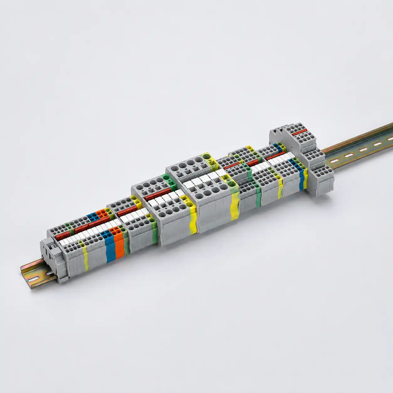
There is no universal spare-terminal percentage. Apply mandatory safety and certification requirements first, then the owner or contract commitment. When those documents are silent, calculate current demand, named future circuits, and generic contingency separately for each electrically interchangeable terminal family—and verify the physical wiring path, accessories, labels, and panel evidence.
Applicable law, the authority having jurisdiction, the governing panel, machine, or assembly requirements, product certification conditions, and manufacturer instructions come first. The owner or contract specification then controls the spare-capacity commitment where it adds requirements. A contract percentage cannot authorize a configuration that conflicts with mandatory safety requirements or the evaluated panel design.
If no document sets the quantity, do not default to “10%” or “20%.” Divide the terminal schedule into genuinely interchangeable families. Count the positions occupied by the released design, add the actual positions required by approved future circuits, and then add a separately approved generic contingency. Finally, prove that rail, accessories, duct, cable entry, labels, protection, thermal conditions, and documentation can support the addition.
The result is not one percentage. It is a schedule that states exactly which positions are fitted, electrically connected, mechanically reserved, or held as shelf stock—and what each position can eventually serve.
Published percentages are project examples, not industry law. One public water-project specification requires 10% spare terminal and fuse blocks with stated minimum quantities; a Western Australia UPS specification uses a 20% allowance. Those clauses govern their projects only.
Define the reserve class before counting. Otherwise the panel shop, commissioning team, and owner can all report the same quantity while describing different physical and electrical resources.
| Reserve class | What it means | Electrical-state rule | What must be included |
|---|---|---|---|
| Installed spare terminal | A fitted, uniquely identified position not assigned to a released field circuit. | Record whether it is isolated or connected. The SPARE marker does not prove absence of voltage. | Exact terminal, marker, rail length, end hardware, approved accessories, schedule and BOM entry. |
| Wired or energized reserve | A fitted position intentionally connected to a common potential, jumper, internal conductor, or approved future circuit path. | Identify it as electrically connected and protect it as required; never present it as an isolated unused point. | Potential, protection, commoning, conductor, guarding, label, drawing, and test status. |
| Reserved rail or enclosure space | Documented physical room for future components. | No termination capacity exists yet. | Rail, required internal electrical spacing, wiring room, operating clearance, service access, duct, cable entry, and compatible end hardware. |
| Unused level or connection | An unused connection on a multi-level or multi-wire product. | Count only when the exact product, circuit arrangement, ratings, segregation, identification, and access allow the intended use. | Level/connection identifier, conductor-per-clamp limits, accessories, schedule mapping, and approval record. |
| Spare PLC or remote I/O | An unused control-system channel. | It is not terminal capacity and may still need interface power, protection, isolation, and field wiring. | I/O assignment, power budget, interface hardware, terminal path, cable entry, and software/configuration records. |
| Shelf stock | Blocks and accessories held outside the panel. | It provides replacement inventory—not installed connection space or an approved future circuit. | Exact order numbers, storage conditions, compatibility/revision control, and replenishment policy. |
Installed is not automatically better. Fitted and labeled spares can reduce future installation work when the exact family and expected use are known. Empty rail or enclosure space can be more appropriate when future ratings, conductors, protection, thermal loading, or certification details remain unknown.
This is a transparent planning aid—not a formula from IEC, UL, NFPA, OSHA, or a terminal-block manufacturer.
Positions occupied by the released current design, excluding spare positions.
Actual terminal positions required by approved future circuits not already in B; count positions—not devices.
The counting basis named by the governing requirement: blocks, levels, or usable positions within one family.
The approved project contingency factor for this family—not a universal industry percentage.
A documented minimum that prevents a small terminal family from rounding to no usable reserve.
The greater of the approved minimum or the percentage-derived quantity after the documented rounding rule.
Current positions plus named future positions plus generic contingency for the interchangeable family.
Do not double-count or undercount. If approved future circuits are already in the released design, include them in B and set F to zero. Add a separate commissioning allowance only when it is explicitly approved, stated in terminal positions, and not already covered by F, p, or M. Use upward rounding only when the contract requires it or the design basis adopts it.
Apply the planning model only to positions that are genuinely interchangeable by function, potential, voltage/current rating, conductor range and construction, certification, geometry, and required accessories. A gray feed-through block, a PE terminal, a fused disconnect, and a shield connection do not become one family because they sit on the same rail.
Define whether each count means a physical housing, a terminal level, a clamping point, or a usable terminal position. Multi-level and multi-wire products can make those units different. The terminal schedule, BOM, panel layout, RFQ, and FAT record must use the same unit.
Percentage denominator: state whether the project applies its percentage to current occupied positions, total fitted positions, each family, or another explicit base. Do not silently include existing spares in the denominator and create a compounding count.

Each family below can require a different combination of installed capacity, named future circuits, reserved space, and certification review.
Suitable for a documented generic reserve when future sensors, solenoids, or interlocks are credible. Coordinate terminal positions with I/O channels, commoning, conductor range, and power-supply capacity.
Reserve the required signal positions plus shield treatment, isolator, fuse, and routing where applicable. One “future transmitter” may require several terminal positions.
Use a terminal intended for PE/PEN duty and verify the rail/bonding arrangement. Never relabel an ordinary feed-through position as PE.
Reserve only when the future circuit concept and protection or test function are known. A feed-through spare cannot replace a fuse, disconnecting, or testing function.
When load and conductor data remain unknown, reserve enclosure, rail, duct, and cable-entry space instead of installing a guessed terminal. Recheck heat, bend space, protection, and fault duty.
Use only project-specific provisions that preserve segregation, certification, functional-safety assumptions, and the approved risk assessment. Do not apply a generic control-terminal percentage.
Power and high-current future circuits can change conductor bend space, terminal temperature rise, protective-device coordination, available fault-current evidence, bus or jumper loading, ventilation, enclosure layout, and short-circuit withstand or SCCR documentation. The terminal count is only one part of that review.
If a future motor, heater, or feeder is commercially likely but its load, cable, protection, and market requirements are not released, document engineered mechanical space and a design hold point. Installing a guessed high-current terminal can lock the panel into the wrong conductor range or certification path.

Public project documents prove that different spare policies exist. They do not establish what every panel should use.
City of Thornton Project No. 19-37 requires 10% spare terminal and fuse blocks, subject to minimum counts of 20 terminal blocks and 6 fuse blocks, with labeling. The clause belongs to that project specification.
Main Roads Western Australia Specification 713 for UPS equipment uses a minimum 20% allowance of spare terminals unless otherwise specified. It is not a general control-panel code rule.
Do not average unrelated specifications. When a customer document states a percentage, clarify its denominator, terminal-family scope, minimum count, rounding convention, labeling, and whether it requires fitted terminals or reserved space. When documents are silent, use the family assessment—not a percentage selected because it appears familiar.
A future connection needs more than millimeters of rail. Confirm that the planned family remains available and compatible, and that the enclosure has the internal spacing, end stops, end or intermediate plates, partitions, markers, duct capacity, cable-entry area, bend room, operating clearance, and service access required by the future configuration.
Place installed spares near the related family when that helps routing and troubleshooting, while maintaining required separation between potentials and circuit types. If every spare is placed at one rail end, verify that a future conductor can reach it without crossing protected boundaries or blocking labels and accessories.

Before a spare can become an approved circuit, every downstream and upstream dependency must be released.
Gland, connector, shield, bend radius, route, and enclosure environmental integrity.
Fill, separation, heat, access, conductor length, and path to the intended terminal.
Function, rating, conductor, clamp count, accessories, electrical state, and marking.
Fuse, breaker, disconnect, relay, isolator, commoning, PE, or shield treatment.
I/O channel, power-supply loading, logic, relay capacity, and system integration.
Drawing, BOM, label, test, SCCR or withstand, certification, and as-built change.
This composite example demonstrates the method. It is not a standard, customer case, or recommended universal ratio.
| Family | Released and future demand | Planning result | Required coordination |
|---|---|---|---|
| 24 VDC discrete | B = 32 occupied positions; project p = 10%; M = 2; no named future positions. | With an explicitly adopted upward-rounding rule, R = max(2, ceil[3.2]) = 4; T = 36. | Confirm compatible spare I/O and power capacity, or label the reserve as terminal-only. |
| Analog / shield | B = 4. One approved future transmitter requires two signal positions plus one documented shield path. | F equals the actual required positions, not “one device.” Add generic R only if the design basis requires it in addition to F. | Coordinate isolator, fuse, shield treatment, routing, and PLC/remote-I/O capacity. |
| PE | B = 3. One likely additional field cable has been approved as a named future. | Provide one like-for-like PE position only after grounding and route review. | Verify the exact PE terminal, rail/profile, bonding path, conductor, and applicable standard. |
| Fuse / disconnect | No released future protected circuit. | Do not copy the feed-through reserve factor automatically. | Document rail/enclosure space if later protection engineering is expected. |
| Power | One future motor is commercially possible, but load, cable, and protection data are not released. | Reserve engineered enclosure, rail, duct, and cable-entry space; hold terminal selection. | Release only after current, conductor, protection, thermal, SCCR/withstand, and certification review. |
The auditable output is the schedule—not the grand total. A technician should be able to identify which positions are immediately usable, which are electrically connected, which require another device or engineering study, and which are mechanical space only.
Use SENTOP's Terminal Strip & Rail Length Planner only as a layout estimate; the released family counts, accessories, ratings, and certification evidence still come from the engineering record.
Identify law, AHJ requirements, panel/machine or assembly standard, product certification conditions, manufacturer instructions, contract clauses, owner standards, hazardous-area rules, and the panel specification.
Divide positions into electrically interchangeable families and define the counting unit—housing, level, clamping point, or usable position.
Translate each named future service into actual terminal positions, cable entry, conductor, I/O, interface, protection, PE/shield, segregation, and power needs.
Record D, p, M, and the rounding rule for every family. Do not hide the policy in an engineer's memory or a generic note.
Keep present design, named future positions, and generic contingency separate. State whether future demand can satisfy the generic quota.
Add exact terminal and accessory order numbers; confirm rail, end hardware, partitions, duct, cable entry, internal spacing, access, markers, and electrical state.
Align schematic, terminal plan, panel layout, BOM, jumper/commoning data, marker file, I/O list, procurement description, test plan, and certification evidence.
Verify count and usability during FAT, resolve exceptions, and provide the approved as-built terminal export and change-control rules to the owner.
Assign every fitted or reserved position a unique strip ID, terminal designation, functional family, exact catalog number, reserve class, electrical state, marker text, associated future circuit where known, and drawing/BOM reference. Use the same identifiers in the terminal schedule, schematic, panel layout, marker file, FAT record, and as-built export.
Verify fitted positions, connected reserves, unused approved levels, rail-space reserve, and shelf stock separately.
Match function, potential, product family, order number, level, electrical state, and marker.
Confirm end hardware, duct, cable path, access, separation, and room for the intended conductor and accessory.
For named futures, confirm I/O, protection, interface, power, grounding/shielding, and cable entry.
Check applicable panel/assembly standard, certification conditions, SCCR/withstand implications, and change-review responsibility.
Freeze the released drawing, BOM, terminal export, label data, FAT result, and approved deviations at one revision.
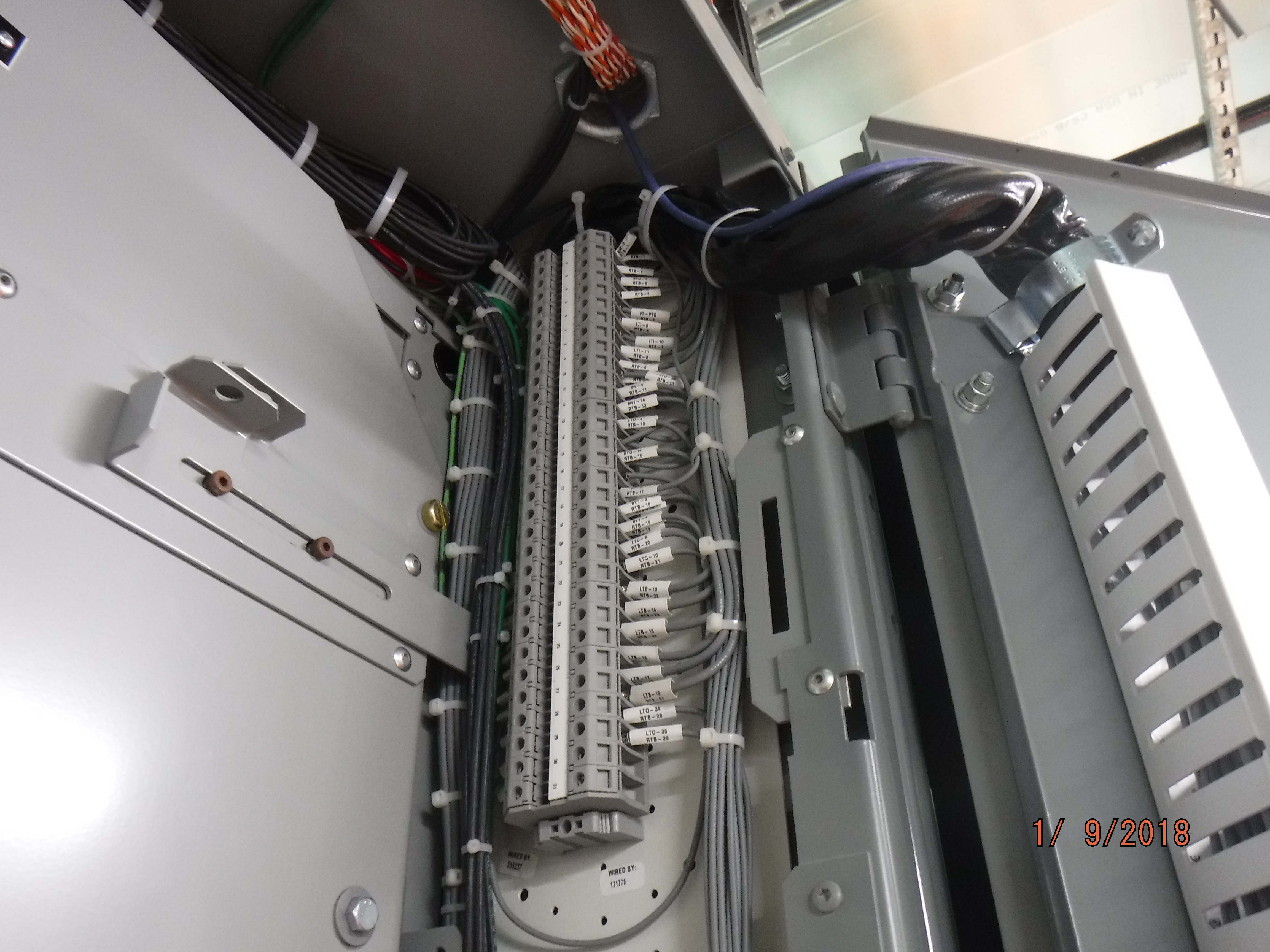
A label or empty-looking clamp is not evidence that the position is isolated, suitable, or safe to touch.
Identify every normal, alternate, stored-energy, and backfeed source. Follow the site's energy-control procedure, de-energize and lock or tag where required, and verify absence of voltage with suitable test equipment.
Check conductor, strip length and torque where applicable, jumpers, PE/shield treatment, protection, I/O and relay capacity, power supply, segregation, fault duty, temperature, entry, duct, environment, and certification.
“SPARE” never means “dead.” The position can be energized through a jumper, common potential, internal conductor, or backfeed. Use the drawings and qualified verification—not marker text—to establish electrical state. Update the schematic, terminal plan, BOM, labels, test record, and as-built package before energization.
A certified terminal block does not certify the future circuit or completed panel. Recheck the applicable panel or machine standard, the terminal's exact certification and instructions, conductor and accessory limits, protection, SCCR or short-circuit withstand method, temperature rise, spacing, and enclosure conditions. A field modification can affect an existing certification and may require manufacturer, NRTL, or AHJ review.
It hides shortages in PE, signal, fused, safety, and high-current functions. Segment the schedule by interchangeable family.
A future device can need several positions and accessories. Count its actual path separately unless the contract explicitly treats it as quota fulfillment.
A free channel does not provide a terminal, marker, cable route, protection, isolation, interface, or power budget.
Rail space can be useful, but it is a different resource with its own accessory, duct, entry, spacing, and compatibility review.
A marker cannot prove electrical state. Record commoning, internal wiring, potential, and protection separately.
Maintenance cannot distinguish a deliberate spare from an abandoned wire or incomplete design. Assign a unique designation and record.
Protection, separation, thermal duty, fault evidence, certification, and risk controls can make the generic percentage invalid.
Duct fill, cable entry, bend room, marker visibility, end parts, or service access can make nominal capacity impractical.
Send the inputs below so the terminal schedule, BOM, layout, labels, and FAT criteria describe the same capacity.
For a structured vendor handoff, use the terminal block RFQ checklist.
No. Some owner or project specifications require 20%, while other specifications use 10% plus minimum quantities or another rule. These are project requirements, not universal code provisions. Apply mandatory safety and certification requirements first, then the governing contract; when documents are silent, use a documented family-by-family assessment.
It can be enough for a stable, well-defined family when the owner accepts it, the denominator and rounding rule are clear, and a minimum prevents the count from disappearing. It can be inadequate for a small signal or PE group, named future circuits, or additions that need I/O, protection, shielding, segregation, or extra terminal positions.
Neither is universally preferable. Installed and labeled spares can reduce later work when the exact family and use are known. Reserved rail or enclosure space can be better when future current, conductor, protection, heat, or certification details remain unknown. Record and inspect the two resources separately.
No. A spare PLC or remote-I/O channel is control-system capacity. It does not provide a compatible terminal, marker, cable route, fuse, isolator, relay, power budget, or protective arrangement. Plan I/O and terminal reserves together, but report them separately.
Only when the exact product configuration, circuit function, voltage/current rating, conductor limits, separation, identification, accessories, and physical access permit the intended use. Record the exact level or connection in the terminal schedule; an empty opening is not automatic spare capacity.
Usually they should be planned as separate functional families because their duties, accessories, protection, grounding, test functions, and safety implications differ. If a project specification groups them, follow its wording and clarify the count; otherwise do not let one grand total hide a functional shortage.
Use a unique terminal designation plus a project-approved reserve status. Record the strip ID, family, exact product, level or position, electrical state, marker text, and drawing/BOM reference. The schematic, terminal plan, layout, marker file, FAT record, and as-built export should agree.
No. A spare position can be connected through a jumper, common potential, internal conductor, or backfeed. The marker describes design status, not an electrically safe work condition. Qualified personnel must use the drawings, energy-control procedure, and suitable test equipment to establish electrical state.
Verify count by family, designation, exact catalog product, reserve class, electrical state, accessories, rail/duct/cable-entry capacity, physical access, separation, and drawing/BOM consistency. For a named future circuit, check the complete path including I/O, interface, protection, power, grounding/shielding, and certification implications.
No. The B/F/R/T model is a transparent planning aid. IEC, UL, NFPA, OSHA, Autodesk, and terminal manufacturers do not impose this formula. Use the method only when it aligns with the governing documents, define every term and rounding rule, and have the responsible engineering team approve the design basis.
Use the latest exact product data, locally adopted requirements, and project documents for every released panel.



_(25780525148).jpg)