Core Products: Terminal Blocks, Transfer Switches & Digital Panel Meters Supporting Electrical Categories | OEM/ODM | Project-Based Quotation
Products
Industries
Resources
Electrical Tools
Company
Start a Conversation
Share a model, BOM, product photo or application requirement for review.
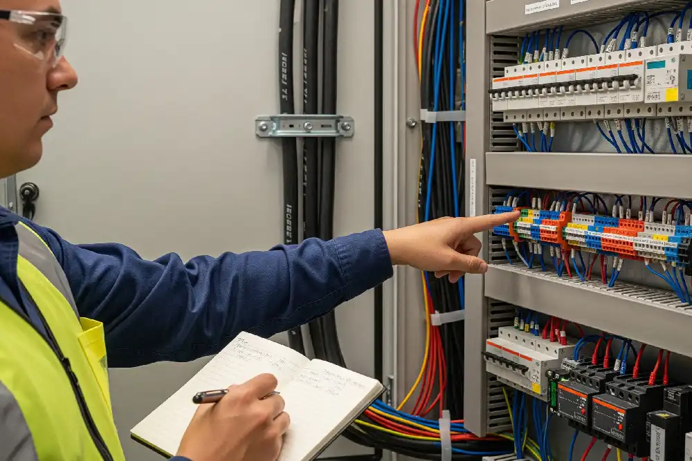
Technician reviewing terminal blocks and wiring inside an electrical control cabinet
Home/Blog/Customized terminal blocks
OEM Connection Engineering • Selection Guide For Panel Builders, Equipment OEMs, Electrical Engineers, and Technical Buyers

Why Choose Customized Terminal Blocks for Unique Electrical Needs?

Choose customization when a standard part creates a measurable engineering, assembly, identification, space, interface, compliance, or service problem. Start with configured catalog parts or a preassembled rail; commission a new terminal design only when proven systems cannot meet the verified requirement.

Customize the smallest layerMarkers, accessories, rail assembly, PCB interface, then new geometry
Configuration is not a new ratingEvery exact part and the finished assembly still need verification
Judge total installed costInclude engineering, wiring, inspection, rework, and service
Release controlled evidenceFreeze the drawing, BOM, jumper map, marker file, and revision

Image: SENTOP article media. Shown for connection-planning context; the visible equipment does not establish a product rating or project approval.

Direct answer

When do customized terminal blocks make sense?

They make sense when the same documented problem will repeat across a panel, machine, PCB, production batch, or service lifecycle. The solution may be as modest as preprinted markers and approved jumpers, or as comprehensive as a fully assembled, inspected, and revision-controlled DIN rail. It does not automatically mean a new molded housing or current-carrying metal part.

First test the requirement against a proven terminal-block and accessory system. If compatible catalog parts solve the circuit and mechanical constraints, configure those parts. Escalate to engineered geometry only when the catalog search and interface review show a genuine gap.

Level 1 · Lowest change

Configured catalog terminal

Typical scope: approved marker text, color option, jumper, coding element, separator, test accessory, or compatible mounting part. Best for repeat panels where the electrical interface already fits. Release exact order numbers and accessory relationships.

Level 2 · Assembly service

Preassembled terminal rail

Typical scope: rail length, terminal order, end stops, bridges, covers, markers, test points, and documented inspection. Best when repeated manual assembly causes mistakes or consumes labor. Control the complete rail BOM and drawing.

Level 3 · Product configuration

Configured PCB connection

Typical scope: pole count, pitch, color, actuation, coding, marking, solder-pin arrangement, and wire-entry direction within a supported family. Verify the PCB footprint, mating part, enclosure clearance, conductor, and lifecycle.

Level 4 · Highest change

Engineered custom solution

Typical scope: new geometry, interface, housing, material, mounting, or integrated function. Use only when lower levels fail. New current paths or insulation geometry require a defined design-verification, tooling, qualification, approval, and change-control program.

01 · ProblemDefine a measurable constraintState circuit, conductor, space, environment, service, volume, and target market.
02 · SearchExhaust proven systems firstCheck catalog functions, multilevel options, accessories, and configured assemblies.
03 · ConfigureFreeze the smallest controlled changeTranslate the requirement into exact parts, drawing, markers, and acceptance criteria.
04 · ValidatePilot, approve, and releaseConfirm electrical, mechanical, compliance, production, and service evidence.
Catalog first

Standard, configured, or fully engineered?

A standard solution is usually better when it already meets function, conductor, ratings, insulation coordination, mounting, accessories, approvals, and service needs. Familiar parts simplify sourcing, spares, training, and documentation.

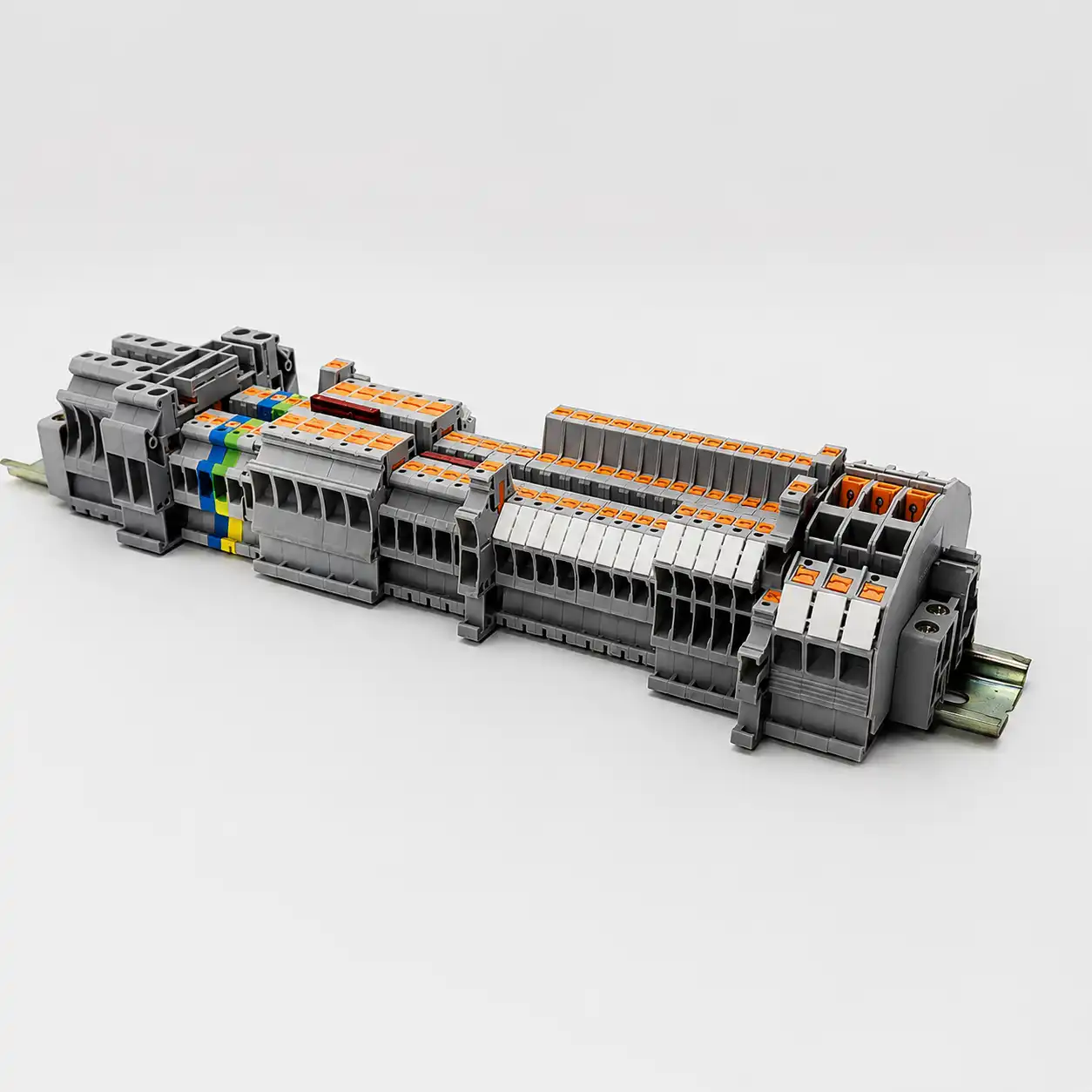
SENTOP DIN rail terminal blocks in multiple sizes and functions mounted on one rail
Start with a proven modular terminal family. Image: SENTOP DIN rail terminal blocks. Confirm the exact terminal, function, accessory relationship, rating, and availability before configuration release.
What “standard enough” looks like

Do not customize for appearance alone

Color consistency or a preference for a unique shape rarely justifies new engineering by itself. Customize when the present arrangement creates recurring waste or risk—misidentification, incorrect jumper placement, rail-length errors, slow testing, an unusable cable-entry angle, a PCB mismatch, or poor traceability.

Use a structured terminal-block selection guide before deciding that the catalog has failed. Then compare unit cost with engineering time, wiring labor, inspection, rework, field troubleshooting, spares, and revision management.

Stay standard

The exact model and its native accessories meet every documented requirement with acceptable assembly effort.

Configure the assembly

Proven components fit, but their sequence, marking, bridging, rail, packaging, or documentation must repeat reliably.

Configure the product family

A supported combination of poles, pitch, coding, color, actuation, or pin layout is needed for an OEM interface.

Engineer a new solution

No supported catalog or configured family meets the verified electrical, mechanical, environmental, or interface requirement.

Decision levelWhat changesBest-fit triggerMinimum release evidence
Standard catalog partNo supplier modification; use the published terminal and supported accessories.Application fits without recurring assembly, identification, space, or interface loss.Exact order number, current data sheet, certificates in scope, accessory list, and installation requirements.
Configured catalog systemMarkers, approved colors, bridges, coding, separators, covers, or function sequence.The core terminal is correct but the repeatable use needs error-proofing or clearer identification.Released configuration list, marker file, jumper map, compatibility evidence, and visual acceptance sample.
Preassembled terminal railRail cut, mounted sequence, end parts, functional accessories, marking, packing, and inspection.Repeated panel builds lose time or quality during manual rail assembly.Rail drawing, complete BOM, dimensions, terminal schedule, inspection plan, revision, and approved pilot.
Engineered custom productNew current path, housing, material, geometry, interface, mounting, or integrated function.Verified requirements cannot be met by supported parts or configurations.Design inputs, risk review, drawings, test plan/results, tooling control, compliance path, samples, and formal change control.

Quantity influences tooling economics, but volume alone does not prove a technical need. A well-controlled configuration can start with low quantities; a new design may still be unjustified at high volume if a standard system already works.

Six value cases

Where customization creates measurable value

Tie each proposed change to a failure mode, time loss, interface mismatch, or compliance requirement. If the team cannot define the benefit and its acceptance evidence, the customization brief is not ready.

01 · Error proofing

Identification that follows the drawing

Preprinted terminal IDs, wire markers, group labels, approved colors, coding, and separators can reduce position errors. Release the marker source file and confirm material, print durability, required symbols, and the exact hardware function. Review terminal-block accessories as system parts, not decoration.

02 · Repeat production

Ready-to-install rail assemblies

A preassembled, fully marked rail can move cutting, terminal order, end parts, jumpers, and inspection into a controlled upstream process. It is valuable when the same panel repeats and manual rail building causes variation. The panel-builder application path helps frame complete installed cost and production needs.

03 · Space and service

Layout optimized around real access

Compact, multilevel, angled-entry, or function-integrated blocks may reduce rail length, but density is not the only target. Preserve conductor bend space, tool access, heat paths, markers, test access, creepage and clearance, and replacement room. Compare the layout against the verified essential terminal-block specifications.

04 · Mixed functions

One documented field interface

A terminal strip can combine feed-through, PE, neutral, fuse, disconnect, test, distribution, and signal functions. The sequence may be customized, but each position retains its own purpose, ratings, protection context, and operating limits. Select bridges and other parts through the verified terminal-block accessories guide.

05 · Unique PCB interface

Poles, pitch, coding, and pin layout

Configured PCB terminals or plug/header systems can align field wiring with the board, enclosure, and production flow. Pole count and pitch are only the start: verify solder footprint, orientation, mating family, polarization, locking, conductor preparation, service clearance, and lifecycle before the PCB is released.

06 · Environment and market

Evidence matched to the installation

Temperature, enclosure, pollution, condensation, vibration, chemicals, altitude, corrosion, and target-market rules can drive material, spacing, mounting, and accessory choices. Use the exact configuration to review pollution degree and approval scope; do not transfer a family logo to every variant.

The compliance boundary

Do not customize away the evidence

A new label, rail sequence, housing color, or assembly service does not automatically change electrical performance—but it also does not prove that every original rating applies to the finished configuration. The current path, insulation system, conductor, jumper, adjacent potentials, enclosure, ambient conditions, mounting, and end-product method all matter.

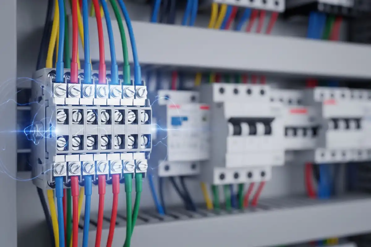
Close view of terminal block bodies, metal conductors, screws, and molded insulation
Appearance cannot establish a rating. Image: SENTOP article media. Material, geometry, spacing, conductor conditions, and approvals must be confirmed from exact product evidence.
A

Component identity

Use exact order numbers and revision-controlled data, not a family photograph or headline rating.

B

Accessory relationship

Verify bridges, plates, markers, test plugs, covers, and end stops for the exact terminal system.

C

Assembly context

Review adjacency, rail, enclosure, routing, temperature, and protective-device context together.

D

End-product evidence

A component mark or test result does not certify the completed rail, enclosure, machine, or panel.

Important distinction:

IEC short-time withstand current is not a dynamic short-circuit capacity or the final panel SCCR. A shield clamp is not a protective-earth terminal. A test/disconnect block is not automatically a load-break switch, isolator, or lockout disconnect. A fuse block may provide only the protection described for that exact product and circuit.

Seven-step engineering workflow

Move from problem to released configuration

The workflow is deliberately linear. Every step produces a reviewable output, so purchasing, engineering, production, and quality can work from the same revision.

01Define

State the measurable problem

Record circuit function, conductor material/construction/cross-section, voltage, current, fault environment, insulation needs, ambient conditions, available space, service access, annual volume, target market, and the specific cost or risk to remove.

Required output

Application requirement with quantified constraints and a named engineering owner.

02Search

Search catalog systems before tooling

Check alternate connection technologies, compact or multilevel blocks, functional terminals, native accessories, configured PCB families, and assembly services. Document why each promising direction passes or fails; avoid rejecting a family on appearance alone.

Required output

Shortlist, comparison matrix, and recorded gap that justifies the customization level.

03Configure

Create the controlled terminal schedule

Translate the schematic into exact terminal positions, functions, bridges, separators, end plates, covers, test points, markers, wire IDs, orientation, rail location, and enclosure relationship. Package the released configuration using the mixed terminal-block BOM guide.

Required output

Terminal schedule, jumper map, marker file, exact BOM, and preliminary rail layout.

04Review

Review the complete electrical assembly

Verify conductor acceptance and preparation, current and voltage data, temperature conditions, insulation coordination, fault-current basis, protective context, adjacent potentials, bridges, functional accessories, PE or shield role, and the finished installation. Use exact documentation when reading terminal-block specifications.

Required output

Signed technical checklist with evidence references, open issues, and deviations.

05Freeze

Freeze the quote and pilot package

Request drawings, dimensional data, 3D models where needed, exact part numbers, rail length and end locations, BOM, marking preview, approval evidence, inspection method, packaging, tooling or NRE, lead time, minimum order, and revision identification. Resolve deviations before a sample is built.

Required output

Supplier quotation linked to one frozen drawing and configuration revision.

06Pilot

Build, fit, and inspect a pilot

Under qualified and de-energized procedures, check component identity, dimensions, mounting, label legibility, wire approach, bend space, tool and test access, bridge map, end parts, enclosure fit, service replacement, and the defined electrical or mechanical acceptance tests. Compare the pilot against the released pack, not memory.

Required output

Approved sample, inspection record, photos, deviations, and closure evidence.

07Release

Release production and control change

Archive the approved drawing, BOM, terminal schedule, marker artwork, jumper map, certificates, test records, inspection criteria, golden sample, spares, and packaging reference. Require controlled substitution and product-change-notification review; revalidate every affected condition after a revision.

Required output

Production release with revision history, incoming checks, spares plan, and PCN path.

Eight validation gates

What must remain true after customization

Validate the configuration as a system. A terminal can accept the wire physically and still fail on conductor construction, temperature, insulation path, accessory compatibility, functional classification, or approval scope.

01

Conductor and clamp

Confirm copper or other permitted material, solid/stranded/fine-stranded construction, cross-section, preparation, ferrule conditions, strip length, quantity per clamping point, and insertion access.

02

Current, voltage, and heat

Use the applicable rating column and test condition for the exact model. Review continuous load, temperature rise, ambient temperature, enclosure, neighboring heat sources, and bridge limits.

03

Creepage and clearance

There is no universal spacing value. Verify impulse and insulation voltage, pollution degree, material group, altitude, adjacent potentials, terminal sequence, barriers, housing, and final installation. Use the current IEC 60947-7-1 requirements overview as a scope primer.

04

Fault and panel SCCR

Do not convert short-time withstand data into panel SCCR. Confirm available fault current, protective device, component evidence, feeder and branch context, and the applicable finished-panel method. Review the short-time withstand current boundary.

05

PE, neutral, and shield roles

Protective earth and EMC shield connections are different functions. Green/yellow identification is not a cosmetic option. Verify the terminal’s bonding path, marking, approvals, and final protective-bonding design through the standards and certificates path.

06

Fuse, disconnect, and test function

Verify the exact operating sequence and switching limits. A test/disconnect block is not automatically suitable for breaking load or serving as a LOTO isolator. CT secondary circuits require the documented product-specific shorting sequence before opening.

07

Complete accessory system

Rail profile alone does not prove compatibility. Bridges, PE contacts, end plates, partitions, covers, markers, test plugs, and end stops can be family-specific—even within one brand. Do not assume accessories are interchangeable.

08

Target-market evidence

Confirm the exact model, certificate scope, Conditions of Acceptability where applicable, assembled configuration, target country, equipment standard, and required records. A family logo or component mark does not approve every variant or the final panel.

Mixing brands is an engineering decision, not a shortcut. Third-party components may coexist on a professionally engineered rail, but cross-brand bridges, PE contacts, end plates, test accessories, or barriers need documented compatibility and a named assembly-level owner. Keep substitutions under formal review.

What the market already supports

Configuration can be a controlled service

Manufacturer services demonstrate that “custom” often means digitally configured, documented, and preassembled proven components. They illustrate the workflow; they do not select or approve a SENTOP configuration.

Rail assembly example

Weidmüller: configured and assembled terminal rails

Weidmüller describes ready-to-install, fully equipped and marked terminal rails, plus a configurator that supports terminal selection, accessories, BOMs, drawings, ECAD workflows, verification, quotation, and assembly requests. This supports a key sourcing lesson: the terminal strip, its accessories, and its documentation can be purchased as one released configuration.

PCB configuration example

WAGO: property-based PCB connection design

WAGO’s Smart Designer workflow lists pole number, pin spacing, conductor cross-section, color, actuation type, solder-pin arrangement, coding, and marking as configurable parameters, with configuration-specific 3D models and data sheets. The resulting configuration still requires board, mating, electrical, mechanical, and end-product verification.

Brand examples are factual capability references, not rankings, endorsements, or evidence that every option is available for every series, country, quantity, or approval.

Illustrative repeat-panel case

Customize the assembly and identification, not the current path

A builder produces repeated water-treatment control panels containing incoming power, PLC I/O, field wiring, fuses, PE positions, and customer-specific labels. The catalog terminals are technically adequate, but technicians build each rail from a spreadsheet. Wrong jumpers, inconsistent labels, omitted end plates, and spacing errors create inspection and rework.

Problem definition

Variation occurs in rail cutting, terminal order, jumper placement, marking, and accessory completion—not in the underlying connection technology.

Least-complex solution

Use the same proven catalog blocks in a preassembled, fully marked rail with a frozen schedule, jumper map, drawing, BOM, and complete accessories.

Pilot acceptance

Inspect exact identities, dimensions, label legibility, bridge map, end parts, cabinet fit, conductor approach, tool/test access, and service replacement.

Business evidence

Measure engineering hours, rail-assembly time, first-pass inspection, rework, commissioning issues, and field service—not only the terminal price.

Two technicians identifying terminal positions and wire labels in a control cabinet
Identification is an engineering interface. Image: SENTOP article media. The released terminal schedule, drawing references, wire IDs, and physical markers should agree.
Six-part RFQ

What to send for an actionable quote

A supplier cannot safely infer the circuit from a photo or a generic request for “custom terminals.” Send one package that connects application data to exact configuration and commercial controls.

01 · Electrical

Circuit and conductor

Function, system voltage and frequency, operating current, available fault current and protection, conductor material/construction/cross-section, preparation, quantity per point, and insulation requirements.

02 · Functional schedule

Every terminal position

Feed-through, PE, neutral, distribution, fuse, disconnect, test, shield, sensor, or other function; terminal IDs, potential groups, bridge map, wire IDs, spare positions, and test points.

03 · Mechanical

Rail, panel, PCB, and access

Rail type and length, maximum envelope, terminal orientation, cable-entry direction, bend space, enclosure relationship, tool/test access, mounting holes, PCB footprint, mating direction, and 2D/3D files.

04 · Identification

Markers, colors, and artwork

Marker text and file format, label hierarchy, language, logo or artwork, approved color scheme, PE/neutral rules, print durability, barcode or traceability fields, packaging labels, and golden sample.

05 · Compliance

Environment and evidence

Ambient range, enclosure/IP context, pollution, altitude, vibration, condensation, chemicals, corrosion, target market, equipment standard, certificate scope, test reports, Conditions of Acceptability, and required inspection records.

06 · Commercial controls

Volume, revision, and supply

Prototype and annual quantity, forecast, tooling/NRE, sample plan, target dates, Incoterms, packaging, spares, approved substitutions, PCN expectations, revision ownership, warranty, and repeat-order identification.

Send the drawing package before requesting a substitute.

Use SENTOP’s OEM/ODM service-support brief and supplier-qualification guide to connect the quotation, pilot, and production release.

Buyer and engineering FAQ

Customized terminal blocks: practical answers

These answers define the decision boundary. The exact product data and finished-equipment requirements still control.

What makes a terminal block “customized”?

Customization can mean approved colors, marking, coding, jumpers, accessories, terminal sequence, rail length, preassembly, PCB pole or pin configuration, packaging, or documentation. It does not always mean a new molded or current-carrying component. Name the level explicitly so the supplier knows whether the request is a configuration, an assembly service, or a new design.

Are customized terminal blocks always more expensive?

They can raise unit price, engineering cost, tooling, minimum order, or lead time. A configured rail may still lower total installed cost by reducing design work, rail assembly, marking, inspection, rework, commissioning errors, and service time. Compare complete lifecycle cost and expected volume, not the terminal price alone.

What parts of a terminal block system can be customized?

Common options include marker text, color within an approved range, coding, pole count, pitch, actuation, solder-pin arrangement, terminal sequence, rail length, bridges, separators, end plates, covers, test points, wire IDs, packaging, and documents. Availability and ratings depend on the exact family. New geometry, material, housing, or current paths need a separate engineering and validation scope.

Do custom markings affect electrical performance?

A compatible marker normally does not change the current path, but it must fit the intended marking system, remain legible in the environment, preserve required identification, and never claim a function the hardware does not provide. Green/yellow, PE, neutral, voltage, circuit, and warning identification must follow the applicable requirements and released drawing.

When is a new terminal-block design necessary?

Only when a documented search shows that standard terminals, native accessories, preassembled rails, and configurable product families cannot meet the verified electrical, mechanical, environmental, interface, compliance, production, or service requirement. The new design then needs defined inputs, drawings, risk review, verification tests, tooling control, approval strategy, samples, and change control.

How should an OEM control revisions to a custom terminal rail?

Freeze exact manufacturer part numbers, terminal schedule, BOM, rail drawing, dimensions, jumper map, marker file, accessory list, approval evidence, inspection criteria, packaging reference, and approved sample under one revision. Require written approval for substitutions and product-change notifications, and revalidate every rating or condition affected by a change.

Can a custom terminal rail mix brands?

It can, but only under documented engineering ownership. Shared DIN-rail mounting does not make jumpers, PE contacts, end plates, partitions, covers, markers, or test accessories compatible. Treat third-party components as part of the complete assembly review; do not create cross-brand current paths or safety functions without explicit evidence.

What should a customized terminal-block RFQ include?

Send the schematic, terminal schedule, wire list, circuit and fault data, environment, target market, rail or PCB dimensions, accessory and bridge map, marker artwork, quantities, forecast, sample and inspection plan, evidence requirements, packaging, spares, revision ownership, substitution rules, PCN expectations, and requested dates. Ask the supplier to identify every assumption and deviation.


Primary references

Standards and manufacturer evidence

Use these sources to understand scope and available engineering services. Purchase the applicable standards and retrieve current exact-model documents before design release.

  1. IEC 60947-7-1:2025 — terminal blocks for copper conductors and test-disconnect terminal blocks within the stated scope.
  2. IEC 60664-1:2020 + AMD1:2025 — insulation-coordination framework for low-voltage equipment.
  3. IEC 60947-7-2:2009 — requirements for protective-conductor terminal blocks.
  4. IEC 60445:2021 + AMD1:2026 — identification of equipment terminals and conductors.
  5. UL Solutions — Component Recognition and Classification — recognized components and Conditions of Acceptability in the end product.
  6. UL Solutions — Determining machinery SCCR — panel-level SCCR method and component context.
  7. WAGO — Interconnection Technology FAQ — manufacturer guidance on spacing, accessories, PE identification, and short-time current boundaries.
  8. Phoenix Contact — SCC 10-F product data — example of a shield clamp expressly not intended for protective-conductor connection.
  9. Weidmüller — Assembled terminal rails — configured, fully equipped, marked, ready-to-install rail services.
  10. Weidmüller Configurator — configuration, accessories, documentation, ECAD, BOM, and ordering workflow.
  11. WAGO — Easy PCB connection configuration — supported parameters, 3D models, data sheets, and sample path.
  12. WAGO — Marking solutions — manufacturer marking-system context.

Reviewed August 27, 2026. No universal compatibility, rating, certification, installed-cost saving, minimum order, lead time, or project approval is implied. Verify current exact-model documents, quotation terms, and finished-equipment requirements before purchase and release.

Turn the requirement into a controlled configuration

Send the schematic, terminal schedule, panel or PCB layout, standards, quantity, and target revision.

SENTOP can help organize model matching, configuration feasibility, samples, quotation, and supply requirements. Final engineering approval, panel assessment, installation, commissioning, and maintenance remain with the qualified project team.

滚动至顶部