

A Complete Analysis of the Process of Customizing Terminal Blocks
Reliable custom terminal blocks start with circuit, conductor, mechanical and market requirements—not a photo, color or ampere value. The process then controls the complete rail, accessories, marking, first article, inspection evidence and production release.
Customize the controlled assembly, not just the visible part
Customizing terminal blocks means translating the schematic, terminal plan and wire data into an exact, repeatable deliverable. That deliverable may be a standard terminal family arranged on DIN rail, a rail supplied with bridges and markers, a controlled assembly variant, or a newly engineered component. Those levels have different verification, tooling, lead-time and approval consequences.
A production-ready rail includes more than terminal bodies: DIN rail, end stops, end plates, partitions, approved cross-connections, markers, test interfaces, PE or functional terminals, wire-preparation data, inspection points, packaging and traceability all belong to the definition.
Responsibility boundary: this guide supports specification, sourcing and supply control. The responsible engineering and compliance parties still own the circuit design, protection strategy, adopted rules, hazardous-location decisions, certification route and finished-equipment approval.
Four levels with increasing engineering impact
Choose the lowest level that satisfies the application. Deviation from published combinations can add design review, samples, qualification work, certification review and longer change cycles.
Configured standard rail
Catalog terminal blocks arranged on a defined DIN rail with standard accessories and markers.
Verify product relationships, electrical grouping, rail length, documentation and exact order codes.Pre-assembled or kitted rail
A configured rail supplied with installed bridges, end stops, labels and agreed packaging.
Add assembly instructions, inspection points, marking proof and order-level traceability.Modified assembly
Special rail length, marking, wire preparation, component mix or enclosure interface.
Review mechanical fit, process changes and any effect on documented or certified use.Application-specific solution
A new body, clamp, current path, material, PCB interface or special-environment design.
Use formal design control, a qualification plan and the appropriate compliance pathway.Configuration is not a certification state. Standard approved components can simplify review, but a component logo, family resemblance or configuration screenshot does not certify the completed rail or panel. A changed construction may require review, testing or certification-file revision before any approval claim is made.
Move from requirements to a traceable production baseline
Each phase produces an auditable output for the next. Skipping an output simply moves uncertainty into assembly, commissioning or field service.
Capture the complete requirement
Record topology, conductors, ratings, protection, layout, environment, identification and supply conditions.
Review inputsBuild the rail architecture
Group circuit functions, define bridges, test or disconnect needs, PE and shield treatment, separation and spares.
See functionsSelect a matched system
Control terminal bodies, rail, end parts, bridges, markers, barriers, test accessories and wire-end treatment.
Match componentsCreate the engineering package
Release the terminal plan, BOM, drawing, marking proof, inspection plan and change record as one revision.
Open packagePrototype, verify and approve
Use the first article to verify identity, fit, wiring access, electrical intent, documentation and packing.
Review validationRelease controlled production
Use executable work instructions, inspection gates, traceability and authorized change control.
See controlsCapture seven inputs before selecting a part number
A terminal rail is the physical interface between field wiring, internal wiring, distribution, protection and service. Link the requirement record to the one-line, schematic, I/O list, terminal plan and panel layout. Mark unknowns as assumptions; a supplier cannot infer a neutral policy, bonding scheme or fuse strategy from a photo.
1. Electrical topology
Identify power, control, safety, analog, digital, communication, shield, neutral, PE and spare circuits. Show sources, common potentials and the field/panel boundary.
Inputs: one-line, schematic, I/O list and terminal plan.2. Conductor data
Record copper or other approved material, AWG/mm², solid/stranded/fine-stranded construction, insulation outside diameter, ferrule or lug policy and conductor count per clamp.
Inputs: wire list, cable schedule and approved preparation method.3. Ratings and protection
Define system voltage, continuous and transient current conditions, load duty, upstream protection, required fuse or disconnect function and the project fault/protection context.
Inputs: load schedule, protection basis and applicable design rules.4. Mechanical layout
Specify rail profile and material, usable length, enclosure depth, wire-entry direction, bend space, duct clearance, tool access, cover removal and service approach.
Inputs: panel GA, 3D model and enclosure drawing.5. Environment
State indoor or outdoor use, temperatures, vibration/shock, contamination, corrosion, enclosure conditions and whether hazardous-location, railway, marine or other sector requirements apply.
Inputs: environmental specification and installed location.6. Identification
Define terminal and wire numbering, colors, bilingual text, marker orientation, barcodes, customer part numbers, required product markings and as-built update rules.
Inputs: labeling standard, title block and controlled marker data.7. Supply model
Record sample date, prototype and production quantities, lot size, kitting, packaging, traceability, service spares, approved alternates and product-change notification expectations.
Inputs: forecast, purchasing terms and quality agreement.State the jurisdiction and target approval route now. Public standard pages help identify relevant scope; they do not replace the full standard, the exact component certificate, Conditions of Acceptability or the finished-equipment review.
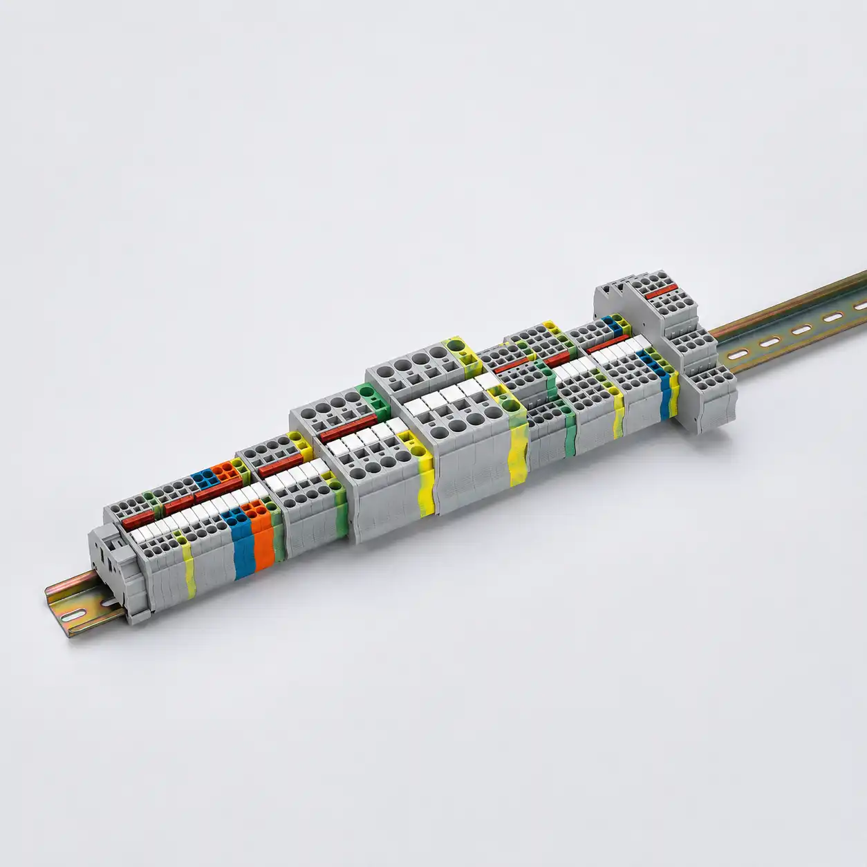
Group circuits by function, energy and service intent
Translate the schematic into understandable groups for high-energy power, control, sensitive analog, communications, PE, shield treatment and spares. Show every intended bridge and every defined test or disconnect point; technicians should not need to reverse-engineer unmarked cross-connections.
- Separate functions deliberately: use project-defined spacing, partitions, routing and access rules—not color alone.
- Control every common potential: use the exact bridge family, pole count, position and documented current conditions.
- Keep PE, functional earth and shield treatment distinct: the circuit purpose and approved bonding path decide the function.
- Define service behavior: disconnect, test and fuse terminals are not automatically load-break switches, safety isolators or proof of de-energization.
General conductor path
Choose connection technology, conductor range, levels, color, markers and test access from the exact product family.
Defined PE/PEN path
Verify the protective-conductor function, rail/support interface, mounting, conductor range and inspection access. Green-yellow color alone proves nothing.
Project-specific neutral handling
Define the topology, permitted disconnect function, grouping, marking and procedure under the adopted project rules.
Specified fuse-link interface
Match fuse format/class, voltage, breaking capacity, load and heat, indication, coordination, access and replacement procedure.
Documented circuit break point
Define the circuit, link state, cover, test interface and approved service method. An ordinary disconnect terminal is not a CT shorting/test block. Never open-circuit the secondary of a conventional current-output CT while primary current may flow; use only the documented shorting/test arrangement and equipment procedure. Do not infer load-break or safety-isolation duty.
Controlled connection density
Map each level, commoning or separation, wire-entry direction, heat context, markers and service accessibility.
Integrated circuit function
Record internal diagram, polarity, electrical limits, dissipation, diagnostics, failure mode and replacement reference.
Defined EMC termination
Specify clamp style, cable diameter, rail or bonding interface and system grounding strategy. Shield, PE and signal reference are not synonyms.
Current is only one condition. Also verify the accepted conductor and preparation, terminal voltage conditions, total distribution path, jumper limits, thermal context, separation, access and the exact fault/protection arrangement. Creepage and clearance cannot be inferred from pitch or CAD appearance alone.
Small accessories decide whether the complete rail works
End plates, end clamps, partitions, bridges, markers, test plugs and rail are functional assembly parts—not purchasing afterthoughts. Configuration tools can preserve manufacturer-specific relationships, but the released BOM and responsible review remain the production authority.
Use digital tools as controlled evidence, not automatic approval. A configurator can reduce transmission and accessory-selection errors when it uses current product data. It cannot prove real wire-bend access, marker readability, application protection, all environmental conditions or finished-equipment compliance.

| Component | Verify | Frequent omission to prevent |
|---|---|---|
| Terminal block | Connection technology, accepted conductor construction and count, ratings, function, color, levels and exact approval evidence. | Assuming one clamp accepts both the field wire and a fine internal wire without checking each condition. |
| DIN rail and end stops | Rail profile/material, cut length, support and bonding concept, retained load, end-stop position and corrosion environment. | Treating the rail and end stops as packaging instead of assembly components. |
| Cross-connection | Exact family, pitch, pole count, installed position, current path, insulation/cover and permitted modification. | Using a visually similar bridge or leaving the commoned group ambiguous. |
| Markers | Text, circuit reference, sequence, orientation, print method, durability, language and spare positions. | Approving the electrical arrangement before a final marker proof exists. |
| Covers and partitions | Required separation, touch-protection objective, voltage-group boundary, operation and inspection visibility. | Adding barriers after the available rail space has already been consumed. |
| Test accessories | Exact test interface, approved procedure, access and lead/plug compatibility for the circuit. | Publishing a test plan without a usable physical connection point. |
| Wire-end treatment | Strip length, ferrule or lug rule, terminal count per clamp, specified torque or actuation and inspection method. | Mixing bare and ferruled fine-stranded wire without exact product and process data. |
Make the order reproducible without an email thread
Assign each rail a unique assembly ID and revision. Link every terminal position to its circuit reference, product line, bridge group and marker data. The BOM, drawing and print file must describe the same physical configuration.
Terminal plan
Position number, field/panel side, circuit reference, potential, function, bridge group, PE/shield treatment and spare status.
Controlled BOM
Exact manufacturer, order code, description, quantity, approved revision and governed alternate for terminals, rail and every accessory.
Assembly drawing
Rail profile and cut length, orientation, sequence, end parts, partitions, bridge locations, dimensions and packing orientation.
Marking proof
Terminal and wire strings, font and orientation, bilingual or barcode data, blank/spare positions and authorization to use a customer logo.
Inspection plan
Identity and sequence checks, critical dimensions, approved electrical checks, marker proof, photographs, sampling and acceptance evidence.
Change-control record
Released baseline, authorized deviations, substituted item review, expiry or quantity limit, approvals and as-built revision ownership.
Supporting release data: include the jumper map, rail cut list, wire/strip data, packing instruction and open-deviation list. A temporary deviation must have an approver, affected quantity or serial range and expiry; it must not silently become the next production baseline.

Use the first article to expose assembly and service problems
Prototype or first-article review is especially useful for a new or dense rail, a modified configuration, safety-relevant service, demanding environment, new supplier or transferred production route. Use representative wires and the intended mounting boundary—not an empty rail viewed on a desk.
Keep three gates separate. Supplier first-article approval, a customer PPAP where contractually required, and a UL Initial Production Inspection are different activities. Passing one does not grant IEC/UL certification or authorize an approval mark.
Design review
Trace schematic to terminal plan; review groups, ratings, separation, bridges, PE/neutral/shield strategy and closed assumptions. Evidence: signed checklist and redline closure.
First article
Reconcile exact order codes, sequence, markers, bridges, rail, end stops and accessories. Record measured rail length, photographs, sample identity and disposition.
Wiring simulation
Check representative conductor entry, bend and preparation, marker visibility, test and tool access, cover operation and replacement space in the panel boundary.
Electrical checks
Use the responsible engineer's approved plan for continuity, intended cross-connections, polarity, unintended shorts and defined fuse/disconnect behavior. Do not invent generic test values.
Compliance review
Verify exact model markings, certificates or recognition, conductor suitability, Conditions of Acceptability and project-specific environmental or finished-equipment requirements.
Packaging review
Confirm rail retention, protection of markers and operating parts, kit completeness, traceability, shipping orientation and a receiving checklist linked to the revision.
No single “custom terminal block test” proves every variant. Build the test matrix from the changed features, intended ratings, conductor conditions, environment and certification route. Depending on scope, it may include mechanical retention and connecting capacity; electrical spacing, withstand, voltage drop, temperature or short-time behavior; and applicable material, flammability, corrosion or environmental evidence.
Turn the approved sample into a repeatable production process
Use a traveler or digital work instruction that shows rail orientation, terminal sequence, bridge locations, marker strings and inspection gates. Control look-alike parts and define stop-ship, rework and deviation rules before an exception occurs.
Part identity
Scan or verify exact manufacturer order code, controlled revision and kitted bin to prevent look-alike terminal or bridge substitution.
Position and orientation
Use position-referenced visual instructions to prevent reversed rails, skipped positions and incorrect terminal sequence.
Jumper map
Verify every bridge against the released map and intended common potential; ambiguous cross-connections are stop-ship conditions.
Marking
Lock the print-file revision, inspect the first and final marker sets and compare them with the released terminal plan.
Connection preparation
Control strip length, ferrule or lug rule, specified screw torque or spring/push-in actuation and the corresponding inspection method.
Final electrical test
Run the assembly-specific approved checks and retain the result against the assembly identity; do not use a generic sequence across unlike functions.
Traceability
Record lot/date, operator or station, configuration revision, test disposition, deviations and packaging identity for repeat orders and corrective action.
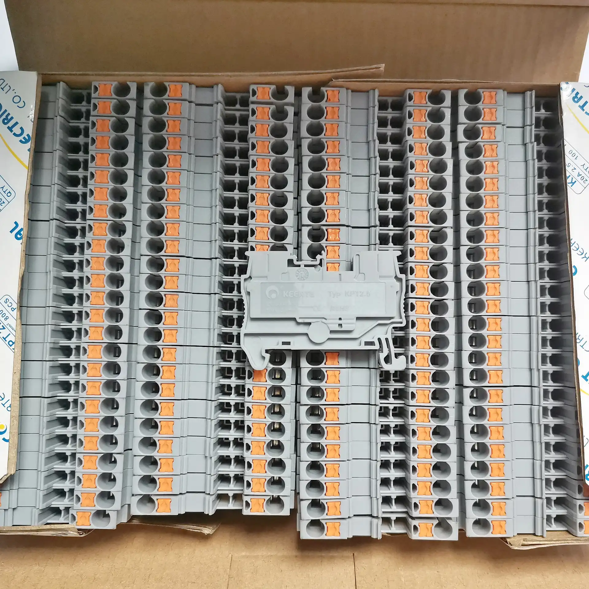
Freeze the approved baseline. Resin or pigment, contact and clamp geometry, plating, conductor range or preparation, spacing, mounting foot, fuse or indicator circuit, bridge system, tooling, critical supplier and production location can all require impact review. For certified products, submit relevant construction changes for acceptance before they appear on products bearing the mark.
Replace four shortcuts with controlled deliverables
Assume a machine panel needs 24 VDC distribution, PLC digital I/O, analog sensors, PE and service-test points. First separate those functions on the terminal plan. Then release the exact bridge groups, marker data, required partitions, test locations, PE positions and numbered spares. Verify the prototype with representative wire bundles.
24 VDC distribution
- SHORTCUT
- Cut bridge pieces added informally during panel wiring.
- CONTROL
- Released bridge map and exact approved bridge order codes in the rail BOM.
Analog and signal identification
- SHORTCUT
- Same-color positions with handwritten labels.
- CONTROL
- Defined marker format, circuit references and an approved print-file proof.
Protective-conductor path
- SHORTCUT
- PE terminals placed wherever rail space remains.
- CONTROL
- Planned PE group with documented support relationship, exact products and inspection access.
Future expansion
- SHORTCUT
- Unidentified empty rail length reserved “for later.”
- CONTROL
- Numbered spares, end-stop and partition strategy, protected accessories and as-built records.
Find the root cause before production release
These failures usually originate in missing inputs or disconnected records, not in the final assembly station alone.
Correct circuit, impossible wiring
Cause: no bend, entry or tool-access review. Prevent: use representative conductors and the actual panel boundary before release.
Missing bridges or end parts
Cause: the BOM contains terminal bodies only. Prevent: run an accessory relationship review and kit-completeness check.
Marker mismatch at commissioning
Cause: labels were retyped outside released data. Prevent: generate markers from the terminal plan and approve a locked proof.
The specified wire does not fit
Cause: only nominal AWG/mm² was recorded. Prevent: include construction, insulation OD, preparation and conductor count.
Uncontrolled field changes
Cause: no assembly ID or revision ownership. Prevent: control deviations and require an authorized as-built update.
Approval issue found late
Cause: market, environment or special-use scope appeared after the prototype. Prevent: engage responsible compliance reviewers in Phase 1.
Use the exact scope—never a blanket approval claim
Standards, certificates and recognition records apply to defined products and conditions. Confirm the edition adopted by the project and obtain the full documents required for the actual design review.
General and test-disconnect scope
Covers defined support-mounted terminal and Annex-D test-disconnect blocks with screw or screwless clamping for round copper conductors. It is not blanket approval for PE, fuse, electronic, aluminium or PCB constructions.
Protective-conductor terminals
Addresses PE/PEN terminal blocks for copper conductors and the conductor-to-fixing-support path. Color, a metal foot or DIN-rail mounting alone does not create a compliant protective-conductor function.
Fuse terminal blocks
Applies to defined fuse terminal blocks for copper conductors accepting IEC 60127-2 cartridge fuse-links, in circuits up to 1,000 V AC or 1,500 V DC and with a maximum short-circuit breaking capacity of 1,500 A. The stated scope assumes installation in equipment enclosures that make the terminals accessible only with a tool. It is not a universal panel SCCR, available-fault-current or branch-circuit-protection claim.
Component and end-product context
A UL Recognized Component is intended for integration into a larger certified product under stated Conditions of Acceptability. Verify the exact file, category, model, ratings and use conditions; Recognition is not Listing of a complete rail or panel.
Adjacent constructions require their own route. PCB terminal blocks and aluminium or copper-to-aluminium terminals have different IEC publications and evidence. Modified materials, current paths, mounting or functional circuits may require qualification and certification-file review even when a standard product in the same family is already covered.
Quote a stable configuration, not a provisional parts basket
Tell the supplier what is fixed by the customer, which engineering or configuration work is in supply scope and which substitutions require written approval. Attach controlled source files instead of relying on screenshots.
Minimum useful attachment set: schematic or terminal plan, wire and cable data, panel layout, target markets and environment, terminal sequence, label file, sample/inspection expectation, quantity forecast and approved-alternate policy.
Panel/equipment type, end market, country or region, applicable rules, environment and hazardous-location status. This sets the product and compliance review route.
Schematic, terminal plan, system conditions, source and protection data, functional groups, bridges, separation and service/test intent.
AWG/mm², conductor material and construction, insulation OD, ferrule/lug policy, count per clamp, labels and field/internal split.
Rail profile and cut length, ordered sequence, end parts, partitions, exact bridges, covers, test points, PE/neutral/shield groups and spares.
Terminal IDs, released print file, color policy, languages, barcode, assembly ID and customer part number. Include authorization for customer marks.
First article, photographs, dimensions, wiring mock-up, approved electrical checks, packing review, certificate evidence, traceability and acceptance records.
Prototype and production quantities, due dates, packaging, approved alternates, change notification, service spares and repeat-order data retention.
Custom terminal blocks, answered precisely
Clarify the supply boundary before drawings, certificates, tooling and delivery commitments are compared.
What is the difference between a custom terminal block and a custom terminal rail?
A custom terminal block can mean a modified component or new construction. A custom terminal rail is usually a configured assembly of documented terminal blocks and compatible accessories on DIN rail. Define the level first because engineering, qualification, certification review, cost and lead time differ.
What information is needed to customize terminal blocks?
Provide the schematic or terminal plan, conductor construction and insulation data, electrical and protection conditions, environment, rail and enclosure dimensions, marking rules, target markets and approvals, quantity, packaging, quality evidence and change-control requirements. A photograph alone is not enough.
Can terminal blocks be customized with logos and labels?
Marking and packaging can often be customized when the supplier's system supports them. Define the content, location, material, print method, durability, proof and trademark authorization. A custom label must not obscure required product markings, ventilation, test access or operating points.
How do I choose screw, push-in, or spring-clamp connection technology?
Compare the intended conductor material and construction, preparation, assembly process, tools, inspection method, maintenance practice, space, access and exact product evidence. Choose a terminal family whose approved instructions the production and service teams can execute consistently; do not substitute technologies by appearance.
Are custom terminal rails prewired?
The delivery can be loose components, a kitted rail, an assembled rail with bridges and markers, or a wired assembly when that work is explicitly in scope. Define every included operation, conductor, termination, label and approved test. Wire preparation by itself does not mean the rail is prewired.
Do terminal blocks need UL or IEC approval?
The required evidence depends on the target market, product category and finished equipment. Verify the exact terminal model, category or certificate, ratings and use conditions against the project route. A UL Recognized terminal block is a component for a larger end product; it is not a UL Listed rail or panel.
How can I prevent marking mistakes?
Generate the marker schedule from released terminal-plan data, approve a proof, lock the print-file revision, verify the first and final marker sets and retain the configuration revision with the order. Avoid retyping labels in an unlinked tool or changing them on the assembly bench.
When is a prototype necessary?
Use a prototype or first article when the rail is new, dense, modified, safety-relevant, transferred to a new supplier or process, or exposed to demanding conditions. Verify assembly, representative wiring access, markers, intended electrical paths, documentation and packaging. A prototype does not replace required type testing or certification.
Official sources for scope, evidence and change control
These public pages support the boundaries stated above. They do not replace purchased standards, exact certificates, model instructions, a project's adopted edition or the responsible approval process.
General and test-disconnect terminals
Protective-conductor terminals
Fuse terminal blocks
PCB and aluminium-adjacent scope
UL terminal-block standard
Component Recognition boundary
Digital rail configuration workflow
Testing, CT safety and certified-product changes
Phoenix Contact test principles · Schneider Electric CT warning · UL revision guidance
Send the terminal plan, wire data, market scope and quantity. Review the complete rail.
SENTOP can help organize terminal-block options, compatible accessories, marking, sample and supply requirements for review. Final circuit design, certification decisions and finished-equipment approval remain with the responsible project parties.