
Terminal Block Maintenance Checklist: 15 Safe Inspection Steps
Use this checklist to identify a terminal strip, make the work condition safe, inspect the complete connection system, control any testing or corrective work, and leave a traceable record. Exact manufacturer instructions and the equipment maintenance program—not a generic calendar—decide what is serviced and when.
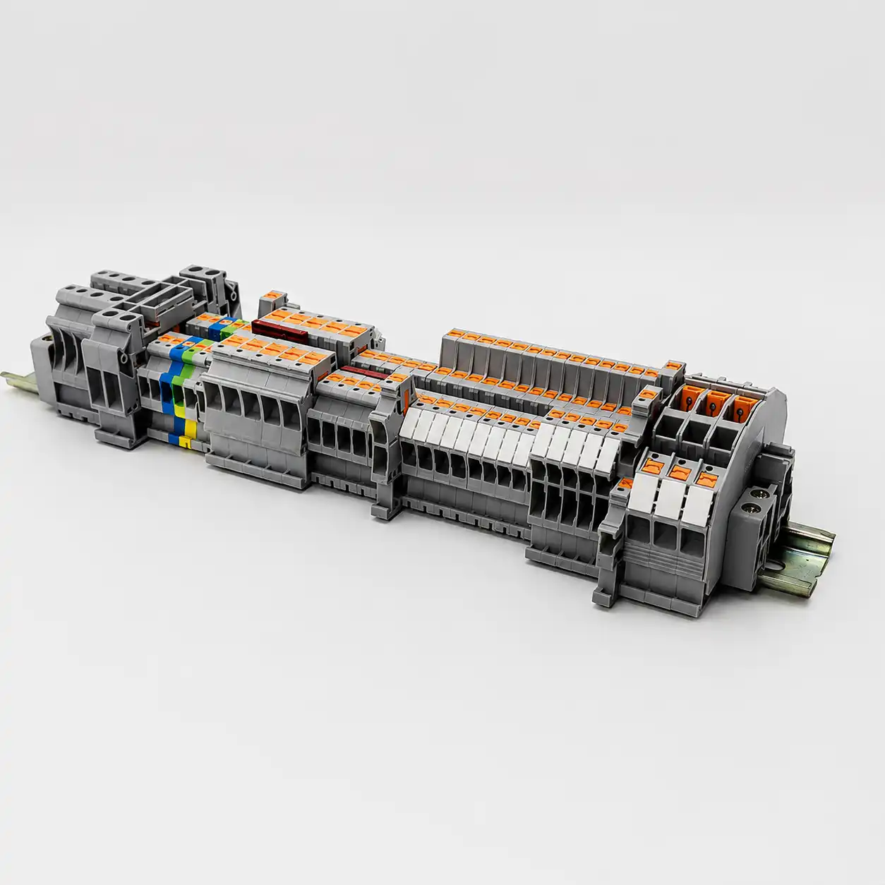
What should a terminal block maintenance checklist cover?
A useful terminal block maintenance checklist covers the safe work condition, asset identity, visible and mechanical condition, connection-specific instructions, controlled diagnostics, corrective action, restoration and records. It should help a qualified person decide what evidence is normal, what needs engineering review and what requires the equipment to remain out of service.
There is no safe generic inspection interval, re-torque schedule, pull force, insulation-resistance limit or thermal alarm value for every terminal block. Insert the exact model data, connected-equipment requirements, site risk assessment and electrical maintenance program before releasing the work order.
The same terminal strip can contain feed-through, PE, fuse, disconnect, test and multilevel functions. It can also connect sensitive electronics that could be damaged by an insulation-resistance tester. Treat the panel drawing, terminal schedule, equipment manual and current product instructions as part of the checklist—not optional background reading.
This guide does not authorize energized work, prescribe PPE, establish an arc-flash boundary or replace employer procedures. Maintenance and diagnostics must be planned and performed by people qualified for the specific equipment, voltage, hazards and test method.
Build the maintenance work package
A strong inspection starts with the current asset information. Without it, a technician cannot know whether the observed terminal, conductor, bridge or test result is correct.
Identify what is actually installed
- Panel, machine, circuit and terminal-strip identifiers
- Approved schematic, terminal plan, wire list and revision
- Exact terminal and accessory catalog numbers
- Conductor material, class, size and insulation data
- Normal load, duty, criticality and known operating history
- Previous findings, repairs, thermal images and open defects
Define the permitted work before the outage
- Employer energy-control and electrical-safety procedures
- Hazard and risk assessment for the planned tasks
- Manufacturer installation and maintenance instructions
- Specified cleaning products, tools and replacement parts
- Test method, instrument, isolation points and acceptance criteria
- Escalation owner, restoration checks and approval signatures
A family brochure or a torque copied from a similar-looking block is not enough. Product revisions can change conductor ranges, strip length, tool profiles, ferrule permissions, torque and accessories while the housing remains visually similar.
Establish the safe work condition before inspection
Under OSHA 1910.333 for covered U.S. workplaces, exposed live parts should be de-energized before work unless the employer can demonstrate one of the rule’s limited exceptions. Equipment that is switched off but not properly locked or tagged must still be treated as energized.
Follow the employer’s sequence.
Determine all sources first, including control supplies, UPS systems, generators, stored energy, induced voltage and backfeed. Disconnect them with appropriate isolating means, apply the required locks and tags, control stored energy and prevent restart.
Use suitable test equipment and the site procedure to verify exposed circuit elements and equipment parts are de-energized. A stopped machine, open contactor, dark HMI or non-contact detector alone is not proof.
The 15-step terminal block maintenance checklist
Work from identity and safety to observation, intervention and closeout. Mark “not applicable” with a reason; never convert an unperformed test into a pass.
Match the work order to the asset
Confirm the panel ID, terminal strip, circuit, drawing revision and exact physical location. Compare the installed terminal and accessory part numbers with the BOM and prior record before touching a conductor.
- Resolve duplicate, missing or unreadable asset labels.
- Note undocumented substitutions and field changes.
- Define which terminals are included and excluded.
Confirm qualifications, procedure and acceptance criteria
Assign people qualified for the equipment and each planned test. Review manufacturer instructions, the electrical maintenance program and the site hazard assessment. List the instruments, tools, replacement parts and independent checks required.
- Separate de-energized work from energized diagnostics.
- Define escalation and return-to-service authority.
- Record any instruction that prohibits re-tightening or disassembly.
Identify and control every energy source
Follow the employer’s electrical lockout/tagout procedure. Disconnect normal and alternate feeds, release or restrain stored energy, prevent automatic restart and address sources such as control power, UPS equipment, generators and capacitors.
- Do not use a push button or interlock as the sole isolation.
- Apply required locks, tags and group controls.
- Protect the boundary from unauthorized operation.
Verify the electrical work condition
A qualified person tests exposed circuit elements and equipment parts with suitable equipment according to the site procedure. Account for induced voltage, unrelated backfeed and instrument condition. Maintain protection from adjacent energized parts.
- Use the required instrument rating and proving method.
- Do not rely only on an indicator lamp or non-contact detector.
- Record the verification when the work package requires it.
Capture condition before cleaning or adjustment
Photograph the overall strip and each anomaly with terminal markers visible. Record enclosure condition, odor only if noticed without deliberate exposure, contamination, ambient conditions and the equipment state. Preserve evidence before it can be wiped away or disturbed.
- Use consistent views for later comparison.
- Do not touch carbonized or heat-damaged material to “check” it.
- Link every image to the asset and work order.
Inspect insulation and terminal housings
Look for discoloration, melting, deformation, cracks, embrittlement, carbonized tracks, pitting, soot and evidence of overheating. Compare adjacent positions, but do not infer the root cause from color alone.
- Flag any reduced separation or exposed conductive part.
- Check barriers, end plates and covers for damage.
- Keep severely damaged equipment out of service for disposition.
Inspect conductor entry and preparation
Check that conductors match the documented material, class and cross-section. Look for escaped strands, nicked insulation, excessive exposed copper, insulation inside the clamping zone, damaged ferrules, sharp bends, strain or signs that a conductor has backed out.
- Do not pull every wire with an invented force.
- Use a retention test only when an approved method defines it.
- Confirm that multi-conductor connections are expressly permitted.
Inspect rail mounting and accessories
Treat the terminal row as an assembly. Check the specified DIN rail or support, end brackets, end plates, partitions, bridges, test accessories, fuse or disconnect elements, PE arrangement and markers for correct position and secure seating.
- Look for rail corrosion, distortion or movement.
- Confirm bridges match the intended potentials.
- Check that covers and partitions preserve required separation.
Inspect contamination and enclosure controls
Record dust, moisture, condensation, oil, conductive debris, salt or chemical exposure, pest activity, blocked ventilation and failed enclosure seals. Evaluate the complete enclosure’s rating and condition rather than assigning an IP claim to an open terminal alone.
- Find the contamination path before cleaning.
- Review temperature, vibration and load changes.
- Escalate evidence of water or conductive deposits.
Review the connection instruction before using a torque tool
Identify the exact clamping technology and current manufacturer instruction. Some products are designated maintenance-free; others have a defined inspection or tightening procedure. Do not use a universal re-torque calendar or infer torque from wire gauge.
- Do not move a sound joint merely to obtain a “reading.”
- Where tightening is authorized, use the exact value and method.
- Use a suitable tool controlled by the site calibration program.
Check the mechanism by terminal type
For screw clamps, inspect the permitted conductor, screw and housing condition. For spring-cage or push-in designs, inspect the actuator, insertion point and spring mechanism without inventing a torque step. Follow separate instructions for bolt, lug, IDC, fuse, disconnect and test terminals.
- Never tighten a spring-pressure conductor clamp.
- Do not operate damaged actuators to “see if they work.”
- Replace parts only with an approved model and accessory set.
Clean only with an approved method
If cleaning is permitted, keep the equipment de-energized and use products and tools compatible with the terminal housing, markings, metal finishes and connected equipment. Prevent residue or debris from entering adjacent devices and allow the required drying time.
- Do not prescribe universal IPA, brushes or compressed air.
- Do not abrade plating or remove evidence before review.
- Do not apply oxide inhibitor unless the exact connection requires it.
Perform only specified de-energized electrical tests
Continuity, low-resistance or insulation-resistance testing must follow the connected equipment and project procedure. Isolate voltage-sensitive electronics and any parallel paths as required. Select test voltage, method and acceptance criteria for the circuit—not for a generic terminal block.
- A continuity beep does not qualify a low-resistance joint.
- Formal low-resistance measurements may require a four-wire method.
- Discharge and restore isolated equipment exactly as instructed.
Control and interpret any energized thermal survey
Thermography is useful only under known operating conditions and an approved energized diagnostic procedure. Compare like components under comparable loads, account for ambient conditions, emissivity, reflections, phase imbalance and harmonics, and preserve the thermal and visible images together.
- Record load, ambient temperature and inspection route.
- Use site or engineering criteria—never a universal delta-T rule.
- Investigate an anomaly; do not treat one pixel as a diagnosis.
Correct, verify, document and restore
Classify each finding, assign an owner and complete the approved action. Reinspect repaired positions, update drawings and BOMs, remove tools and temporary jumpers, reinstall covers, confirm personnel are clear and follow the controlled release from lockout/tagout.
- Record replaced model numbers and conductor preparation.
- Attach test results and before/after photos.
- Set the next interval from condition, criticality and governing instructions.
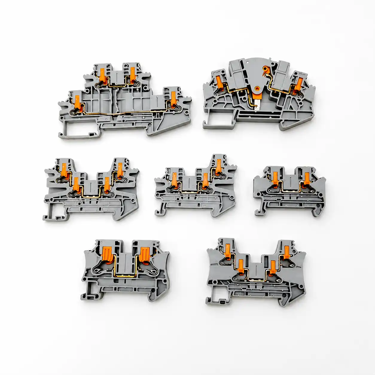
Screw, spring-cage and push-in terminals are not serviced the same way
Connection technology changes what can be inspected or adjusted. The exact product instructions remain the controlling source.
Do not assume periodic re-torque
Use the manufacturer’s service instruction for the exact screw-clamp design. Some screw terminals are expressly described as maintenance-free, while other equipment may define an inspection or tightening task.
- Torque is model- and connection-specific.
- Do not infer a maintenance value from AWG.
- Do not disturb a joint without an authorized method.
Inspect; do not add screw-clamp work
Spring pressure maintains the conductor contact without a conductor-clamp torque value. Inspect insertion, housing, actuator, conductor and thermal condition as applicable.
- Do not insert a torque tool into the actuator.
- Use only the intended operating point.
- Replace a damaged mechanism as instructed.
Verify the permitted conductor preparation
Direct insertion depends on conductor type, size and product design. Inspection should confirm full seating, permitted ferrule or bare-wire preparation and correct actuator position.
- No conductor-clamp torque applies.
- Do not pull-test with a generic force.
- Use the model’s removal and reinsertion method.
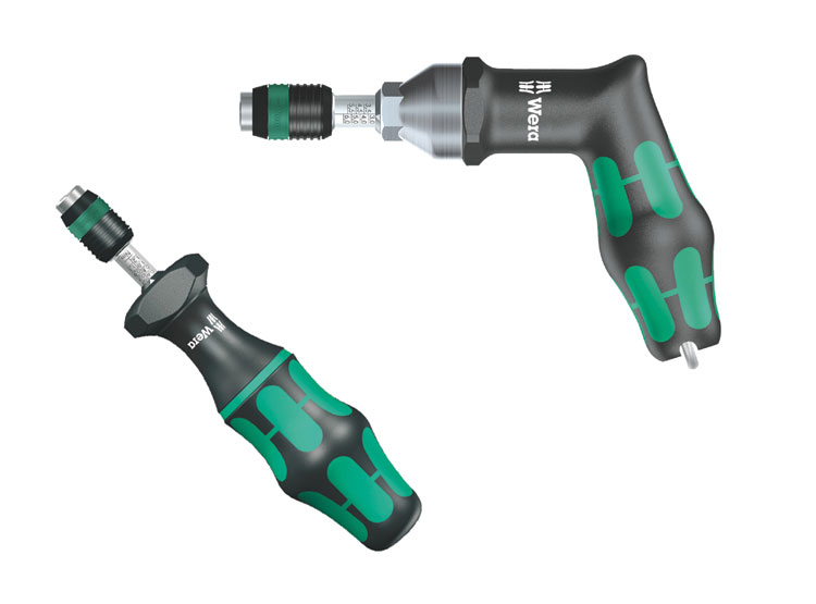
Use diagnostics to investigate evidence—not to manufacture certainty
A thermal image, resistance value or continuity result only becomes meaningful when the test method, circuit state, loading and acceptance criteria are defined.
Compare equivalent points
- Qualified-person energized procedure
- Comparable load and operating state
- Ambient, emissivity and reflection controls
- Thermal plus visible image
- Trend against a valid baseline
Use the specified method
- De-energized and isolated circuit
- Parallel paths understood or removed
- Four-wire method where required
- Lead compensation and instrument checks
- Project-specific acceptance criteria
Protect connected electronics
- Defined test boundary and voltage
- Sensitive devices isolated as instructed
- Stored energy safely discharged
- Temperature and time recorded if relevant
- Equipment or standard criterion applied

When to clean, investigate, reterminate or replace
Preserve evidence, remove the equipment from service when the condition is unsafe, and use an engineering or manufacturer-approved disposition. Appearance alone cannot prove the root cause.
Document and investigate
Unexpected temperature, localized discoloration, intermittent operation, abnormal voltage drop, repeated loosening or new contamination needs a cause-based investigation.
Clean only when permitted
Remove loose contamination only under an approved de-energized method using compatible products. Correct leaking seals, cooling or contamination sources.
Reterminate under instruction
If the conductor or preparation is defective, use the exact strip length, ferrule permission, conductor range and torque or actuation method for the selected terminal.
Replace or escalate damage
Cracking, melting, carbonized tracking, arcing, severe corrosion, damaged springs or stripped hardware generally cannot be made reliable by wiping or tightening.
Investigate the upstream cause
A replacement will fail again if overcurrent, conductor mismatch, vibration, heat, moisture, chemical exposure or poor enclosure control remains.
Verify after correction
Inspect the new connection, complete the specified electrical checks, update the BOM and drawings, then establish a follow-up condition check if the maintenance program calls for one.


How often should terminal blocks be inspected?
Do not convert “daily, monthly, quarterly and annual” into a universal schedule. Establish the interval inside the equipment maintenance program using the exact equipment instructions, assessed condition, duty, environment, criticality and history.
| Decision input | Evidence to review | How it affects the interval |
|---|---|---|
| Manufacturer and OEM instructions | Model-specific inspection, tightening, replacement and environmental guidance | Sets mandatory tasks, prohibitions and maximum intervals where stated. |
| Equipment condition assessment | Documented condition, maintenance history, open deficiencies and program classification | Moves impaired or unknown-condition equipment to closer review and corrective action. |
| Duty and criticality | Load profile, cycling, continuity requirements and consequence of failure | Prioritizes connections whose failure has higher safety, production or service impact. |
| Environment | Heat, vibration, moisture, dust, chemicals, salt, altitude and enclosure condition | Increases monitoring or drives enclosure improvement when stress or ingress is present. |
| Change or abnormal event | Load increase, modification, trip, flooding, overheating, repair or repeated anomaly | Triggers qualified evaluation outside the routine interval. |
| Trend data | Comparable thermal images, findings, repairs and valid test results over time | Supports a documented interval adjustment instead of an arbitrary calendar. |
NFPA publishes NFPA 70B as a Standard for Electrical Equipment Maintenance. It is a program-level source for condition assessment and maintenance planning, not proof that every terminal screw must be tightened quarterly or annually. Use the edition that applies to the organization, contract and authority context.
Terminal block maintenance record template
Copy these fields into the site form or CMMS. Preserve raw observations separately from the disposition so a later reviewer can see what was actually found.
Make every record traceable.
A useful record identifies the exact connection, work condition, evidence, decision and responsible people. “Panel checked—OK” cannot support trending, replacement selection or root-cause review.
Add the reason, owner and due date for every item that is not an unconditional pass. Never use “N/A” to hide a skipped task.
Prepare a replacement terminal block BOM review
A photo and wire size alone do not establish an interchangeable replacement. Capture the electrical, mechanical, environmental and approval requirements before ordering.
Replace the complete function—not only the housing shape.
SENTOP can review a terminal schedule, model list, drawings or clear panel photos together with the required connection technology, accessories and supply details. Final ratings, approvals, availability, MOQ, samples and lead time must be confirmed for the selected model and order.
Need a model-by-model terminal block replacement review?
Share the terminal model, conductor size, circuit rating, DIN rail type, panel photos, required approvals and replacement quantity.
Related SENTOP resources
Use the maintenance checklist as the control layer, then open the focused guide for installation, temperature, specifications or fault diagnosis.
Terminal block maintenance checklist FAQ
Short answers to the decisions most likely to change the maintenance work order.
How often should terminal blocks be inspected?
Set the interval through the equipment maintenance program using the exact manufacturer and OEM instructions, equipment condition, duty, environment, criticality, history and applicable requirements. There is no universal quarterly or annual interval for every terminal block.
Should screw terminal blocks be re-torqued during maintenance?
Only when the exact product or equipment instruction and authorized maintenance procedure call for it. Do not apply a universal re-torque schedule or use a torque tool merely to obtain a residual reading; some screw-clamp products are designated maintenance-free.
Do spring-cage or push-in terminal blocks need re-tightening?
The conductor is held by spring pressure rather than an installation screw torque, so a routine re-tightening step does not apply. Inspect the housing, conductor seating, actuator, accessories and thermal or electrical condition as required by the exact instructions.
Can thermal imaging be performed on energized terminal blocks?
Thermography often needs representative load, but it is an energized diagnostic task. It should be performed only by qualified personnel under the employer’s approved electrical-safety procedure, with controlled access and interpretation that accounts for load, ambient conditions, emissivity and comparable points.
When should a damaged terminal block be replaced instead of cleaned?
Cracking, melting, carbonized tracking, arcing damage, severe corrosion, damaged springs or stripped hardware generally requires the equipment to remain out of service until the manufacturer or responsible engineering authority provides a replacement or disposition. Cleaning cannot restore damaged insulation or contact geometry.
What information should a terminal block maintenance record include?
Record the asset and terminal position, exact product and conductor, work condition, observations, photos, test method and conditions, acceptance criteria, corrective action, replacement parts, post-work verification, responsible people and the basis for the next interval.
Can an insulation-resistance tester be connected through terminal blocks?
Only under a defined circuit-level test procedure. Isolate voltage-sensitive electronics and parallel paths as required, select the correct test voltage and acceptance criteria, and discharge and restore the circuit safely. Do not apply a generic megger test to an assembled control circuit.
What specifications are needed to source a replacement terminal block?
Provide the existing full model, terminal function, voltage and current, conductor material, class and size, connection technology, mounting or rail, positions and levels, accessories, environment, required approvals, quantity and clear photos or drawings.
References and further reading
Official work-practice, maintenance-program, torque, testing and manufacturer sources used to verify this checklist.
- OSHA. 1910.333—Selection and use of work practices.
- OSHA. 1910.334—Use of electrical test instruments and equipment.
- OSHA. Relationship of 1910.147 and 1910.333 energy-control requirements.
- NFPA. NFPA 70B—Standard for Electrical Equipment Maintenance, 2026 edition page.
- NFPA. Official NFPA 70B-2026 development text for maintenance programs, connection quality, cleaning, thermography and frequency.
- NEMA. Bulletin No. 120—Using Torque Tools for Terminating Building Wire.
- NIST. Recommended calibration interval—why one universal interval is not prescribed.
- Phoenix Contact. Terminal-block connection technologies and manufacturer maintenance-free design statements.
- WAGO. Electrical interconnections and spring-pressure maintenance guidance.
- Fluke. Electrical thermal-inspection method and comparison guidance.
- Fluke. Insulation-resistance testing and isolation of electronic controls.
- UL Standards & Engagement. UL 1059, Terminal Blocks, Sixth Edition.
- IEC. IEC 60947-7-1:2025, terminal blocks for copper conductors.
