

How to Calculate DIN Rail Space for Terminal Blocks
Build the calculation from the exact installed line-up. Add each manufacturer-defined stack increment, required end part, separator, and fitted spare; then add only documented along-rail allowances and compare the tolerance-aware result with the minimum usable straight rail length. Terminal count, conductor size, and a generic spare percentage are not releaseable dimensions.
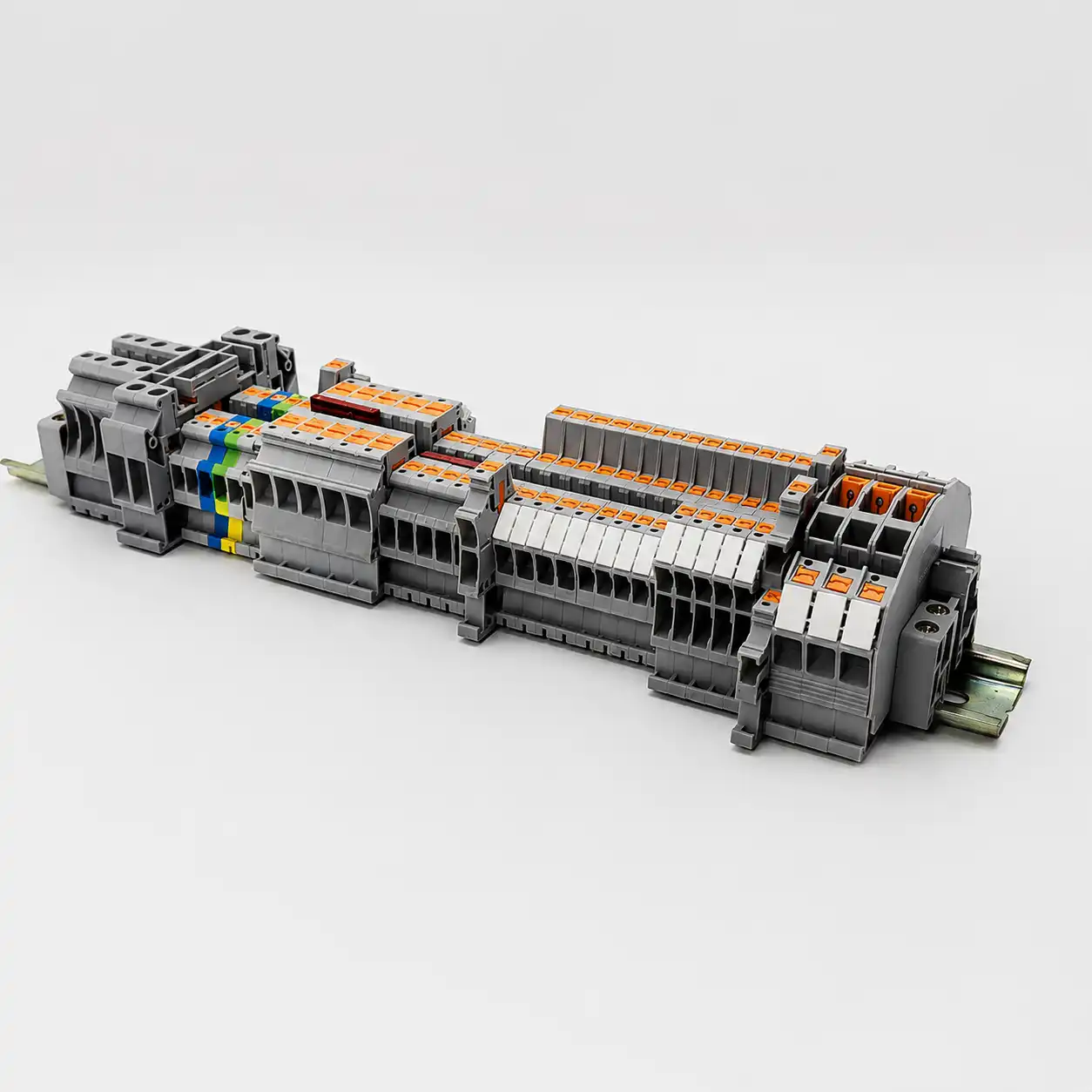
Product-layout scene only; no model, rating, compliance, or dimension can be inferred from the image. Image: SENTOP. Source page. Rehost as an optimized WebP/AVIF before publication.
Calculate the strip that will actually be built
A rail-space total is useful only when another person can reproduce it from the released line-up, current manufacturer data, and the same enclosure drawing.
Freeze the physical line-up
List each feed-through, PE, fuse, disconnect, test, distribution, multi-level, and fitted spare module in installed order. One physical module is one footprint, regardless of connection count.
Collect installed stack increments
Use the exact SKU drawing, current data sheet, configurator, or assembly drawing. Use “pitch” only when the maker defines it as the installed repeat distance for that module.
Account for real end parts and gaps
Include required end stops, end plates, partitions, spacers, and group boundaries once. Do not add the bounding-box width of a jumper or marker that sits on positions already counted.
Compare worst-case design to usable rail
Use minimum available length and maximum approved stack/allowance assumptions. Keep height, depth, wiring, thermal, EMC, segregation, and service-access checks outside the linear sum unless they create a documented along-rail keep-out.
This article is a planning aid. It does not authorize opening energized equipment, moving terminals, changing bridges, cutting or drilling rail, mounting components, or altering a listed assembly. Qualified personnel must follow the exact product, assembly, site, and electrical safe-work requirements. In U.S. workplaces, 29 CFR 1910.333 governs de-energization, lockout/tagout, verification, and qualified-person work practices where applicable.
Separate the installed stack, the allowance, and the usable rail envelope
The equation is simple; input control is the hard part. Start from a released terminal-strip BOM and physical sequence. A part may be counted inside the stack or deducted from usable length, but never both. Where manufacturer tolerances are unavailable, do not invent them. Use configured assembly data, an approved production allowance, and physical verification.
L_stack,nom = Σ(N_i × s_i) + Σ(M_j × a_j)s_i and a_j are non-overlapping installed increments along the rail for exact terminals and real accessories.
L_design,max = L_stack,nom + T_stack+ + K_axis + R_futureT_stack+ is an approved positive stack/assembly uncertainty budget. K_axis is a documented along-rail keep-out. R_future is named empty capacity, not a universal percentage.
M_min = L_usable,min − L_design,maxRelease the mechanical fit only when M_min ≥ 0 under the approved basis. A nominal zero-margin result should be escalated.
| Input | Use this evidence | Do not substitute |
|---|---|---|
| Physical module count | Released terminal-strip sequence with exact function, part number, quantity, group boundary, and fitted/future status. | Wire count, schematic symbols, connection points, or field-device count. |
| Installed stack increment | Exact product drawing, current data sheet, manufacturer configurator, or approved assembled-strip drawing. | Conductor size, front-view housing width, product-family average, or a distributor thumbnail. |
| Accessory increment | Exact required end bracket, end plate, separator, spacer, blank, or other item that occupies distinct along-rail distance. | The full bounding-box width of a bridge, marker, or cover spanning positions already counted. |
| Documented allowance | Positive stack/assembly uncertainty, named project rule, along-axis keep-out, or defined empty future expansion. Keep these inputs separate. | An unexplained “miscellaneous” line or universal 10/20 percent reserve. |
| Minimum usable length | Actual straight rail envelope after fixed obstructions, owned edge constraints, mounting features, and adverse rail-cut/layout tolerance are handled once. | Cabinet outside width, backplate width, drawing scale, or stock rail purchase length. |
“Rail-axis width” and “pitch” are useful only when the manufacturer defines the value as the installed stack increment for the exact configuration. If a configured strip drawing provides an assembled dimension, prefer that released evidence over a hand-built nominal total.
Build a traceable terminal-strip length
The example starts with hypothetical values. Replace every row with exact part-number data. Add only non-overlapping along-rail increments. The tool does not verify terminal selection, thermal performance, fault duty, PE function, insulation, certification, rail cutting, or enclosure approval.
Nominal stack + positive stack/assembly allowance + along-rail keep-out + empty future reserve ≤ minimum usable rail| Installed line item | Quantity | Increment each (mm) | Line total | Remove |
|---|---|---|---|---|
| 60.0 mm | ||||
| 15.0 mm | ||||
| 12.0 mm | ||||
| 16.0 mm | ||||
| 2.0 mm |
This result is an arithmetic planning output, not a released rail cut or panel approval. Rail-cut and enclosure tolerances that shorten the buildable length belong in the minimum usable rail input; do not hide them inside the positive stack allowance. If exact assembled tolerances, fixed obstructions, or required end-system rules are missing, mark the result “review required” and obtain manufacturer/configurator or approved engineering evidence.
Accessories add length only through the exact installed arrangement
Required end restraints, end plates, partitions, spacers, and blank modules can change the strip footprint. Their quantity and role come from the selected terminal system, not from a generic accessory allowance. A second terminal group on the same rail may need its own boundaries and end hardware.
Bridges, jumpers, markers, and covers often sit on positions already counted. Their catalog bounding-box width is not automatically another line item. Verify their family, pitch, skipped positions, electrical rating, cut-end treatment, partition consequences, and any distinct module they require.
- Always count: each exact installed terminal or functional module at its documented stack increment.
- Count once: every required end stop or bracket using one consistent occupied-versus-usable convention.
- Count when required: end plates, partitions, spacers, blanks, and dedicated marker carriers that occupy distinct rail-axis distance.
- Do not auto-add: bridges, markers, and covers that span positions already present in the sum.
Review end plates, jumpers, markers, and other terminal accessories.
More connections do not automatically mean more rail length
Count the one installed module at its published increment. Verify its extra height, depth, wire entry, test access, labeling, and circuit topology separately.
A spare terminal is a real BOM item
Count its exact module width plus any boundary or marker consequence. Record whether it is unwired, marked, bridged, or held for a defined future circuit.
A blank gap needs an owner and a reason
Record a defined length or install an approved blank/spacer module. Do not let an unexplained percentage hide mechanical retention, future boundaries, or assembly-change requirements.
Required does not mean “approximately negligible”
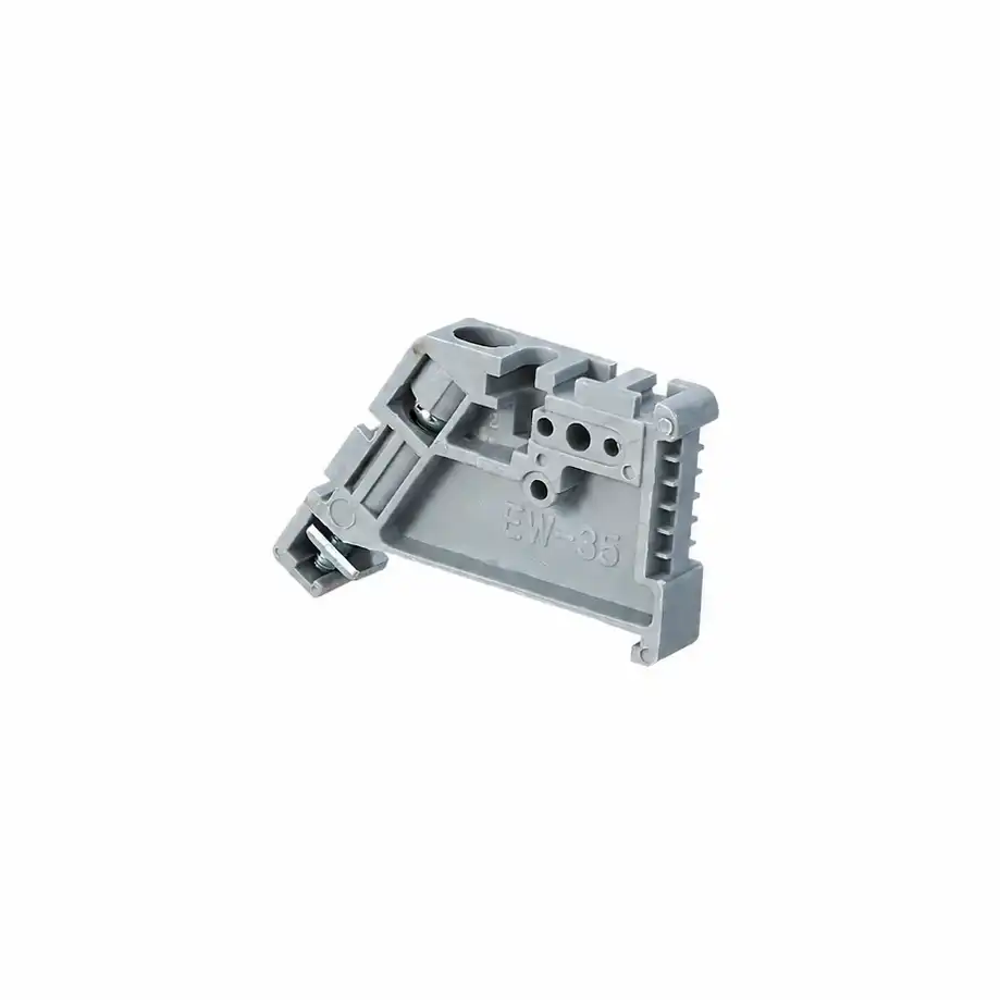
Manufacturer instructions can require one or two end restraints depending on the line-up. Count the exact SKU and quantity once. When a family requires an end plate to close an open side, cover a mixed-interface boundary, provide touch protection, or support separation, include its non-overlapping installed effect as well.
A second terminal group on the same rail can create another end system. Conversely, an enclosure edge must not be assumed to replace a listed end stop unless the exact product and assembly instructions support that arrangement.
Similar terminal blocks can have different stack increments
Manufacturer examples show why 5 mm per terminal is not a release rule. Numbers below are product-specific illustrations, not a mixed-brand BOM or recommendation. Check the current locale-specific data and compatible accessory list before use.
| Official product example | Illustrative published data | Planning lesson |
|---|---|---|
| Phoenix Contact UT 2,5 | Terminal width is listed as 5.2 mm; depth data depend on the selected NS 35 rail condition. Related end-cover and end-bracket items have their own dimensions. | Use width for the along-rail total, but retain the exact rail profile and check the 3-D envelope independently. |
| WAGO TOPJOB S 2002-1201 | The product page lists a 5.2 mm width for this exact terminal. | A matching number across brands does not prove bridge, end-part, conductor, rating, listing, or assembly interchangeability. |
| Weidmüller A2C 2.5 | Product data list a 5.1 mm width; its matching end-plate family has a separate installed dimension. | A 0.1 mm per-position difference becomes meaningful in a long strip. Accessory rows need their own quantity and evidence. |
Product pages can change. Record manufacturer, exact order number, data-sheet/configurator revision, retrieved date, rail profile, and assembly context in the released calculation.
Pass the 3-D and assembly checks before release
A terminal strip can fit along the rail and still interfere with wiring duct, a door, neighboring components, plugs, labels, or service tools. Add a value to the linear equation only when the requirement truly creates a documented along-rail keep-out.
Match the exact mounting interface
Identify the rail part/profile and every terminal, end restraint, and PE component that uses it. A nominal 35 mm label does not complete the compatibility check.
Model the full component envelope
Include rail height, plugs, markers, fuse handles, test points, covers, neighboring equipment, the backplate, and the closed door.
Keep bend, entry, and tool access separate
Use conductor, duct, plug-withdrawal, shield termination, service, and OEM rules. “Leave room for wires” is not a universal millimeter value.
Verify the assembled application
Check current path, bridges, derating, heat, PE/fault duty, creepage, clearance, segregation, EMC, protection, and applicable assembly evidence separately.
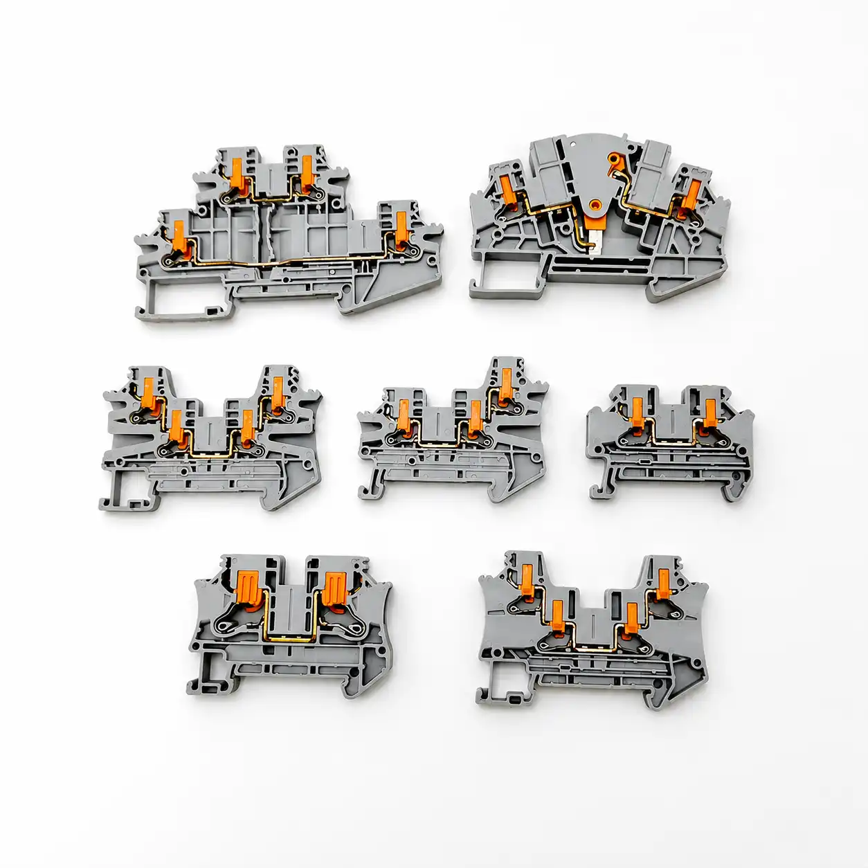
Do not turn non-linear requirements into a hidden width allowance. Wire bend, duct clearance, tool access, door clearance, heat flow, EMC routing, and segregation are separate design inputs. Only a requirement that consumes the along-rail axis belongs in K_axis.
A conductor-grouping or terminal current-temperature derating check is not a space multiplier. A creepage/clearance rule is not a generic empty module. A PE terminal that clips to the rail is not approved by geometry alone.
IEC 61439-1 is used with the applicable assembly product part; a component fit calculation is not assembly verification. In North American equipment, a Recognized Component can have Conditions of Acceptability that remain part of the end-product evaluation.
Use an eight-step rail-space control workflow
The goal is not merely a number. The goal is a terminal-strip drawing, BOM, rail-cut instruction, fit record, and open-issue list that remain tied to the same revision.
Freeze the revision and rail location
Record panel, strip tag, orientation, rail profile, drawing revision, purpose, and whether the calculation is preliminary, quoted, approved, or released.
Build the installed sequence
List exact function, SKU, quantity, group, level, fitted/future status, and boundary parts in physical order.
Collect current manufacturer data
Capture installed stack increment, height, depth, rail compatibility, accessory relationships, and document revision or URL.
Calculate non-overlapping increments
Total terminals and only the accessories that occupy distinct rail-axis distance. Keep bridges and markers from being double counted.
Add named allowances
Apply approved tolerance/production basis, along-rail keep-outs, and future reserve as separate documented inputs.
Derive minimum usable length
Use the actual rail location and fixed obstructions. Assign every end constraint to one side of the fit calculation only.
Run parallel fit and duty checks
Review 3-D envelope, wiring, access, thermal, EMC, segregation, PE, insulation, ratings, and assembly requirements.
Release evidence and open issues
Issue the line-up, BOM, cut drawing, margin, tolerance basis, approvals, reviewer/date, and every unresolved item requiring OEM or engineering review.
Catch the shortcuts that create unbuildable line-ups
A conservative-looking overestimate can still be poor engineering if no one can reproduce it. Replace hidden cushions with named parts, exact evidence, and a controlled margin.
| Shortcut | Why it fails | Better correction |
|---|---|---|
| Terminal count × 5 mm | It ignores functional variants, multi-level footprints, end systems, accessories, and cross-brand variation. | Use the exact physical sequence and installed increment of each SKU. |
| Use width/pitch without checking its definition | A catalog dimension may be a bounding box rather than the assembled repeat increment. | Confirm the dimension axis and installed configuration or use configurator/assembly output. |
| Add every accessory width | Jumpers, markers, and covers can overlap positions already counted. | Add only distinct along-rail increments; verify accessory consequences separately. |
| Use nominal fit with zero margin | Tolerances, cut variation, installed condition, and minimum usable length are not represented. | Use maximum design requirement versus minimum usable envelope and an approved basis. |
| Add a universal 10 or 20 percent reserve | The value can be too small, too large, or impossible to defend later. | Reserve actual fitted positions or a named project/customer expansion length. |
| Treat rail fit as complete approval | Geometry does not verify ratings, thermal behavior, PE/fault function, insulation, accessories, or certification. | Run each applicable electrical, thermal, mechanical, and assembly check in its own domain. |
Send the line-up, not just a terminal count
SENTOP can review terminal families, accessory relationships, dimensions, labels, grouping, and supply requirements when the request includes the actual physical and market context. Final panel engineering and approval remain with the responsible project team.
DIN rail space calculation FAQ
Can I multiply the number of terminals by 5 mm?
Not for a released design. A 5 mm assumption may support an early sketch, but terminal functions, levels, families, and accessories vary. Build the physical sequence and use each exact model's manufacturer-defined installed stack increment.
Do end stops need to be included in DIN rail length?
The exact required end restraints must be accounted for once. Include them in the occupied stack or deduct their owned footprint when deriving usable length. Do not omit them or count them on both sides.
Do end plates always add to the terminal-strip length?
No universal rule applies. Include a required end plate, partition, or separator according to the exact family instructions and its installed stack effect. Its thickness and role can differ by system and position.
Does a multi-level terminal take twice the rail space?
Not automatically. A multi-level module can serve several circuits while occupying one documented stack increment. Count that physical module once, then check its height, depth, access, labeling, and circuit topology separately.
Do jumpers and bridges add DIN rail length?
Often they do not, because they span terminal positions already counted. Verify exact compatibility, pitch, rating, skipped positions, partitions, and cut-end treatment. Add length only for a distinct module or keep-out shown by the approved arrangement.
How much future DIN rail space should I leave?
There is no universal percentage. Reserve actual fitted terminals or a documented expansion length with a stated reason, owner, and boundary plan. Keep an approved tolerance or production allowance separate from future capacity.
Is every 35 mm DIN rail equivalent for terminal-block fit?
No. Identify the exact rail profile, height, material or finish, and product compatibility. A terminal may fit mechanically while producing a different depth envelope; PE and assembly functions require their own documented verification.
Can I release a terminal strip when the nominal margin is zero?
A zero-margin nominal fit is not robust release evidence. Compare the maximum approved design requirement with the minimum usable rail envelope, including the controlled tolerance or production basis. Escalate missing data rather than assuming the parts will compress into place.
Does a rail-space calculation prove electrical acceptability?
No. It is a mechanical layout input. Conductor acceptance, current path, bridges, temperature, PE or fault duty, voltage, insulation, protection, assembly conditions, and approvals must be checked under their own applicable data and procedures.
Standards and manufacturer evidence
Standards define scope and test frameworks; they do not supply a universal terminal width, enclosure margin, or accessory allowance. Product dimensions and arrangement rules remain exact-model and exact-system evidence.
- IEC 60715:2017. Dimensions of low-voltage switchgear and controlgear - standardized mounting on rails. Mounting-rail interface reference.
- IEC 60947-7-1:2025. Terminal blocks for copper conductors. Support-mounted terminal-block scope; exact product data still govern.
- IEC 60947-7-2:2009 and IEC 60947-7-3:2009. Protective-conductor terminal blocks and fuse terminal blocks. Function-specific scope for PE and defined fuse-terminal applications.
- IEC 61439-1:2020 and IEC 61439-2:2020. Assembly general rules used with the applicable product part, such as power switchgear and controlgear assemblies.
- IEC 60664-1:2020+AMD1:2025 CSV. Insulation coordination within low-voltage supply systems. Current consolidated IEC edition 3.1; it does not create a generic blank-module allowance.
- WAGO Smart Designer. Terminal strip properties. Planning-tool example that treats rail length and projection as explicit layout data.
- UL Solutions. Connector and terminal-block certification services. Product certification scope; it does not approve an end-product arrangement by dimension alone.
- UL Solutions. Component Recognition and Conditions of Acceptability. Conditions remain relevant in the evaluated end product.
- Phoenix Contact. UT 2,5 product data. Example of exact-model width and rail-dependent depth data.
- WAGO. Interconnection technology FAQ. Exact terminal-family rules can require end stops, end plates, or separation components.
- WAGO. TOPJOB S 2002-1201 product data. Exact-model width example.
- Weidmüller. A2C 2.5 product data. Exact-model width, rail, and envelope example.
- OSHA. 29 CFR 1910.333. U.S. electrical safe-work, de-energization, verification, and qualified-person boundary.
Turn the terminal-strip drawing into a reviewable BOM
Send the exact physical sequence, rail profile, component data, accessory list, usable envelope, allowance basis, quantity, target market, and documentation needs. SENTOP can support model matching and supply coordination without treating a dimensional fit as complete panel approval.
