
Barrier vs DIN Rail Terminal Blocks: 7 Key Differences
Choose a DIN rail terminal system when modular functions, organized expansion and a shared accessory ecosystem drive the panel design. Choose a barrier strip when the equipment needs a direct panel or PCB interface, a fixed pole layout, or specific screw, stud or lug hardware. Current and vibration are not category shortcuts—both must be verified on the exact product.
The real decision is complete connection system versus complete connection system—not “screw versus spring” or “high current versus low current.”
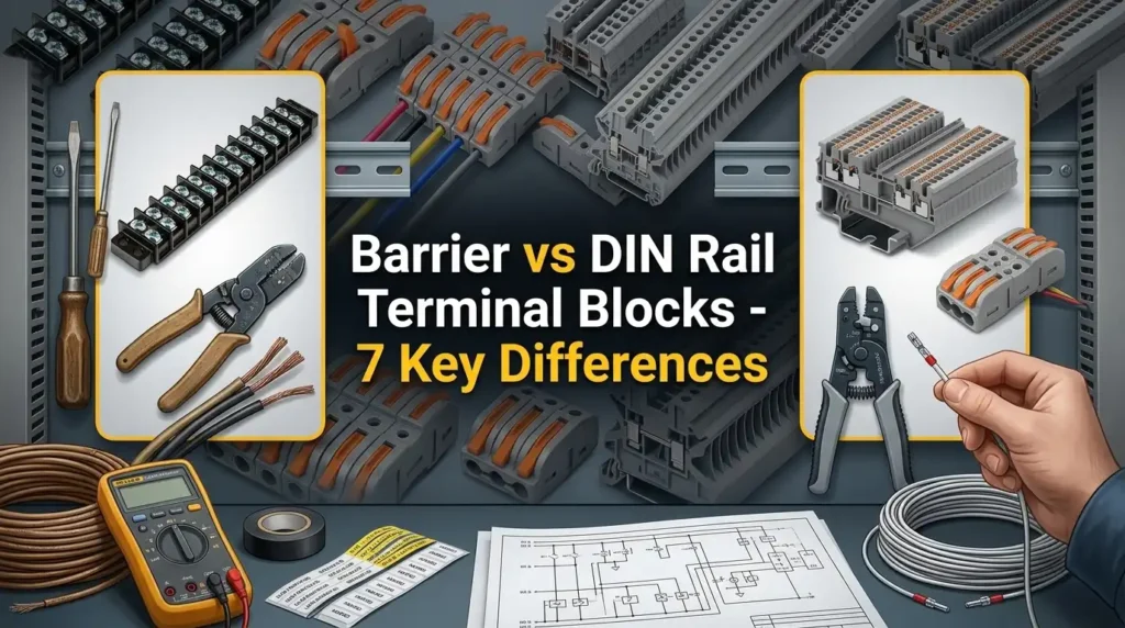
Choose your starting point
The best option is the one that matches the conductor interface, mounting geometry, circuit functions, maintenance method and qualification evidence as one installed assembly.
Fixed equipment interface
Useful when the drawing calls for direct panel or PCB mounting, a defined pole strip, clear physical barriers, or model-approved screw, quick-connect, ring or fork hardware.
Modular terminal strip
Useful when feed-through, PE, fuse, disconnect, test, marker and bridge functions must be arranged and changed within one documented rail system.
Hybrid field interface
A barrier strip can receive a field harness while DIN rail blocks organize internal controls—provided the full equipment design preserves ratings, grounding and separation.
Do not award either category a universal win for current, voltage, vibration, IP protection, wiring speed or cost. Compare exact part numbers and complete BOMs.
Barrier and DIN rail describe different architectures
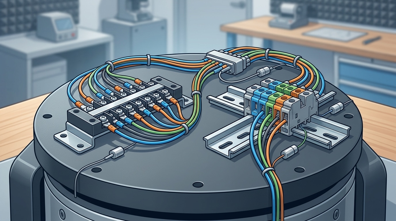
A barrier strip is identified by insulating walls between terminal positions. A DIN rail terminal block is identified by its rail-mounting system. Either description alone tells you very little about current capacity, conductor range or vibration performance.
Fixed strip or board interface
Barrier families may be panel-mounted, PCB-mounted, single-row or double-row. Depending on the model, the connection can accept bare wire, wire clamps, binding hardware, quick-connect tabs, solder pins, ring terminals or fork terminals.
Modular rail-mounted system
DIN rail families can use screw, spring-cage, push-in, lever or bolt connections. Individual modules can provide feed-through, PE, fuse, disconnect, test, diode, distribution and multi-level functions.
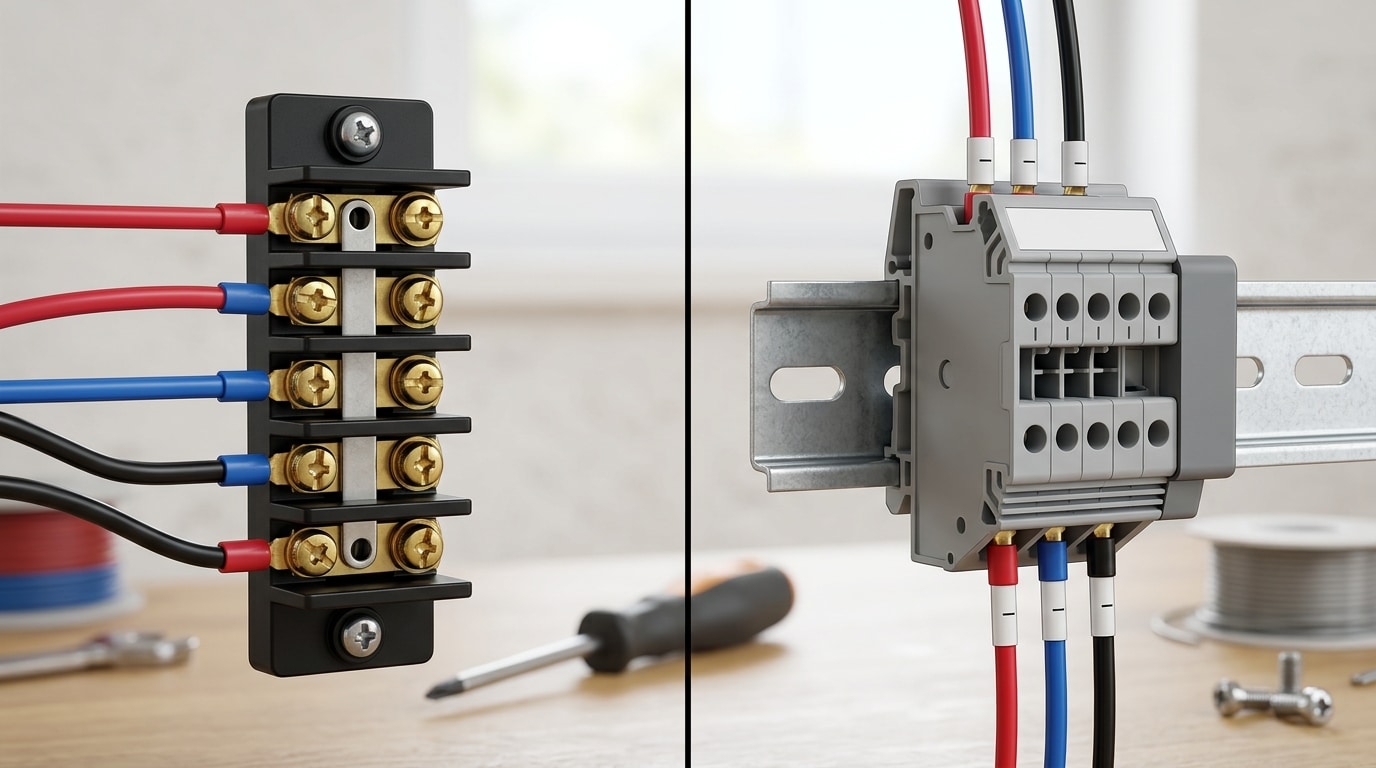
Many DIN rail terminals use screws, and not every barrier strip requires a ring lug. Connection technology and mounting architecture are two separate selection decisions.
Barrier terminal block vs DIN rail terminal block: 7 differences
The table gives a defensible starting point without inventing universal amperage, voltage, pitch, price or installation-time ranges.
| Decision factor | Barrier block | DIN rail block | What actually decides |
|---|---|---|---|
| 1. Mounting | Commonly panel or PCB mounted; often a fixed multi-pole body | Individual modules attach to a compatible standardized rail | Hole pattern, rail profile, retention, end stops and available geometry |
| 2. Termination | Often screw or stud; bare-wire and hardware options vary | Screw, spring, push-in, lever and bolt families are available | Conductor type, preparation, hardware stack and installation instructions |
| 3. Density/functions | Pitch and pole count are built into the selected strip | Modules, multilevel versions and functional blocks share a rail ecosystem | Complete installed BOM, wiring bend space and technician access |
| 4. Ratings | Wide model-dependent electrical range | Wide model-dependent electrical range | Exact datasheet and certification conditions—not mounting category |
| 5. Environment | Performance depends on lug/clamp, hardware, body and mounting | Performance depends on clamp, rail retention, end stops and accessories | Product-specific shock, vibration, corrosion and temperature evidence |
| 6. Service | Directly visible pole hardware; fixed strip replacement may affect several poles | Strong marking, test and functional options; modules remain system-dependent | De-energized work method, access, spares and documentation |
| 7. Cost/compliance | Add lugs, crimping, drilling, covers and marking | Add rail, end stops, end plates, bridges, partitions and marking | Total installed cost and end-equipment acceptance |
Official product ranges show substantial overlap. Treat any “barrier equals high current” or “DIN equals low current” shortcut as a reason to reopen the exact datasheets.
How the seven differences change the design
Mounting and panel architecture
Fixed footprint versus configurable rail
Panel-mounted barrier strips normally use end ears or mounting holes, while PCB versions use solder pins and a board footprint. That makes the hole pattern, pole count, wire-entry direction and cover envelope part of the equipment design. A replacement must match the product drawing—not just the number of screws.
DIN rail blocks attach to a compatible rail and are secured as an assembly with the specified end stops or brackets. IEC 60715 defines dimensional and functional requirements for compatible mounting on standardized rails; it does not provide the terminal’s electrical rating or automatically establish a PE function. Confirm the exact rail profile, material/finish, terminal foot, orientation and retaining hardware.
Conductor termination and preparation
Hardware choice matters more than the label
Barrier strips often use binding-head screws, wire clamps or studs, but the accepted conductor preparation varies. Some products are designed for bare conductors; others support ring or fork hardware, quick-connect tabs or solder terminations. A ring lug is only valid when the screw/stud size, lug barrel, tongue geometry, material, plating and stacking order are approved for the connection.
DIN rail terminals cover several connection technologies. Screw-clamp versions require the exact torque and conductor preparation. Spring and push-in versions require the stated conductor type, cross-section, strip length and ferrule policy. Bolt-connected rail terminals such as the Phoenix Contact RT 5 also show why ring or fork hardware is not exclusive to barrier strips. Do not assume “tool-free” means every stranded conductor can be inserted without an operating tool or ferrule.
Instead of asking which category wires faster, ask how the approved conductor arrives—bare, ferruled, ultrasonically bonded, ring-lugged or fork-lugged—and which tools and inspection steps that preparation requires.
Circuit density and functional range
Compare complete installed footprints
A barrier strip’s pitch, row arrangement and number of positions are normally fixed by the selected part. This can produce a clear, robust field-landing interface, but adding a circuit may require another strip, more drilling or a different pole count.
DIN rail systems are assembled from individual or multi-level modules. Feed-through, PE, fuse, disconnect, test and distribution functions can be placed in sequence with model-matched bridges and markers. That modularity is valuable in PLC and control cabinets, but every end plate, partition and functional module consumes real space.
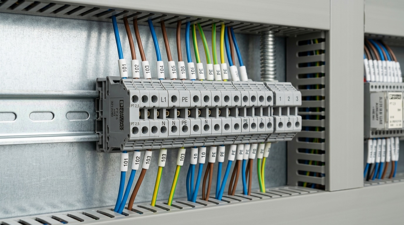
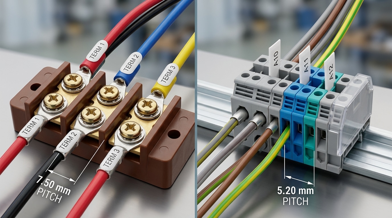
Total the installed length of every terminal and accessory, then check height, depth, wire-duct clearance, conductor bend radius, marker visibility and tool access. Report the result for that design only.
Current, voltage and conductor ratings
Architecture is not an ampacity class
Both barrier and DIN rail families span low-energy signals, control circuits and power connections. The approved current depends on the conductive path, clamp or hardware, conductor size and type, ambient conditions, adjacent loading and the applicable certification system. The voltage rating depends on insulation design, spacing, pollution conditions, overvoltage category and product evaluation.
IEC 60947-7-1:2025 covers industrial support-mounted terminal blocks for copper conductors within its stated scope, but the scope limit is not a product rating. Likewise, UL 1059 states that compliance does not by itself assure suitability in an end product. Read the exact certification record, rating table and conditions of acceptability.
Jumpers, quick-connect tabs, covers, disconnect elements and lugs may carry their own ratings. The lowest applicable limit controls the assembled connection.
Vibration, shock and environment
There is no automatic winner
A properly qualified ring-lug barrier assembly can provide strong mechanical retention. A properly qualified spring-pressure DIN rail assembly can also perform in demanding vibration applications. The outcome depends on the clamping principle, conductor preparation, hardware, strain relief, terminal body, rail or panel mounting, end stops, accessory configuration and test severity.
IEC 60068-2-6 provides a sinusoidal vibration test method; the relevant specification selects the severity and acceptance criteria. SAE J1455 describes environmental practices for heavy-duty vehicle electronic equipment. Neither source creates a universal acceleration threshold at which every barrier strip beats every rail-mounted block. Product pages such as the Phoenix Contact PT 2.5 publish model-specific test data and approvals; that evidence applies to the documented configuration, not every DIN rail terminal.
Ingress protection and touch protection are also product- and enclosure-specific. Do not label an entire mounting category “IP20” or assume that a cover upgrades the complete equipment to an enclosure IP rating.
Serviceability, testing and expansion
Design around the maintenance task
Barrier strips can provide clear visual separation and direct access to screw or stud hardware, which may suit a field harness or legacy equipment interface. However, a fixed multi-pole body can make replacement or expansion more disruptive, and exposed hardware may need a model-matched cover.
DIN rail systems offer extensive marker channels, test points, disconnects, fuses and plug-in functions. Individual modules can be added when spare rail and compatible accessories are planned. Yet the assembly still requires safe de-energization, end-stop control, correct module ordering and sufficient space to operate tools or release mechanisms.
Apply the manufacturer’s specified torque and maintenance instructions. A universal “re-torque after 24 hours” rule can be inappropriate and should not replace the exact product documentation.
Total installed cost and compliance
Price per pole is an incomplete comparison
A barrier solution may add panel drilling, lug procurement, crimping, hardware control, covers and fixed-strip marking. A DIN solution may add rail cutting and mounting, end stops, end plates, partitions, jumpers, markers and spare rail allowance. Labor depends on the conductor preparation, production volume, tools, test method and operator training—not on the category name alone.
Build two complete BOMs and compare purchased parts, preparation time, assembly time, inspection, testing, enclosure space, approved alternates and lifecycle spares. Then check conductor material and temperature limits, component certification, spacing and insulation conditions, SCCR-related requirements, and the rules of the complete panel, machine, appliance, vehicle or marine installation. A recognized terminal component does not certify the end product.
The comparison should end with two traceable assemblies: exact part numbers, conductor preparation, mounting hardware, accessories, markers, ratings, standards evidence and sample-test plan.
When barrier, DIN rail or a hybrid design makes sense
Use these as starting routes, then apply the electrical, mechanical and end-equipment checks above.
Fixed landing or board interface
- Existing panel footprint or PCB pin layout must be preserved.
- The approved field interface uses defined screw, stud, ring, fork or quick-connect hardware.
- A fixed pole strip and barrier/cover arrangement improves inspection.
- The exact product has the environmental and electrical evidence required.
Modular cabinet wiring
- PLC I/O and control wiring need repeatable marking and commoning.
- Feed-through, PE, fuse, disconnect or test functions share one terminal plan.
- Future expansion and model-matched accessories are planned.
- The rail, end stops and complete terminal family meet the project requirements.
Field interface plus controls
- A barrier strip receives an equipment harness or lugged field cable.
- DIN rail modules organize internal signal, control and functional circuits.
- A dedicated power terminal feeds a separate modular control strip.
- The complete design preserves grounding, circuit separation and documentation.
| Scenario | Starting point | Reason | Do not skip |
|---|---|---|---|
| PLC/control panel | DIN rail | Modular functions, bridges, markers and test options | Exact rail system, functional ratings and service clearance |
| Legacy fixed strip | Barrier or engineered conversion | Existing holes, cover, harness and pole sequence may control | Drawing comparison and impact on equipment approval |
| Lugged field entry | Barrier or bolt-type terminal | Defined hardware interface may suit the incoming cable | Lug/stud compatibility, torque, cover and strain relief |
| High-current input | Evaluate both | Both architectures include power-oriented products | Fault duty, temperature, conductor, cover and certification |
| Mobile or marine equipment | Evaluate qualified assemblies | Project environment and wiring rules control the choice | Exact vibration, corrosion, fire, mounting and end-equipment evidence |
| Mixed field/control panel | Hybrid | Each interface can use the architecture that fits its job | Separation, PE, overcurrent protection and terminal plan |
Choose from the circuit outward, not the catalog inward
A defensible comparison starts with the installed conductors and ends with a tested, documented BOM.
Map every circuit
Record function, potential, AC/DC, current, voltage, fault condition, required isolation and PE role.
Define conductor preparation
List wire size/type and whether it arrives bare, ferruled, ultrasonically bonded, ring-lugged or fork-lugged.
Model the mounting geometry
Compare hole pattern or PCB footprint against rail profile, end stops, block order, duct and bend clearance.
Verify electrical data
Check exact ratings, accessories, adjacent loading, spacing, insulation conditions and end-product requirements.
Verify the environment
Match temperature, vibration, shock, humidity, corrosion, altitude, contamination and enclosure conditions.
Build and test the BOM
Include all hardware, markers and tools; approve a sample in representative mechanical, thermal and service conditions.
Replacing a barrier strip with DIN rail terminals—or the reverse—can change mounting, spacing, conductor preparation, touch protection, fault behavior, markings and equipment certification. Review the change formally.
Validate the complete connection system
Use the exact product drawing and installation instructions. Similar-looking screws, lugs, jumpers, covers and end stops are not automatically interchangeable.
Barrier assembly checks
- Mounting-hole or PCB footprint and body support
- Approved screw/stud and hardware stack order
- Lug tongue, barrel, conductor and crimp tooling
- Specified torque, cover and pole marking
- Wire pull, strain relief and adjacent clearance
DIN rail assembly checks
- Compatible rail profile, terminal foot and orientation
- End stops, end plates, partitions and covers
- Jumper pattern and jumper-specific rating
- PE terminal and rail/enclosure bonding design
- Marker visibility, test access and spare positions
Check representative conductor sizes, expected load and temperature, wire forces, mounting retention, dielectric/continuity requirements, covers, marking and the actual maintenance procedure before bulk release.
Send the interface drawing, not only “barrier” or “DIN.”
SENTOP can compare barrier and DIN rail models from a part number, photo, drawing, terminal list or BOM. Include the conductor preparation and mounting geometry so the accessories can be matched as one assembly.
Move from architecture to exact models
Review both product families, then complete the terminal strip with compatible mounting and accessory parts.
Barrier Terminal Blocks
Explore high-current, PCB-mount, dual-row and screw barrier product directions.
View barrier blocks → Modular cabinet optionsDIN Rail Terminal Blocks
Compare feed-through, distribution, push-in, spring and other rail-mounted terminal families.
View DIN rail blocks → Connection technologyScrew Terminal Blocks
Separate the screw-clamp decision from the mounting decision across barrier and DIN rail series.
Explore screw types → Complete the assemblyTerminal Block Accessories
Plan model-matched end plates, brackets, bridges, markers, partitions and covers.
Choose accessories →Complete the selection process
Barrier vs DIN rail terminal block FAQ
Which is better: a barrier terminal block or a DIN rail terminal block?
Neither is universally better. Barrier strips are often a strong starting point for fixed panel or PCB interfaces and defined screw or lug hardware. DIN rail systems are often a strong starting point for modular cabinet wiring, functional blocks, marking and expansion. The exact circuit and qualification decide.
Are barrier terminal blocks always rated for more current?
No. Both barrier and DIN rail product families include signal, control and power models. Use the exact datasheet and certification record for the conductor, ambient conditions, adjacent loading, accessories and end equipment; mounting style is not a current rating.
Are DIN rail terminal blocks suitable for vibration?
They can be when the exact terminal, connection technology, rail, end stops, accessories, conductor preparation and mounting configuration have suitable test evidence. A barrier strip is not automatically superior, and a generic vibration standard does not qualify every product.
Do all barrier terminal blocks require ring terminals?
No. Depending on the model, barrier strips may accept bare wire through a wire clamp, binding hardware, ring or fork terminals, quick-connect tabs, solder pins or other terminations. Follow the exact product drawing and approved hardware.
Can barrier and DIN rail terminal blocks be used in the same panel?
Yes, when the complete panel design permits it. A barrier strip may serve a field or equipment interface while DIN rail blocks organize internal controls. Verify circuit separation, protective earthing, overcurrent protection, ratings, access, markings and end-product compliance.
Does IEC 60715 certify a DIN rail terminal block's electrical performance?
No. IEC 60715 addresses dimensional and functional requirements for compatible mechanical mounting on standardized rails. Electrical performance and protective-earth functions are covered by relevant product standards, exact product data and the end-equipment requirements.
Standards and manufacturer references
Use the edition required by the project and the exact manufacturer documentation for the selected part number.
- IEC 60715:2017 — standardized rail mounting dimensions and functional compatibility.
- IEC 60947-7-1:2025 — industrial terminal blocks for copper conductors within its stated scope.
- ANSI/UL 1059, 6th edition — terminal block scope and end-product suitability limitation.
- IEC 60068-2-6:2007 — sinusoidal vibration test method.
- IEC 60529, consolidated edition 2.2 — enclosure protection classification expressed by the IP Code.
- SAE J1455_201703 — environmental practices for heavy-duty vehicle electronic equipment.
- Eaton terminal block selection white paper — circuit, footprint, conductor and application-test considerations.
- TE Connectivity barrier strip overview — barrier styles, mounting and termination options.
- Eaton TB300-06B example — a model-specific panel-mounted barrier terminal specification.
- WAGO rail-mount terminal block overview — modular functions, connection technologies and high-current examples.
- Phoenix Contact RT 5 — model-specific DIN rail bolt connection for ring and fork cable lugs.
- Phoenix Contact PT 2.5 — model-specific ratings, vibration/shock test data and approvals for a push-in rail terminal.
