
Ground vs Standard Terminal Blocks: Key Differences and When to Use Each
Use a protective conductor terminal block when the approved design requires the conductor to connect through a compatible fixing support into the protective bonding circuit. Use a standard feed-through terminal block when the circuit must pass between conductors while remaining isolated from the rail. Choose by conductor function and the verified current path—not by housing color, wire gauge or rail mounting alone.
The terminal, rail profile and finish, rail joints, bonding conductors, enclosure and end-equipment test plan must form one documented protective bonding system.
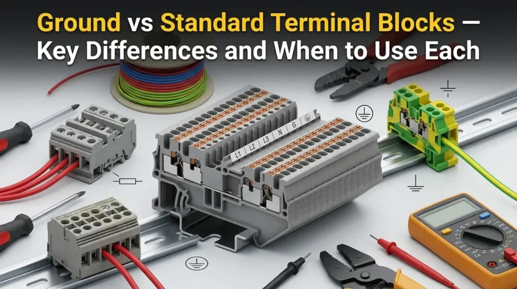
Select the required electrical function
The safest shortcut is not “green-yellow versus gray.” Trace what the conductor must do, determine whether the fixing support is part of the protective circuit, and then approve the exact terminal-and-rail combination.
Protective conductor to an evaluated support
The conductor must join the protective bonding circuit through a rail or other fixing support, and the exact protective conductor terminal block is evaluated for that function.
Isolated wire-to-wire circuit connection
Line, control, signal or a separately managed neutral path must continue through a current bar without becoming electrically connected to the mounting rail.
PE, FE, shield, neutral or PEN is unclear
Do not guess from color or labels. Resolve the schematic function, applicable equipment standard, manufacturer instructions and required bonding point before selecting hardware.
Color helps a technician identify a function; the catalog classification, approved mounting support and electrical verification establish the function.
The defining difference is the connection to the fixing support
In this guide, “ground terminal block” means a rail-mounted protective conductor terminal block (PCTB) whose evaluated function includes an electrical and mechanical connection from the protective conductor to a compatible fixing support. A standard feed-through terminal connects conductors to each other and remains insulated from that support.
Protective bonding function
The clamping unit connects the PE conductor to a conductive terminal foot or contact. The foot engages the approved support, which must then be integrated into the equipment’s verified protective bonding circuit.
Functional circuit continuity
An internal current bar connects the conductor entries while the housing and mounting foot isolate that potential from the rail. Its current, voltage and conductor data are model-specific.

IEC 60715 addresses compatible mechanical mounting on standardized rails. It explicitly leaves the rail’s protective-earthing electrical function to the relevant product standard and complete application.
Ground vs standard terminal block differences at a glance
| Decision factor | Ground / PE terminal block | Standard feed-through terminal block | Evidence to check |
|---|---|---|---|
| Primary function | Protective conductor connection to an evaluated fixing support | Electrical connection between circuit conductors | Schematic designation and exact product classification |
| Rail relationship | Conductive foot or support contact is part of the intended PE path | Current bar is insulated from the rail | Compatible rail profile, material/finish and installation instructions |
| Normal operation | Not intended as a routine load-current path; must meet protective-circuit requirements | Carries the specified load, control or signal current | End-equipment circuit analysis and product data |
| Connection technology | Screw, spring or push-in families may be available | Screw, spring, push-in and other families may be available | Allowed conductor, preparation, strip length, torque or operating method |
| Identification | PE classification and applicable green-yellow/PE identification | Function markers and color selected for the actual circuit | Current marking standard, product label and terminal plan |
| Rating focus | Conductor range, fixing support and protective short-time withstand/test evidence | Rated current/voltage, conductor range, insulation and short-time/SCCR conditions | Datasheet plus IEC/UL certification record and conditions |
| Critical misuse | Using it for an energized functional conductor can bond that potential to exposed conductive parts | Using it while expecting rail bonding leaves the intended rail connection absent | Continuity and functional tests against the approved schematic |
There is no useful category-wide table of “typical” voltage, current, contact resistance, torque or wire size. The limits in a standard’s scope are not the default rating of every terminal, and accessories or end-equipment conditions can narrow the usable values.
Follow the conductor path through the complete assembly
How a protective conductor terminal works
Conductor-to-support connection with a safety function
IEC 60947-7-2 describes protective conductor terminal blocks that form an electrical and mechanical connection between copper conductors and a fixing support. A rail-mounted PE terminal therefore has two interfaces to approve: the conductor-to-clamp connection and the terminal-to-support connection.
The fixing support is only one part of the path. Rail sections, joints, fasteners, bonding conductors, the enclosure and the connection back to the system bonding point must be designed so the protective device and end-equipment safety concept work as intended.
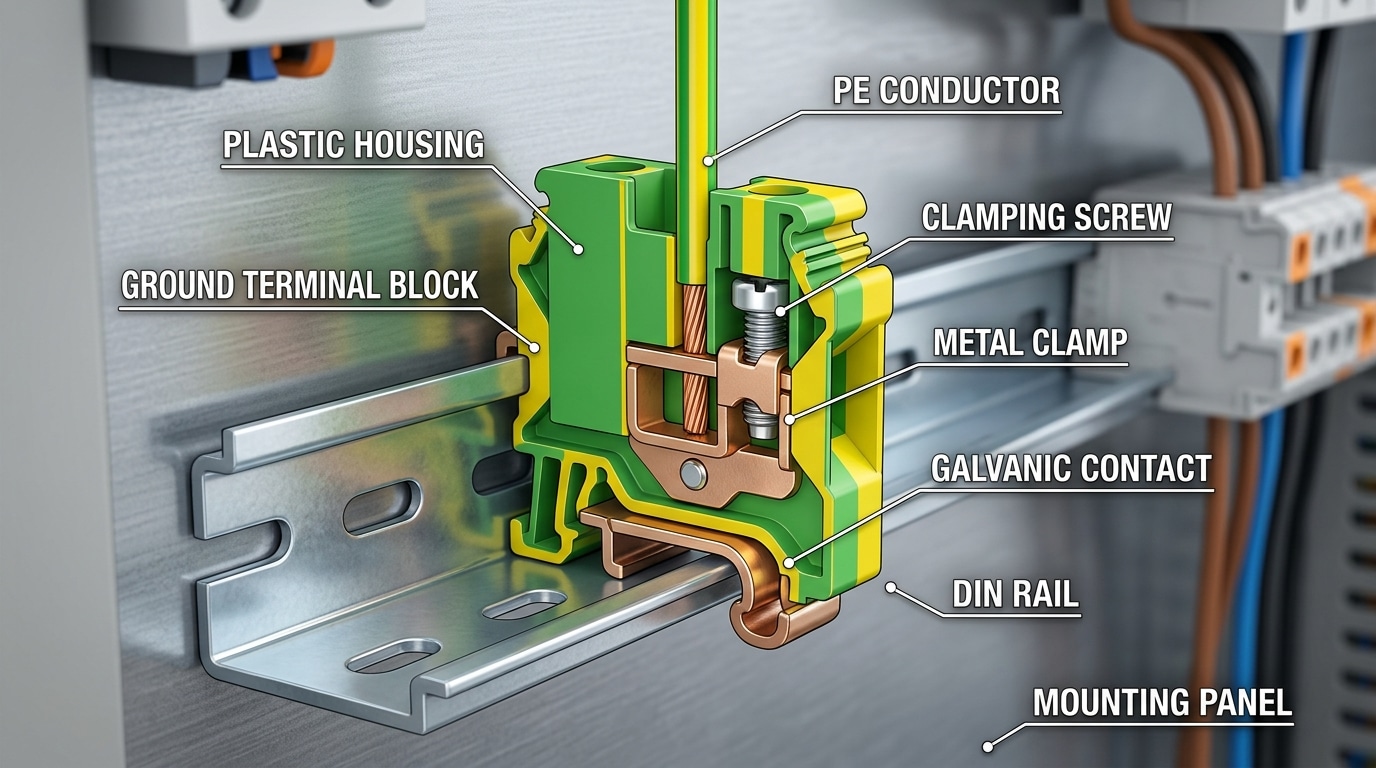
The Phoenix Contact PT 2.5-PE product record identifies a grounding foot, compatible rail types, conductor data and approvals for that specific PE terminal. Use the equivalent evidence for the model being purchased.
How a standard feed-through terminal works
Wire-to-wire continuity with rail isolation
A feed-through terminal places its conductor entries on one internal potential through a current bar. Its housing and rail foot keep that potential electrically separated from the fixing support. This is appropriate for circuit conductors that must be routed, distributed or tested without becoming bonded to the rail.
“Standard” does not mean one construction. Feed-through families can be single-level, multi-level or multi-conductor and can use screw, spring or push-in connections. Disconnect, test and functional versions add another component to the current path. Every variation changes the data and accessories to verify.

A product named for 2.5 mm² may publish a wider connection range for particular conductor types. Only the exact table for that part number tells you what can be inserted and under which conditions.
Protective earth, neutral, functional earth and shield are not interchangeable
The word “ground” is often used for several different functions. Resolve the schematic designation before choosing a terminal or deciding where the rail belongs electrically.
Safety-related protective path
Connects exposed conductive parts into the protective bonding system so fault protection can operate as designed. PE is not a routine load-current conductor.
Current-carrying circuit conductor
Normally remains isolated from PE downstream of the defined system bonding point. It needs a terminal arrangement approved for the system—not a PE rail contact by default.
Operational or EMC reference
Supports equipment function, noise control or a reference potential. FE identification and connection follow the equipment design and cannot replace a required PE connection.
High-frequency interference path
May use a shield clamp, chassis contact, functional earth or another arrangement specified by the equipment manufacturer. Do not route every shield drain through a PE terminal by habit.
IEC 60445:2021 with Amendment 1:2026 addresses identification of equipment terminals, conductor terminations and designated conductors. It is the current IEC reference to consult instead of the withdrawn IEC 60446. Green-yellow identification is an important PE cue in IEC-based systems, but it is not a substitute for the PE symbol, catalog classification and electrical verification.

A combined protective-earth-and-neutral function is limited by the applicable system and conductor rules. Do not turn an ordinary PE or neutral terminal into a PEN point without a formally designed and compliant arrangement.
Approve the rail, conductor and terminal as one system
DIN rail and fixing-support compatibility
Mechanical fit does not establish protective performance
Confirm the exact rail profile named by the terminal manufacturer, such as the applicable 35 mm top-hat variation, and check rail material, finish, thickness, orientation and environmental suitability. A plastic rail, an incompatible coating or an unapproved support cannot be assumed to provide the terminal’s evaluated PE interface.
Also trace electrical continuity across cut rail sections, mechanical joints, hinged plates, enclosure panels and bonding conductors. An end stop keeps terminals in position; it does not automatically create an electrical bond. The assembly drawing should show how the fixing support enters the protective bonding circuit.
Use the rail and surface condition specified for the terminal system. Do not sand, scrape or machine a coating or plating unless the manufacturer’s instructions or approved equipment design requires that treatment; an approved contact can be designed for a stated surface without field modification.
Ratings, conductor preparation and accessories
Part-number data controls the connection
For a standard feed-through terminal, check the rated current and voltage in the correct certification system, conductor material and class, cross-section, ambient conditions, adjacent loading, pollution/insulation conditions and the limits of jumpers or disconnect elements. For a PCTB, check the allowed conductor and support, protective-conductor short-time withstand evidence, terminal marking and conditions stated in the certification record.
Screw connections require the exact torque and tool stated for the model. Spring and push-in connections require the specified operating method, strip length and conductor preparation. Ferrules can be required, permitted, restricted or unnecessary depending on the conductor and terminal; “always use ferrules” is not a valid category rule.
A PE version and a feed-through version can share pitch and connection technology while having different rail contacts, markings, ratings and certifications. Compare the complete order number and drawing.
Use each standard for the question it actually answers
Component standards, installation rules and end-equipment standards overlap, but none of them lets a designer approve a panel from the terminal color alone. Editions adopted by the project or authority can differ by market.
IEC 60947-7-2:2009
Requirements for protective conductor terminal blocks for copper conductors and their connection to a fixing support, within the standard’s stated PE/PEN scope.
IEC 60947-7-1:2025
Requirements for industrial terminal blocks for copper conductors. Its scope limits are not a universal product rating.
IEC 60715:2017
Compatible mounting dimensions and functions for standardized rails. The PE electrical function belongs to the relevant product/application standard.
IEC 60445:2021 + A1:2026
Identification and marking of terminals, terminations and designated conductors, including protective and functional earthing distinctions.
ANSI/UL 1059, 6th edition
Includes protective conductor terminal blocks within its scope and states that component compliance alone does not assure suitability in an end product.
IEC 60204-1 / NFPA 79
End-equipment requirements for machinery include protective bonding and verification. Use the project’s adopted edition and test criteria.
For building or industrial installations, also apply the relevant grounding, bonding and protective-conductor rules, such as IEC 60364-5-54 or the locally adopted electrical code. In the United States, OSHA 1910.304 addresses grounding requirements and OSHA 1910.305 addresses suitable connections and coated surfaces. Neither creates the universal 25 Ω or milliohm terminal thresholds repeated in the original draft.
NFPA 79:2024 Section 18.2 does include a 0.1 Ω acceptance value under one prescribed impedance-measurement method for the completed machine's effective ground-fault current path, with another specified test method also available. That is an end-equipment verification criterion with defined instruments and measuring points—not an IEC 60947-7-2 terminal-contact rating or a universal value for every panel.
Specify the exact product standard/edition or certification category, terminal part number, rail/support, conductor schedule, accessories, destination market, end-equipment standard and required documentation. “Green ground terminal, UL/IEC” is not enough.
Choose the route from the schematic function
These are initial routes for design review. The exact equipment instructions and adopted standards can change the implementation.
Protective bonding conductor
- Equipment frame or machine protective conductor
- Rail is deliberately part of the PE network
- Exact PCTB and support are evaluated together
- Protective continuity is tested by the required method
Power, control or signal circuit
- Potential must remain isolated from the rail
- Terminal carries the circuit’s operating current
- Voltage, conductor and accessory ratings control
- Markers and test functions match the terminal plan
Neutral, FE, shield, SPD or PEN
- “Ground” has more than one possible meaning
- Equipment instructions define the termination path
- Safety PE and EMC functions remain distinguishable
- No connection is approved by color alone
| Scenario | Starting route | Why | Required verification |
|---|---|---|---|
| Motor or machine frame PE | PCTB or approved PE bar | Protective conductor must join the bonding circuit | Terminal/support system, conductor sizing and end-equipment continuity test |
| 24 VDC PLC signal | Standard feed-through | Signal must pass between conductors and stay isolated from rail | Current/voltage, conductor, jumper, marker and test-point data |
| Neutral conductor | Isolated neutral arrangement | Neutral is a current-carrying circuit conductor, not interchangeable with PE | System bonding point, disconnect/test requirements and local rules |
| Cable shield or FE | Equipment-defined shield/FE path | EMC function can require chassis, shield bar, FE or another termination | Drive/PLC/instrument instructions and EMC design |
| SPD protective connection | SPD-defined PE/bonding path | Lead routing and terminal arrangement affect the protective function | SPD manual, conductor route, overcurrent arrangement and panel standard |
| Mixed L/N/PE terminal strip | Certified coordinated system | Multiple potentials can share a rail while retaining distinct functions | Module order, end plates/partitions, rail bonding, marking and spacing |
| Legacy rail with unknown finish | Stop and inspect | Mechanical fit does not prove an evaluated PE contact | Part numbers, rail material/finish, drawings and representative test plan |
Turn the selected part into a traceable connection
Work on de-energized equipment under the site’s safe-work procedure and use qualified personnel. The steps below define the documentation flow; the product and end-equipment instructions define the actual tools, values and tests.
Classify the conductor
Mark PE, N, FE, shield, line, control and signal functions on the schematic before selecting terminal color or family.
Select the certification route
Identify the destination market, component category, end-equipment standard and project edition or authority requirements.
Match the exact terminal
Check part number, conductor material/class/size, connection method, strip length, ferrule policy, ratings and markings.
Approve the fixing support
Confirm rail profile, material/finish, terminal foot, end stops, section joints and the documented bond to the protective circuit.
Build the complete BOM
Include end plates, partitions, jumpers, covers, markers, bonding hardware, tools and approved alternates from the same system.
Install to the instructions
Apply the model-specific torque or operating method and conductor preparation. Do not substitute generic torque, ferrule or tug-test rules.
Inspect and verify
Confirm module order, PE/FE/N identification, conductor seating, support retention and protective continuity using the prescribed instrument and method.
Record the result
Save part numbers, certificates, assembly drawing, test method/results, deviations and responsible approval for commissioning and service.
The acceptance value, test current, instrument, connection points and protective-device coordination come from the applicable end-equipment/installation standard and approved engineering plan—not from an unsourced blog threshold.
Common mistakes that invalidate the intended current path
The insulated rail foot does not provide the PCTB function. Trace the actual connection instead of relying on its DIN mounting.
The terminal is intended to connect to the support; an incorrect potential can be applied to the protective network and exposed conductive parts.
Verify the PE symbol/classification and order number. Custom colors, adjacent terminals and lighting can make visual-only inspection unreliable.
Rail cuts, joints, coating, corrosion, mounting plates or an incompatible material can change the path. Approve the complete support and bond.
EMC connections and PE have different purposes. Follow the equipment grounding and shielding plan without weakening the protective circuit.
Installation rules vary by connection technology, conductor and model. Use the exact instructions and the specified verification method.
De-energize according to the safe-work procedure, compare the as-built terminal strip with the schematic and BOM, inspect the terminal/support/bonding interfaces, then test using the approved procedure. Do not “fix” the result with an improvised jumper or scraped rail.
Send the terminal plan and rail system, not only “ground block.”
SENTOP can compare protective conductor and feed-through terminal options when the conductor functions, support, standards and accessories are defined. A schematic or existing part number is the fastest starting point.
Build the terminal strip from verified families
Use the product pages to shortlist families, then request the exact datasheet, certificates, rail compatibility and accessory BOM for the selected order number.
Feed-Through Terminal Blocks
Compare rail-mounted feed-through and grounding series before matching circuit functions.
View feed-through families → Rail-mounted systemDIN Rail Terminal Blocks
Review screw, spring, push-in, functional and protective-conductor product directions.
Explore DIN rail blocks → Complete selectionTerminal Block Range
Compare connection technologies, conductor capacities, mounting formats and documentation.
Open the product range → Complete the assemblyTerminal Block Accessories
Match end plates, stops, partitions, jumpers, markers and covers to the terminal family.
Choose accessories →Continue the terminal selection review
Ground vs standard terminal block FAQ
What is the main difference between a ground terminal block and a standard terminal block?
A rail-mounted protective conductor terminal block is designed and evaluated to connect a protective conductor electrically and mechanically to a compatible fixing support. A standard feed-through terminal connects circuit conductors through an internal current bar while remaining electrically isolated from the rail.
Can a standard feed-through terminal block be used for grounding?
Do not use a standard feed-through terminal while expecting it to bond through the rail; its normal rail interface is insulated. An insulated terminal can appear in a separately engineered protective-conductor path only when the complete wiring method, identification, product suitability and applicable rules expressly permit it. For a direct conductor-to-rail PE function, select an evaluated protective conductor terminal block.
Is a DIN rail automatically grounded when a PE terminal is installed?
No. The exact terminal and compatible support must make the intended contact, and the rail sections, joints, enclosure and bonding conductors must be integrated into a verified protective bonding circuit. IEC 60715 mechanical compatibility alone does not establish the rail's PE electrical function.
What is the difference between a ground terminal block and a neutral terminal block?
A PE terminal belongs to the protective bonding path and is not intended to carry routine load current. A neutral terminal carries circuit return current and normally remains isolated from PE except at the system's defined bonding point. The applicable system design and local rules determine the exact neutral arrangement.
Is green-yellow color enough to identify and approve a PE terminal block?
No. Green-yellow is an important protective-conductor identification in IEC-based systems, but approval also requires the correct PE marking, product classification and order number, compatible fixing support, conductor data, certification record and electrical verification.
Can ground and standard terminal blocks share the same DIN rail?
They can when the coordinated terminal system and complete panel design allow it. The PE terminals intentionally contact the verified rail, while standard feed-through terminals remain isolated. Confirm module order, end plates, partitions, end stops, spacing, marking, rail bonding and end-equipment compliance.
Standards and manufacturer references
Use the edition adopted by the project or authority and the exact manufacturer documents for the terminal, fixing support, accessories and end equipment.
- IEC 60947-7-2:2009 — protective conductor terminal blocks for copper conductors and fixing supports.
- IEC 60947-7-1:2025 — industrial terminal blocks for copper conductors.
- IEC 60715:2017 — standardized mounting on rails and the boundary of its PE function.
- IEC 60445:2021+AMD1:2026 CSV — terminal, termination and conductor identification.
- IEC 60364-5-54:2011+AMD1:2021 — earthing arrangements and protective conductors.
- IEC 60204-1:2016+AMD1:2021 — electrical equipment of machines, including protective bonding and verification.
- ANSI/UL 1059, 6th edition — terminal blocks and PCTB scope plus end-product suitability limitation.
- NFPA 79:2024 preview — industrial machinery grounding/bonding and testing/verification chapters.
- OSHA 1910.304 and OSHA 1910.305 — U.S. grounding and wiring-method requirements.
- WAGO interconnection FAQ — manufacturer explanation of green-yellow PCTB identification and short-time withstand context.
- WAGO electrical installation guidance — manufacturer explanation of an identified insulated PE pass-through versus a rail-contact PCTB.
- Phoenix Contact PT 2.5-PE — exact-model PE terminal, grounding foot, support and conductor data.
- Phoenix Contact PT 2.5 — exact-model feed-through ratings and conductor range.
