

Terminal Blocks for Data Center Power Distribution
Use terminal blocks as documented interfaces inside critical-power equipment—not as generic substitutes for switchgear, protective devices, busway, tap-off units, PDUs, RPPs, lugs, busbars or rack PDUs. Start with the actual topology and connection duty, then verify the exact configured terminal system against conductor, load, temperature, fault, accessory, approval and final-assembly conditions.
Release an interface, not a loose component
The approval unit is the exact connection system at a named location in a released critical-power assembly. These six gates must agree before procurement or substitution.
Connection function
Feed-through, PE, neutral/return, distribution, high-current, fuse/disconnect, CT/meter, signal, shield or control is explicitly defined.
Power-path identity
Source, equipment, A/B or approved common-service status, circuit reference, rail and terminal position are traceable.
Electrical and conductor fit
AC/DC, voltage, phase/frequency where relevant, conductor material/class/range and the number of conductors per clamp match exact data.
Thermal and operating fit
Actual common-point current, simultaneous loading, local ambient, enclosure, adjacent positions and configured accessories are assessed.
Fault and assembly evidence
Available fault current, protection/coordination, component SCCR or withstand basis and completed-equipment rating are adequate.
Configuration control
Base parts, bridges, ends, covers, partitions, markers, rails, service items, inspection and as-built changes remain linked.
A dual-feed label, two colored rows or a 2N drawing title does not prove independent sources, capacity, maintainability, fault isolation or concurrent maintenance. Those are system-design outcomes. The terminal plan must preserve the approved topology; it cannot establish it.
Put terminal blocks in the right layer of critical power
Data centers vary by topology, voltage, redundancy target, white-space distribution and jurisdiction. This flow is a review aid—not a universal one-line.
Utility, generator and other approved sources
Source qualification, switching, grounding and protection belong to the engineered system. Terminal blocks usually support auxiliary control, status, alarms or metering.
Switchgear, ATS, UPS and bypass
Main power terminals, interlocks, stored energy and bypass paths follow the exact equipment design. Field terminals are only the OEM-defined interfaces.
PDU, RPP or other approved assembly
Terminal systems may support branch, neutral, PE, metering or control zones when their component and assembly evidence covers that use.
Busway, tap-off or branch circuits
Busway and tap-off equipment form their own tested system. A rail terminal cannot replace a tap-off, busbar, lug or protective device.
Rack PDU and equipment inlet
Rack PDUs distribute final feeds and may expose monitoring interfaces. Their internal connections are not automatically field-serviceable terminal applications.
Design boundary: a terminal block can be present inside a UPS, PDU, RPP or monitoring panel without replacing the equipment-level function, protection, approval or maintenance procedure.

Terminal block, PDB, busbar and PDU are not synonyms
Similar-looking conductor interfaces may sit in very different product categories. Select the category that performs the required job under the approved equipment and market route.
| Connection system | Normal role | Useful application | Release boundary |
|---|---|---|---|
| Rail-mount terminal block | Organized conductor-to-conductor, PE, control, measurement or defined component interface. | Monitoring panels, OEM field interfaces, control/alarm groups, selected branch or high-current duties where documented. | Do not turn a feed-through terminal into an unapproved splitter or main-feeder interface. |
| High-current terminal block | Connection of larger conductors through a product family designed for that range and mounting method. | Selected equipment interfaces or distribution sections with exact thermal, conductor, fault and assembly evidence. | “High current” does not make it a PDB, lug, busbar or busway substitute. |
| Power distribution block (PDB) | Distribution of one incoming potential to designated outgoing conductors in a defined configuration. | Assemblies where its listing/recognition, spacing, conductors and conditions fit the application. | A PDB is not merely a terminal with more openings; use its exact incoming/outgoing and fault conditions. |
| Equipment lug or busbar | Equipment-specific high-current connection or compact structured distribution. | Switchgear, PDU/RPP, UPS and other tested power assemblies. | Follow equipment conductor, termination, protection, access and maintenance documentation. |
| Busway and tap-off system | Scalable power delivery and protected takeoffs across the white space. | Rack-area distribution under a coordinated manufacturer system. | Rail terminals do not recreate busway joints, tap-offs, protection, monitoring or installation verification. |
| Facility PDU / RPP / rack PDU | System-level transformation, branch distribution, protection, monitoring or rack delivery, depending on product type. | The equipment layer between sources and IT loads. | Terminal blocks may be internal interfaces; they do not replace the complete product or its evaluation. |
UL identifies using ordinary terminal blocks as power distribution blocks as a common industrial-control-panel misapplication. That is not a blanket ban on all distribution terminals; it is a requirement to use the correct product category and exact conditions.
Make path identity survive drawing, build and maintenance
A/B is a system topology and operating model—not a terminal-block type. Where two critical paths are intended, terminal strips should preserve their identity and approved boundaries. The same source designation must appear in the one-line, equipment schedule, cable schedule, terminal plan, rail and position labels, marker export, BOM allocation, inspection record and as-built change.
Color helps recognition but is not evidence of electrical independence. Physical adjacency is not proof of commoning, and visual separation is not proof of different sources. Record every intentional bridge, shared reference, shield arrangement and approved common service. Never add an A/B cross-path bridge for convenience.
- Name the entire path: source or UPS, PDU/RPP/busway branch, equipment, cable and terminal position.
- Control bridge endpoints: exact accessory, potential, current path, positions, revision and approval owner.
- Separate functions deliberately: power, neutral/return, PE, shield, CT/meter, alarms and controls need explicit zones or documented boundaries.
- Peer-review changes: update capacity/redundancy review, drawings, BOM, labels, inspection and as-built documents together.

Verify the real operating condition in eight separate evidence fields
The useful question is not “Which terminal is rated for these amps?” It is “Which approved connection system remains suitable at this point in this configured equipment?”
Circuit and path
Source/destination, equipment, A/B or approved common-service status, rail, terminal position, function and drawing revision.
AC or DC architecture
Nominal and maximum voltage, AC/DC, phase/wire system, frequency where relevant, neutral/return and approved earthing/reference design.
Actual common-point current
Normal, peak, simultaneous, future-growth and shared-path current from the project load study—not only downstream branch labels.
Accepted preparation
Material, cross-section/AWG, construction/class, ferrule or preparation, number of conductors, lug/barrel range and exact clamp data.
Local operating environment
Component ambient, enclosure heat sources, adjacent loaded positions, orientation, spacing, bridges, plugs, conductor and published product conditions.
Protection and assembly duty
Available fault current, actual voltage, OCPD/coordination, SCCR or withstand evidence, conditional combinations and completed-equipment rating.
Access and configuration
Clearance, creepage, touch protection, covers, partitions, enclosure/IP needs, mounting and every configured accessory or mating part.
Market and lifecycle status
Exact certification file/marking, Conditions of Acceptability, end-product route, customer/AHJ needs, approved alternates and current data revision.
A connection can experience different fault current, fault duration, grounding/reference behavior and selectivity during utility, generator, UPS inverter, maintenance-bypass, transfer, islanded-microgrid or ESS-supported operation. Verify each credible mode in the one-line and sequence of operation. Utility, generator, UPS input/output or bypass, batteries/ESS, control power, stored energy, induced voltage and load-side backfeed can also energize different parts of the equipment. An OFF command, selector, interlock, HMI indication, test function or open downstream device is not proof of an electrically safe condition.
Do not collapse unlike ratings into one ampere number
Continuous current, temperature rise, conductor limits, SCCR/withstand, protective-device coordination and the final assembly answer different questions.
| Check | What it tells you | Data-center review question | Common error |
|---|---|---|---|
| Product current data | Capability under stated terminal, conductor, test and approval conditions. | Does the exact configured terminal path cover the actual common-point current and conductor? | Using a catalogue maximum as a whole-panel or feeder guarantee. |
| Temperature rise / derating | How heat affects permitted current under a published configuration or curve. | Does the relevant data match local component ambient, loaded positions, conductor, bridges and enclosure arrangement? | Applying another product’s curve, position count or generic percentage. |
| Conductor continuous limit | The conductor’s permitted current under the applicable wiring method, insulation, temperature, grouping and rules. | Is conductor ampacity independently adequate and compatible with the terminal temperature/connection data? | Assuming a physical lug range proves conductor ampacity. |
| SCCR / fault withstand | Capability under a stated fault, voltage, protection and/or assembly context. | Is every component and the completed equipment adequate for available fault current with the actual upstream OCPD? | Calling ordinary current rating or a breaker AIC the terminal’s SCCR. |
| Coordination / selectivity | How protective devices operate together during overloads and faults. | Will the approved protection strategy isolate the intended fault while supporting the system objective? | Assuming any upstream breaker or fuse creates a valid conditional rating. |
| Final equipment rating | The verified capability of the complete PDU, RPP, panel, switchgear or other assembly. | Does the actual build match the evaluated enclosure, components, wiring, spacing and documentation? | Treating a component mark as approval of the finished assembly. |
Resistive loss is often summarized as P = I²R. It explains why current and connection resistance strongly influence heat, but it is not a field sizing formula. Use the exact product data and project thermal assessment. For detailed checks, see terminal-block current rating versus actual load, how to read a terminal-block derating curve and terminal-block SCCR evidence.
ASHRAE data-center environmental guidance is framed around datacom equipment inlet conditions. It is not a terminal-block derating curve and does not establish the temperature inside an energized UPS, PDU, RPP, tap-off or control compartment. Use the local measured or calculated equipment-compartment condition, hot spots, adjacent loading, conductor heat, contamination/condensation risk and the exact configured-terminal data.
Give each terminal function its own design layer
A critical-power terminal row can mix very different interfaces. Name the function first; then select and document the correct terminal and accessory system.
Conductor-to-conductor interface
Verify conductor, current, voltage, thermal, fault, insulation and assembly use. A feed-through block is not automatically a splitter.
Large-conductor connection
Compare high-current terminal, PDB, lug and busbar options. DIN rail and a high-current label do not prove feeder suitability.
Protective-conductor function
Verify the exact PE or PEN function, rail/contact/support interface, copper-conductor range and certificate. PE, FE and shield are not synonyms.
System and load-specific path
Review source topology, bonding, phase loading, nonlinear-load harmonics and thermal conditions. Do not assume a reduced or shared neutral.
Approved common point
Control the incoming/outgoing conductors, common-point current, bridge or PDB, endpoints, accessory rating and fault basis.
Purpose-defined service function
Verify base, fuse or insert, indicator/leakage, protection, markings and authorized procedure. A carrier or test knife is not automatically safe isolation.
Measurement interface
A standard feed-through terminal is not automatically a CT test point. Identify the exact CT or sensor type and use the OEM test-disconnect/shorting scheme; an energized conventional current-output CT secondary must not be inadvertently opened.
Named EMC and reference interface
Define signal source, fail state, isolation, shield/earthing concept and segregation. Low voltage does not remove EMI, reference or operational risk.
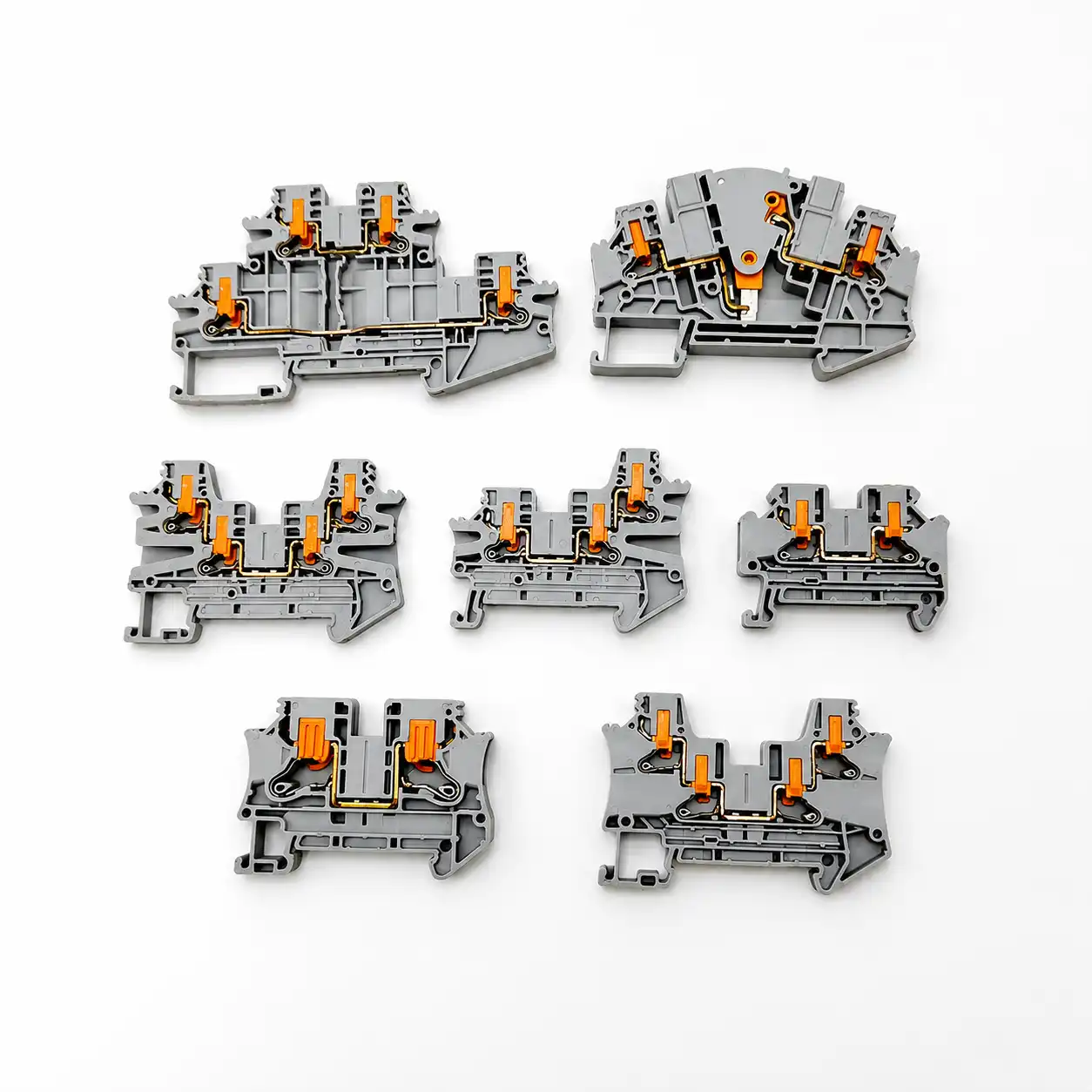
Treat EPMS, BMS and metering as operational interfaces
Electrical power monitoring systems (EPMS), building management systems (BMS), breaker auxiliary contacts, UPS/PDU alarms, energy meters, CTs and remote-control points can determine how quickly a facility identifies and responds to a critical-power event. Terminal blocks can organize these interfaces, but they do not provide measurement accuracy, isolation, protective coordination or safety function by themselves.
Record the signal’s source, reference, normal/fail state, owner, path A/B relevance, fuse/protection or isolation where the equipment requires it, cable/shield treatment and point mapping. A shared alarm common or communications reference can be operationally important even when it carries little power.
- CT and sensor type first: conventional current-output CTs and voltage-output sensors can require different service rules.
- No improvised service sequence: use the exact OEM test, disconnect and recommissioning method.
- Signal identity matters: breaker position, source available, UPS bypass, alarm and shutdown states must not be combined casually.
- EMC is a system property: shielding, functional earth, protective earth, isolation and routing follow the interface and project design.
For broader architecture, review SENTOP’s electrical panel monitoring solution and digital panel meter range.
Turn the terminal layout into a controlled critical-power package
Serviceability means an authorized person can identify, understand and restore the released configuration through the facility process—not simply that spare terminals are present.
| Deliverable | Purpose | Minimum useful content | Release failure to avoid |
|---|---|---|---|
| One-line and equipment schedule | Establish topology, source/load relationships and equipment identity. | A/B or approved common service, UPS/transfer path, PDU/RPP/busway/rack equipment tags, voltage/system notes and revision. | A terminal row that cannot be traced to a source and equipment. |
| Terminal plan | Define every interface location and function. | Equipment, rail, position, circuit function, source/destination, terminal IDs, path identity and functional boundaries. | Generic numbering without location, path or function context. |
| Engineering and procurement BOM | Connect design configuration to purchased and issued material. | Exact manufacturer/MPN, quantity, parent-child accessories, UOM/pack multiple, approved-source/alternate status and revision. | A family name, photograph or generic “terminal hardware” line. |
| Accessory and bridge matrix | Control configuration-dependent items and common points. | Exact ends, covers, partitions, bridges, markers, plugs, rails, fuse/inserts and service items by position/build group. | Implied accessories, undocumented bridges or cross-family substitutions. |
| Marker schedule | Keep permanent field identity synchronized with the design. | Text/file ID, rail/position target, material/carrier where specified, output revision and replacement rule. | Color-only, handwritten or stale labels. |
| Inspection and as-built record | Close the gap between released and accepted equipment. | Identity/count/label checks, configured accessories, approved variances, final revision, commissioning evidence and ownership. | Untracked redlines, verbal handoff or temporary changes left in service. |
Build quantities and pack quantities are different. The released BOM should reconcile calculated use, purchase UOM, issued-to-kit quantity, labeled reserve and final as-built consumption. Use the released line-up to calculate DIN-rail space and document every current-carrying link with the guide to power-distribution jumpers.
A small terminal change can have a system-level consequence
Critical-power changes should pass high-level design, procurement/receipt, pre-install peer-check, commissioning and maintenance-closure gates. The gate asks whether the released documents, exact parts, path identity, protection/thermal evidence, labels and as-built state still agree. It is not a universal physical installation or test sequence.
Opening equipment, disturbing conductors, applying instruments, changing PE/neutral/reference provisions, servicing CT circuits or energizing a modified assembly belongs to authorized personnel qualified for the exact equipment and hazards. Multiple sources, stored energy and backfeed must be controlled through the site procedure.
- Stop on ambiguity: quarantine mixed, damaged, substituted or unidentifiable parts.
- Stop on an undocumented common point: an A/B bridge, shared neutral/reference or alarm common needs an approved design decision.
- Stop on missing evidence: no generic terminal test replaces the OEM/facility commissioning plan.
- Close every change: drawings, BOM, markers, inspection, protection/coordination review and as-built record move together.

Use five hold points from topology to maintained asset
Each hold point has an evidence package and a stop rule. No downstream inspection should conceal an upstream design gap.
Classify the interface
Locate it in the one-line and terminal plan. Name its function, A/B or common-service status, circuit criticality, source/destination and equipment owner.
Release the selection basis
Approve exact MPNs, conductors, ratings, thermal/fault conditions, dependent accessories, conformity evidence and final-assembly use.
Receive and kit exact parts
Reconcile part/pack identity, quantity, lifecycle/alternate status, rail allocation, markers and accessory relationships. Quarantine uncertainty.
Peer-check and commission
Verify path identity, no unreviewed bridges/common points, configured accessories, protection evidence and the approved OEM/facility test plan.
Close and maintain the change
Update labels, drawings, BOM, inspection, variance and as-built records so a future authorized worker can reconstruct the accepted state.
Responsibility boundary: terminal-block standards address component requirements. The applicable switchgear, panel, PDU/RPP, busway, installation and workplace-safety routes remain separate and jurisdiction-specific.
Match component evidence to the finished-equipment route
A standard reference, certification mark or manufacturer data sheet is useful only within its stated scope. None approves a different model or the complete data-center assembly by association.
Terminal function and conductor scope
IEC 60947-7-1:2025 covers support-mounted terminal blocks for copper conductors. IEC 60947-7-2 separately addresses PE/PEN blocks. Aluminum applications need their own declared evidence.
Use the applicable Part with Part 1
IEC 61439-1 provides general rules and is not used alone. The relevant product Part—such as Part 2 for power switchgear/controlgear assemblies or Part 6 for busbar trunking—applies with it.
Use exact category and conditions
UL 1059 covers terminal blocks within its scope. UL Recognized Components are evaluated for use inside a larger end product and retain Conditions of Acceptability.
Keep contexts separated
UL 508A methods belong to eligible industrial-control-panel applications. Do not transfer a default or conditional SCCR to every PDU, RPP, switchboard or non-North-American project.
Verify adopted rules
For U.S. projects, use the NEC edition adopted by the jurisdiction. A publication year on a source list does not prove local adoption or the exact equipment classification.
Qualification and safe work remain site duties
NFPA 70E or other local workplace rules, employer procedures, OEM instructions and facility controls govern exposure, energized work, isolation, verification and authorization.
Component properties are not assembly approval
A flammability class, CTI, temperature index or halogen-free declaration describes a stated material/test condition. It does not establish fire, smoke, tracking or finished-equipment acceptance.
Stored-energy architectures are not interchangeable
An integrated UPS battery and a stand-alone bidirectional ESS can follow different conversion, isolation, fire, certification and commissioning routes. Terminal blocks do not replace battery or ESS disconnect/protection systems.
Keep the released topology reconstructable
Terminal plan, bridge matrix, labels, BOM, peer review, commissioning and as-built records must move together. A small unreviewed field change can compromise A/B identity without changing a component rating.
Uptime Institute Tier objectives and facility redundancy concepts do not certify a terminal block, prescribe a universal A/B color scheme or replace product, assembly, installation and commissioning evidence. Describe only the topology and controls actually approved for the project.
Send the terminal plan, not only a current and quantity
SENTOP can review a drawing, existing model, photograph, sample or BOM and compare terminal families, accessories, labels and packing against the stated interface. Final system design, protection, approval and installation remain with the responsible project team.
Continue with the next engineering check
Use the narrow guide that owns the next question instead of repeating a general rule inside every project.
Data-center terminal-block selection FAQs
These answers provide selection boundaries. They do not replace the exact OEM, facility, fault-study, assembly or jurisdictional requirements.
Are terminal blocks suitable for data center power distribution?
They can be suitable as approved interfaces inside critical-power equipment, including selected power interfaces expressly permitted by the exact equipment and assembly design, plus auxiliary power, metering, alarm, control, PE, neutral/return and monitoring functions. They are not automatically suitable for every feeder or distribution point. Verify the exact component and configured assembly against conductor, load, thermal, fault, protection, approval and jurisdictional conditions.
Can terminal blocks replace a PDU, RPP, busway or rack PDU?
No. Those products perform system-level distribution, transformation, branch protection, tap-off, monitoring or rack-delivery functions. A terminal block may be an internal interface, but it does not replace the tested and engineered distribution product.
How do you keep A and B power paths separate at a terminal strip?
Use an end-to-end identity system: one-line path designation, defined terminal-plan zones or boundaries, explicit bridge/common-point rules, permanent labels, separate BOM allocation, peer review and synchronized as-built change control. Color can help recognition but cannot prove independence.
How is terminal-block current rating selected for a critical-power circuit?
Start with the actual current through the exact connection path. Then verify the configured terminal, conductor, bridges or mating parts, local component ambient, enclosure and adjacent-loading conditions, applicable product/approval data and every other continuous-current ceiling. Verify fault duty and the completed assembly separately.
Does a UL Recognized terminal block make a PDU or panel compliant?
No. UL Recognized Components are intended for use inside a larger certified end product and retain Conditions of Acceptability. The complete PDU, RPP, panel, switchgear or other equipment still follows its applicable product, installation and project evaluation.
Are power distribution blocks and terminal blocks the same thing?
Not necessarily. A PDB is designed and evaluated for a defined distribution function. An ordinary terminal block may not share its incoming/outgoing conductor rules, field-connection status, spacing or fault-rating basis. Select the product category the application requires.
Do neutral terminals need special attention in data centers?
Yes. Neutral/return current depends on the source and conductor system, phase loading, nonlinear loads and harmonics, bonding/grounding design and equipment topology. Do not assume a reduced, shared or bonded neutral arrangement from a generic data-center rule.
Can an AC-rated terminal block be used in a DC data-center architecture?
Only when the exact terminal and complete equipment documentation cover the intended DC application. DC can have different fault-current, interruption, isolation, earthing, protection and arc behavior. A similar printed voltage number is not a substitute for DC evidence.
What accessories must appear in a data-center terminal-block BOM?
List every item needed for the released configuration: rail hardware, end clamps, end plates or covers, partitions, bridges, markers and carriers, plugs, fuse/component inserts where specified, and approved service/test items. Link each item to its compatible terminal family and position or build group.
Who may modify terminal assemblies in critical-power equipment?
Only personnel authorized by the facility and qualified for the exact equipment, sources and hazards, working under the OEM instructions, approved drawings, facility change process, electrical-safety program and commissioning or maintenance procedure. A product data sheet or terminal label does not grant operating authority.
Standards and manufacturer sources used for the boundaries above
Verify the current edition, exact product, certification status, local adoption and project applicability before release.
- IEC 60947-7-1:2025. Support-mounted terminal blocks for copper conductors. IEC publication record.
- IEC 60947-7-2. Separate scope for protective-conductor terminal blocks. IEC publication record.
- IEC TS 60947-7-5. Terminal blocks for aluminum and aluminum-copper conductor applications. IEC publication record.
- IEC 61439-1 and IEC 61439-2. General rules and power switchgear/controlgear assembly context. Part 1 and Part 2.
- IEC 61439-6. Busbar trunking system context. IEC publication record.
- ANSI/UL 1059. Terminal-block component scope and end-product suitability boundary. UL Standards record.
- UL Component Recognition. Conditions of Acceptability and component-versus-end-product distinction. UL guidance.
- UL industrial-control-panel misapplications. Terminal block versus PDB application warning. UL guidance.
- UL SCCR guidance. Available fault current, component and assembly context. UL guidance.
- ABB data-center power distribution. System-level equipment and architecture context. ABB data-center page.
- WAGO data-center application. Example of terminal blocks between CTs and energy meters. WAGO data-center solutions.
- Uptime Institute. Dual-corded power, A/B labeling, documentation and quality-control context. Uptime Institute journal.
- OSHA 29 CFR 1910.333. De-energized work, qualified-person and verification context for U.S. workplaces. OSHA regulation.
- NFPA 70, 70B and 70E. U.S. installation, maintenance and workplace electrical-safety context; verify the adopted/current project edition. NFPA 70, NFPA 70B and NFPA 70E.
- ASHRAE TC 9.9 / data-center planning. Datacom-equipment environmental context, not a terminal-block derating curve. ASHRAE site-planning guidance.
- UPS battery and ESS context. System-level storage certification and installation requirements remain separate from a terminal interface. UL ESS testing and certification and NFPA 855.
- UL 94 limitations. Small-scale polymer flammability results do not replace finished-product or facility fire assessment. UL Code Authorities guidance.
Keep the approved terminal system connected to the critical-power record
Send the application, one-line excerpt, terminal plan, existing model or sample, electrical/conductor conditions, accessory matrix, A/B labeling, quantity, destination and documentation needs. SENTOP can review product matching and supply details without replacing the project’s system engineering or approval authority.



