

What Is a 3-Pole Circuit Breaker, and How Does It Work?
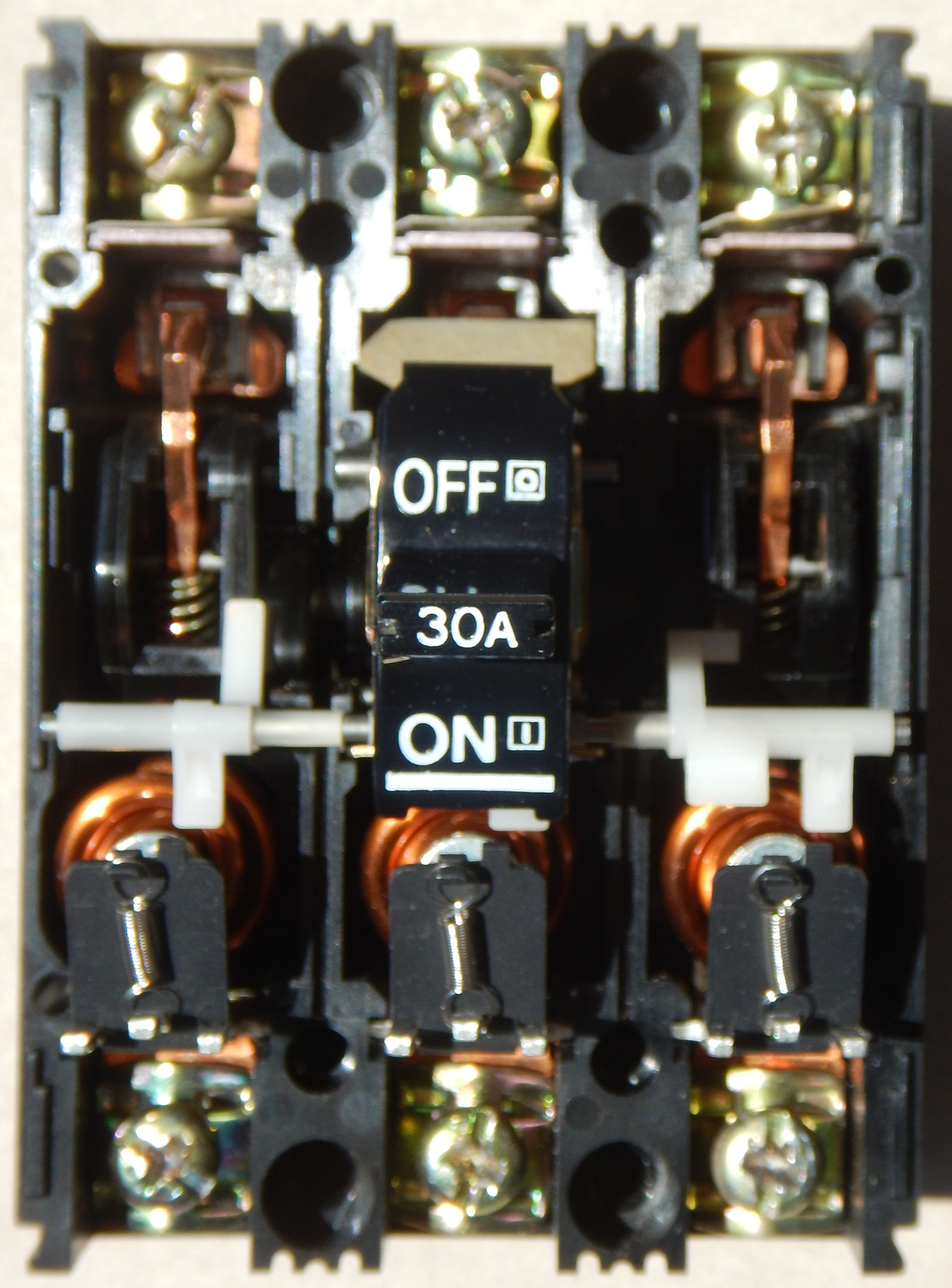
A three-pole circuit breaker has three main current paths and is normally used on the three ungrounded conductors of a three-phase circuit. If the exact product has an internal common-trip mechanism, a qualifying trip on one linked pole opens all associated poles. The label 3P describes pole count; it is not a complete voltage, fault-duty, neutral, or compatibility specification.
Three poles describe three switched current paths—not the whole application
In the usual AC application, the three poles carry L1, L2, and L3 of one three-phase circuit. The breaker can switch those paths and open them when its selected protective release operates. Pole count alone does not say how many poles have overcurrent sensing, whether the device is common trip, or whether it is suitable for isolation.
It also does not define voltage, current, interrupting capacity, trip curve, ground-fault function, neutral treatment, DC use, panel approval, or coordination. Those conditions come from the exact catalog number, markings, certificate or listing, instructions, and completed system design.
Use “3P” to start the conversation, then specify the circuit. Provide the one-line diagram, voltage and grounding, load current by phase, available fault current, neutral requirement, panel data, environment, and target market.
How a three-pole circuit breaker carries and interrupts current
The construction differs across miniature, molded-case, and power circuit breakers. These five elements explain the common functional path without turning the article into a repair guide.
Insulated structure and terminals
The frame supports the poles, terminals, operating parts, and insulation system for the product's rated conditions.
Terminals, conductor material, spacing, and mounting remain model-specific.Three main current paths
Each pole has a contact path. When closed, the pole carries its phase current under the stated rating and conditions.
Do not add the three current ratings into one “total ampere” number.Overcurrent evaluation
Thermal-magnetic or electronic releases can provide long-time, instantaneous, or other documented functions.
Ground-fault, residual-current, arc-fault, motor overload, and phase-loss functions are not implied by 3P.Opening and common trip
A genuine common-trip design links the protective opening of its associated poles through an internal mechanism.
Externally tied handles can link manual operation without creating the same trip behavior.Interrupting current
When contacts separate, the breaker controls and extinguishes the arc within its marked interruption capability.
Interrupting ratings apply only at the stated voltage and system conditions.Common trip is not phase-loss detection. The breaker opens its linked poles when its mechanism trips. A lost upstream phase, open fuse, failed contactor, or broken conductor may require separate phase monitoring or motor protection. Read more about real event patterns in SENTOP's circuit-breaker tripping guide.
Thermal-magnetic and electronic trip units do not offer the same functions
A thermal-magnetic breaker typically uses a thermal element for time-delayed overload response and a magnetic element for rapid high-current response. An electronic trip unit uses sensors and electronics to perform its documented protection logic. Neither approach can be judged from pole count alone.
- Thermal response: trip time depends on current magnitude, product curve, ambient conditions, and construction.
- Magnetic or instantaneous response: pickup and timing are exact-model data, not a universal “D curve for motors” rule.
- Electronic functions: long-time, short-time, instantaneous, equipment ground-fault, metering, alarms, and communications may be options.
- LSI/LSIG shorthand: only use it when the exact trip unit documents those functions and settings.
- Motor circuits: a 3P breaker can be one part of protection, but motor overload, phase loss, control, and starting must be resolved in the complete design.
3P, handle-tied poles, 3P+N and 4P are not interchangeable
The terms describe different constructions and may change across product families. Use the manufacturer's definition and the approved one-line diagram, not a label shortcut.
| Configuration | What the label usually describes | Neutral boundary | What must be verified |
|---|---|---|---|
| 3P COMMON TRIP Three-pole breaker | Three associated phase paths in one assembly. A true common-trip mechanism opens its linked poles when one qualifying trip occurs. | The neutral is normally outside those three main poles. | Common trip, protected-pole notation, voltage/system application, fault rating, and isolation suitability. |
| NOT EQUIVALENT BY DEFAULT Three handle-tied 1P devices | An identified handle tie may link manual operation in an application that specifically permits it. It does not automatically create internal common trip. | Depends on the exact circuit and evaluated arrangement. | Applicable product marking, panel approval, simultaneous-disconnect requirement, and whether common trip is required. |
| PRODUCT-SPECIFIC TERM 3P+N | Often three protected phase poles plus a neutral pole that switches with them. Some families use the term differently or use a 3P frame with external neutral sensing. | The neutral may switch without an independent overcurrent release. | Exact catalog definition, neutral contact sequence, sensing/protection, and complete system suitability. |
| FOUR POLES 4P with three protected | Four poles open; three phase poles provide the documented overcurrent function. Some families call this 4P3D or 4P3d. | The neutral can be switched but full neutral overcurrent protection is not automatic. | Protected-pole designation and any 0%, 50%, or 100% neutral protection marking. |
| FOUR PROTECTED 4P with four protected | Four poles open, with the fourth pole having the documented protection under stated conditions. Some families call this 4P4D or 4P4d. | The neutral is switched and protected within the exact product design. | Neutral current profile, trip-unit capability, pole sequence, voltage system, and local requirements. |
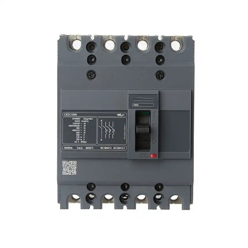
A fourth pole does not tell you how the neutral is protected
This SENTOP four-pole MCCB shows why pole count must be read with the exact trip-unit and neutral data. A visible neutral pole may be switched without full overcurrent sensing, may use partial neutral protection, or may be protected under model-specific conditions.
Illustrative SENTOP product-family image. Confirm the exact catalog number, markings, neutral function, certification, and approved application before specification.For a broader application map, use the verified guide to SP, TP, TPN, and 4P breaker use. For a direct comparison, see 3-pole vs 4-pole circuit breakers.
What “three-pole” does not prove
These errors often appear in purchase requests and replacement work. Each one hides a system condition that must be documented.
100 A × 3 = 300 A
The marked ampere rating is read for each applicable pole under the stated conditions. It is a 100 A device on each applicable phase path, not a 300 A device.
Check the current on every phase, load duty, balance, ambient conditions, and exact trip data.All three-pole devices are common trip
Common trip is an internal function that must be confirmed. Linked handles can provide simultaneous manual action without the same protective linkage.
Use the exact model marking and instruction, not handle appearance.3P automatically handles neutral
A conventional 3P breaker normally addresses the three phase paths. Neutral switching, sensing, and overcurrent protection are separate decisions.
Resolve 3P, 3P+N, 4P3D, or 4P4D from the actual architecture.3P includes every protection function
Pole count does not imply residual-current/GFCI, equipment ground-fault, AFCI, phase sequence, phase loss, or motor-overload protection.
List every required protective function in the specification.A kA value works at every voltage
Never multiply an interrupting rating by three. Read the marked rating at its stated voltage and system condition.
Non-solidly-grounded-wye systems can also require an individual-pole interruption review.Same amps and physical fit mean compatible
Panel label, accepted breaker family, bus interface, voltage, fault duty, trip type, accessories, and assembly short-circuit rating all matter.
A device that snaps into place can still be an unapproved substitution.Any 3P breaker can be used for DC
DC requires an explicit rating. Higher DC voltages can require a manufacturer-defined arrangement of multiple poles in series.
Never transfer an AC rating to DC because the breaker has spare poles.Any two poles can serve a single-phase load
Not by default. A three-pole product needs an explicit single-phase marking or manufacturer instruction, including the allowed pole pair and system conditions.
Use the separate guide to 3-pole breakers in single-phase panels.Open equals electrically safe
A breaker is suitable for isolation only when marked and applied for that function. Sources, line terminals, controls, or backfeed may remain energized.
Use the complete energy-control and verification procedure.A 3P MCB, MCCB, power breaker, and supplementary protector do different jobs
Avoid rigid current ranges in a global guide. Start with the role and evaluated product category, then compare the exact ratings and functions.
Final and smaller branch circuits
Often fixed or limited trip characteristics in compact distribution assemblies. Product scope can follow household/similar or industrial standards, depending on model and market.
Verify curve, poles, fault rating, voltage, assembly compatibility, and standard.Feeders and larger branch duties
Molded-case breakers can offer thermal-magnetic or electronic trips, several frames, accessories, and coordination options.
Match the frame and trip unit to the complete feeder, fault, panel, and accessory requirement.Main distribution and critical power
Low-voltage power or air circuit breakers can add short-time capability, advanced protection, metering, communications, maintainability, and drawout forms.
Protection and assembly studies determine the required configuration.Protection inside equipment
A breaker-like supplementary protector has a narrower evaluated purpose. It does not automatically replace required branch, feeder, or service overcurrent protection.
Confirm its certification category and place in the complete equipment.Compare the commercial categories through SENTOP's MCB vs MCCB guide, then review the miniature circuit-breaker range or molded-case circuit-breaker range. Exact certifications and ratings remain model-specific.
Read the ratings as one connected set
A catalog number can combine frame, trip, poles, voltage, fault rating, mounting, terminals, accessories, and certification. Connect every number to its test or application condition.
| Specification | What it answers | What the buyer must supply or verify | Common error |
|---|---|---|---|
| Pole and protected-pole notation | Which main paths switch, which are protected, and whether the product is common trip. | 3P, 3P+N, 4P3D/3d, 4P4D/4d, neutral behavior, and product-family terminology. | Assuming each visible pole has the same release or neutral protection. |
| Voltage and voltage to ground | The AC/DC voltage envelope and permitted system arrangement. | Line-to-line, line-to-neutral, frequency, grounding/earthing, source, and any slash-rating conditions. | Using 480Y/277 V on a system that exceeds the allowed voltage to ground. |
| Rated current and trip rating | The current capability and protection assigned to each applicable current path. | Current by phase, continuous duty, inrush, imbalance, ambient/enclosure, conductor/circuit, and trip behavior. | Adding pole ratings or selecting from load nameplate current alone. |
| Interrupting rating, Icu, Ics, kAIC | The fault-interruption capability under the applicable standard, voltage, and system conditions. | Available fault current at the point, applied voltage, grounding, individual-pole duty where relevant, and standard context. | Mixing IEC Icu/Ics with UL interrupting ratings or treating one kA value as universal. |
| Trip unit and functions | Thermal-magnetic, electronic, instantaneous-only, equipment ground-fault, metering, alarms, or communication capability. | Exact trip-unit catalog number, required functions, approved settings study, sensors, power supplies, and accessories. | Assuming every electronic breaker has LSIG or motor protection. |
| Assembly short-circuit rating | The short-circuit suitability of the panelboard, switchboard, or equipment combination. | Assembly marking, accepted breaker, series combination if applicable, bus, enclosure, and available fault current. | Assuming a higher-kA breaker raises the completed assembly rating. |
| Frame, terminals, and mounting | How the breaker integrates mechanically and thermally. | Panel model, bus interface, fixed/drawout form, conductor material/count, lugs, orientation, clearance, and accessories. | Using physical fit as evidence of electrical or listed compatibility. |
| Standard, listing, and certificate | The evaluated product category and market scope. | Destination country, adopted rules, client specification, exact model/certificate, factory, edition, and conditions. | Calling an IEC standard, CE mark, UL recognition/listing, and local approval the same thing. |
IEC 60947-2:2024 covers industrial low-voltage circuit breakers within its published scope. IEC 60898-1 covers a different household/similar-installation product context. North American molded-case circuit breakers are commonly evaluated to UL 489. The standard's scope is not the product's rating; use the exact active certification record and datasheet.
Where three-pole circuit breakers are used—and what 3P still cannot decide
The application identifies the questions; it does not select the model. These examples show the next engineering boundary.
One three-phase circuit
The three phase conductors can be protected and opened as one circuit.
Resolve starting, overload, phase loss, control, disconnecting, and coordination in the complete motor design.Three-phase equipment duty
A 3P breaker can protect the supply path for a documented load.
Use equipment data, duty cycle, inrush, ambient conditions, conductor design, and local rules.Panel or downstream load group
The breaker can feed a defined three-phase distribution section.
Confirm neutral policy, panel SCCR, fault current, selectivity, and accepted breaker family.Protective boundary for a feed
The device can carry and interrupt the specified input circuit.
Transformer inrush, source fault contribution, grounding, downstream protection, and curve data remain essential.Critical-power auxiliary feed
Three-phase distribution is common around power-conversion and standby systems.
Transfer behavior, separately derived source rules, neutral/grounding, backfeed, and control supplies need engineered review.Replacement or spare request
A breaker with the same nominal current may appear available.
Verify panel marking, family, frame, trip, bus/terminal interface, accessories, fault rating, and approved replacement path.For the system-level context, see SENTOP's guide to three-phase distribution-box functions. Panel builders can also use the broader low-voltage protection selection guide.
Eight checks before approving a three-pole breaker
Use this workflow for a new design, supplier comparison, replacement review, or project RFQ. It is not an installation procedure.
Define the circuit role
Main, feeder, branch, motor-related feeder, transformer input, UPS/PDU feed, or internal equipment protection.
Start with the one-line diagram.State the source
AC or DC, voltage, voltage to ground, frequency, phase/wire count, grounding, and generator/UPS/PV/battery sources.
“Three phase” is not enough.Quantify the load
Current by phase, operating pattern, continuous duty, inrush, motor starting, imbalance, harmonic or neutral-current concerns.
Use real duty data, not an arbitrary margin.Resolve neutral behavior
Is neutral present? Must it switch? Does it need sensing or overcurrent protection? What pole sequence is required?
Choose the configuration after this decision.Calculate fault duty
Available fault current at the location, applied voltage, grounding, upstream protection, assembly rating, and coordination goal.
Do not compare bare kA numbers.Match the assembly
Panel/switchboard model, accepted family, frame, bus/terminal connection, mounting, fixed/drawout form, space, and enclosure.
Physical fit is only one input.Specify functions
Trip technology, common trip, ground-fault, auxiliaries, shunt trip, undervoltage release, motor operator, metering, and communication.
List required functions explicitly.Verify evidence
Exact standard/listing, certificate status, target market, manufacturer instructions, coordination data, labels, drawings, and traceability.
Approve a catalog number, not a generic description.
Three poles opening together does not establish a safe work condition
A trip or manual OFF position is an operating state, not proof that the equipment is de-energized. The line side, alternate source, generator, UPS, PV, storage, control power, induced voltage, or downstream backfeed can remain hazardous.
- Do not open a live panel to read labels, tighten terminals, move conductors, change settings, or test compatibility.
- Identify every energy source and stored-energy path before exposed work.
- Use the approved LOTO procedure and have a qualified person verify absence of voltage with suitable test equipment.
- Do not repeatedly reset an unexplained trip or increase the breaker rating to stop operation.
- Escalate heat, odor, smoke, arcing, water, damage, shock, or repeated trips and keep affected equipment out of service.
- Re-energize only after the cause, repair, settings, guards, documentation, and required tests are complete.
Send SENTOP the circuit duty—not only “100 A, 3P”
SENTOP can review a three-pole breaker family, replacement reference, model, photo, drawing, sample, or BOM against a documented low-voltage project. System design, protection studies, installation, approval, commissioning, and field fault diagnosis remain with qualified local professionals.
Continue with the guide that matches your next decision
Three-pole circuit breakers
Short answers for definition and selection. Exact product markings and the completed system remain controlling.
What is a three-pole circuit breaker?
A three-pole circuit breaker has three main current paths in one assembly. It is normally used on the three ungrounded conductors of a three-phase circuit. If the exact device is common trip, a qualifying trip on one linked pole opens all associated poles. Voltage, trip functions, fault rating, and neutral behavior still require separate verification.
Does a three-pole breaker always mean three-phase power?
It is normally intended for three-phase use, but pole count alone does not approve every application. A stated single-phase use is acceptable only when the exact breaker marking and manufacturer instructions permit that use, identify the pole arrangement, and match the voltage system and panel.
Does a 100 A three-pole breaker provide 300 A?
No. The 100 A rating is not added across the poles. Each applicable phase path carries current under the breaker's stated conditions. Review current by phase, continuous duty, imbalance, ambient and enclosure conditions, conductors, terminals, and trip characteristics.
Why do all three poles open when only one pole trips?
That is the purpose of a genuine internal common-trip mechanism: a qualifying trip on one linked pole releases the mechanism and opens all associated poles. An external handle tie can link manual operation without automatically providing the same protective trip behavior.
What is the difference between 3P, 3P+N, and 4P?
3P identifies three main poles, normally the phase paths. 3P+N often means three protected phases plus a simultaneously switched neutral, but the term varies by product family. 4P identifies four poles, yet the neutral may have no, partial, or full overcurrent protection. Read the protected-pole notation and exact manufacturer definition.
Does a three-pole breaker disconnect the neutral?
Normally no; the conventional 3P arrangement addresses the three phase paths. Neutral switching, sensing, and overcurrent protection are separate choices. If the system requires a switched neutral, use the approved configuration and pole sequence defined by the design and product instructions.
Does every three-pole breaker provide ground-fault protection?
No. A 3P label describes pole count. Equipment ground-fault, residual-current/GFCI, arc-fault, phase-loss, motor-overload, and other protective functions require exact documented devices or trip-unit features. Specify each needed function separately.
Can a three-pole breaker protect a motor circuit by itself?
It can be part of a motor branch-circuit protection and control system, but pole count alone does not provide every motor function. Starting, short-circuit, overload, phase-loss, disconnecting, control, and coordination requirements depend on the motor, equipment, breaker, overload device, and local rules.
Can I replace a three-pole breaker with any model of the same amperage?
No. A valid replacement must also match the panel or switchboard's accepted family, voltage and fault duty, pole/common-trip configuration, frame and trip unit, bus or terminal interface, accessories, certification, and any series or coordination conditions. Physical fit is not approval.
Can a three-pole breaker be used on DC?
Not unless the exact product has an explicit DC rating for the actual voltage and system. Some DC applications require a manufacturer-specified series connection of poles. Never apply an AC-only breaker to DC or invent a pole arrangement from a generic diagram.
Primary technical references
- IEC 60947-2:2024 — industrial low-voltage circuit-breaker scope and current standard context.
- IEC 60898-1:2015+A1:2019 — household and similar-installation AC circuit-breaker scope.
- UL 489, Edition 14 — current North American molded-case circuit-breaker, switch, and enclosure standard record.
- UL Solutions Molded-Case Circuit Breaker Marking and Application Guide — voltage, system, poles, neutral, DC, common application, and marking boundaries.
- UL Solutions Panelboard Application Guide — assembly rating, accepted field units, and compatibility boundaries.
- Schneider Electric common-trip explanation — internal common trip versus an external handle tie.
- Schneider Electric per-pole current explanation — multi-pole ampere ratings are not added.
- Eaton Circuit Breaker Fundamentals — frame, operating mechanism, contacts, arc control, and trip-unit concepts.
- Eaton individual-pole interrupting capability guidance — system grounding and single-pole fault-duty boundary.
- OSHA 1910.333 — workplace de-energization, energy control, verification, and qualified-person boundaries.
Turn “3P breaker” into a complete, reviewable specification
Send the one-line diagram, source and grounding, voltage, current by phase, load and inrush, available fault current, pole/neutral requirement, panel or switchboard data, required trip functions, environment, target market, documents, quantity, and delivery needs.
