
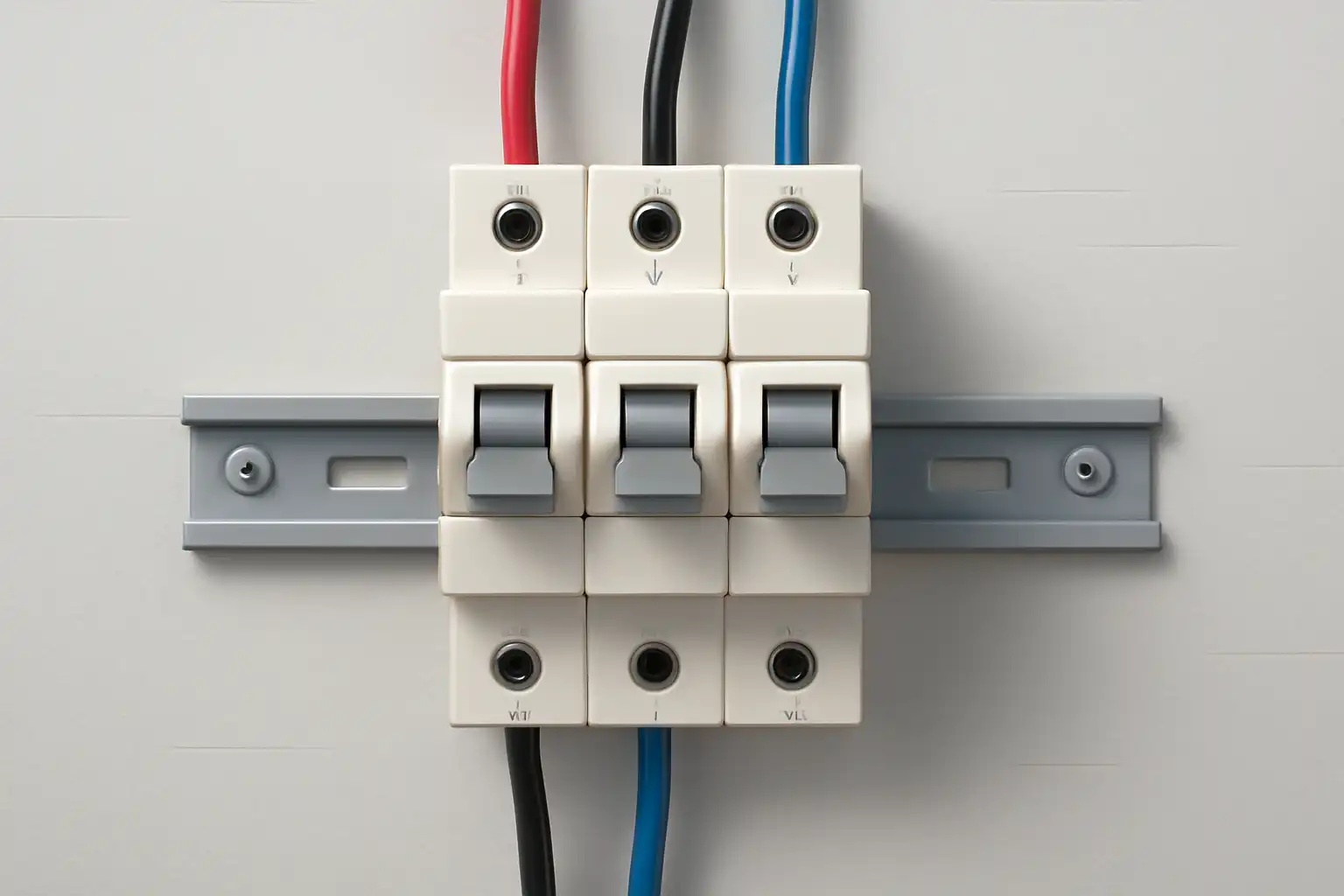
Can You Use a 3-Pole Breaker in a Single-Phase Panel?
Usually, no. A three-pole breaker cannot create three-phase power, and physical fit is not approval. A narrow use may be valid only when the exact breaker is marked for single-phase operation and the exact panelboard, mounting arrangement, voltage system, pole use, and manufacturer instructions approve the complete combination.
Use a listed two-pole breaker by default; treat a three-pole option as a documented exception
For an ordinary single-phase line-to-line circuit, the expected solution is usually a two-pole common-trip breaker that the panel manufacturer identifies for that panel. A three-pole device adds another protected current path, but it does not add another supply phase.
The breaker’s single-phase marking, the approved pole arrangement, the panelboard label or compatibility document, the electrical ratings, and the completed assembly instructions must all support the use. “It clips onto the bus” is not one of those approvals.
A manufacturer may permit a named three-pole breaker to serve a single-phase circuit using a specified pair of poles. Another model may require a named main-breaker kit. A visually similar device may prohibit the same arrangement. Product-family instructions cannot be transferred to another catalog number.
A valid answer needs four locks to close
A “yes” on one item cannot override a “no” or an unknown on another. Keep the source, device, assembly, and protection evidence together.
Identify the real system
Record single-phase voltage, number of conductors, grounded-conductor arrangement, frequency, source type, and voltage to ground.
Do not assume every single-phase panel is a North American 120/240 V split-phase panel.Read the exact catalog number
Check pole count, common-trip construction, AC or DC rating, straight or slash voltage, current, interrupting rating, terminals, and single-phase marking.
“Three pole” describes the device; it does not approve how two poles may be used.Prove the combination
Use the panel label, OEM breaker table, named mounting kit, or an applicable Classified replacement record for the exact catalog numbers.
Same brand, same width, or a tight mechanical fit is not panelboard approval.Verify the finished assembly
Check deadfront fit, bus engagement, conductor terminals, fault current, assembly rating, protection coordination, neutral and grounding design, and local rules.
A higher breaker kA value does not raise the panel’s documented short-circuit rating.Poles, phases, panel spaces, and common trip are different things
Many wrong answers begin by treating these terms as synonyms. They describe different parts of the electrical system. For a broader product map, see SENTOP’s guide to SP, TP, TPN, and 4P circuit breakers.
The source waveform arrangement
Single-phase and three-phase describe the power source. A breaker cannot change one into the other.
One switched current path
A three-pole breaker has three paths operated by one mechanism. Whether all three are protected depends on the exact design.
A physical mounting position
A space can align with a bus connection. The pattern depends on the panel’s internal construction and approved devices.
Internal simultaneous tripping
When one associated pole trips, the common mechanism opens all required poles. A handle tie alone does not create this internal action.
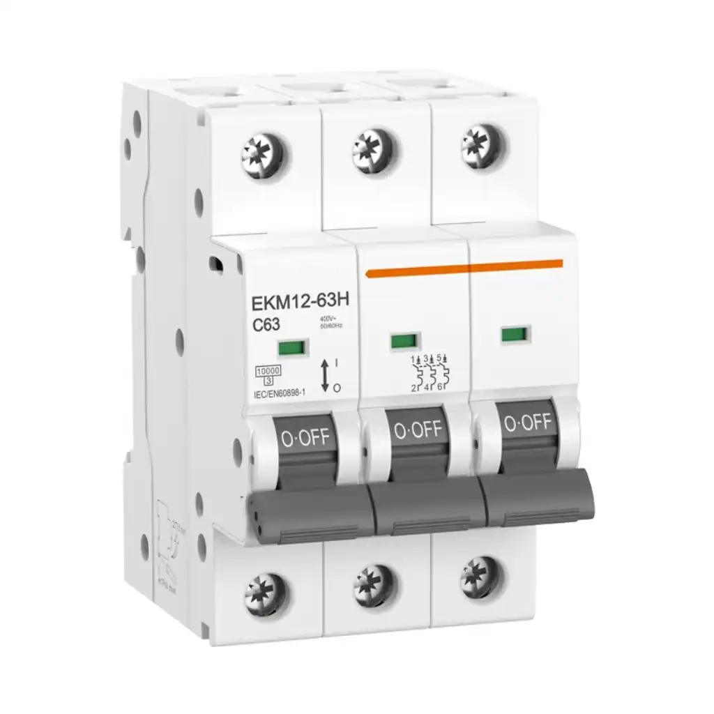

Why three adjacent positions may be L1–L2–L1, not three phases
A common 120/240 V residential or light-commercial service has L1, L2, and a center-tapped neutral. Each line is normally 120 V to neutral and 240 V line to line. The panel bus often alternates the two available legs down the board.
| Position example | Bus leg | What it can tell you | What it cannot tell you |
|---|---|---|---|
| Space 1 | L1 | The first branch position may connect to one line leg. | It does not prove the pattern of another panel model. |
| Space 2 | L2 | An adjacent approved two-pole device may span both legs. | It does not authorize an unlisted breaker family. |
| Space 3 | L1 again | Three consecutive spaces can repeat the first leg. | The outside spaces do not automatically form a 240 V pair. |
| Other panel design | Read the label | Some single-phase panels use different bus, connector, or main-breaker structures. | Do not transfer an L1–L2 pattern or “outside poles” rule without evidence. |
Critical distinction: when a manufacturer instruction says “use the outside poles,” it can refer to the outer current paths inside a named three-pole breaker or a named main-breaker kit. It does not mean “use the outside two of three consecutive branch spaces.” Follow the drawing for the exact device and assembly.

The panel label is the first evidence—not the last box to check
A panelboard is evaluated as an assembly. Breaker geometry, clips, bus contact, rejection features, deadfront openings, heat, conductor terminals, and short-circuit behavior all matter. A breaker can appear to fit while using the wrong contact design or leaving the assembly outside its documented scope.
- Match the panel catalog and series. Read the complete nameplate, not just the brand on the door.
- Match the permitted breaker type. The exact type designation or a valid replacement classification must cover the exact panel.
- Match the mounting method. Plug-on, bolt-on, main-breaker kits, lugs, fillers, and deadfront parts are assembly-specific.
- Match the electrical system. Voltage, frequency, phase, current, line-to-ground conditions, and AC/DC use must be within ratings.
- Match fault duty. Compare available fault current with the breaker interrupting rating and the panel’s approved short-circuit arrangement.
- Keep the approval record. Store the label photo, instruction revision, breaker data, and compatibility evidence with the panel schedule.
For an existing unknown assembly, start with breaker identification. If the panel itself needs replacement, the project must address the complete service or distribution scope—not only the breaker. See the panel replacement planning guide.
Do not turn one unused path into an undocumented design
The most dangerous shortcuts treat the third pole as harmless spare hardware. It remains part of the device and its line-side relationship can depend on the construction.
Only if the exact instructions permit it
A single-phase marking may specify any two poles, a particular pair, or a named kit. Without that instruction, an unloaded third terminal does not make the arrangement valid.
Never assume an unused load terminal means every part of that pole is de-energized.Never assume the third pole is neutral
A normal grounded conductor usually goes to the approved neutral assembly, not a standard phase pole. Some devices have a clearly identified neutral pole for a defined application.
Use a switched or protected neutral only when the exact design, markings, and local requirements call for it.Do not add voltage ratings
Some DC breakers use a manufacturer-specified series-pole diagram. That does not allow a buyer to improvise a higher voltage rating on another breaker.
Do not connect breaker poles in series unless the exact documentation states the configuration and resulting rating.Do not add ampere ratings
Current will not divide perfectly between improvised parallel paths. Contact resistance, mechanism behavior, terminals, and heat make simple arithmetic invalid.
Never parallel poles to increase ampacity unless the product is expressly designed, marked, and documented for it.Ampere rating is only one line of the specification
A correct handle number cannot fix the wrong voltage, panel, conductor, fault duty, trip function, or application. Verify the exact catalog data and the assembly conditions.
Why the slash matters
On a slash-rated breaker, both numbers matter. The lower number limits voltage from a conductor to ground. The higher number limits voltage between conductors only on the system identified by the rating. A slash-rated device should not be moved to an ungrounded, corner-grounded, resistance-grounded, or other system merely because its higher number matches the line-to-line voltage.
When the project uses another regional system, do not translate a North American label by appearance. Start from the locally applicable product and assembly standards, certification route, system earthing, and manufacturer documentation.
The best answer depends on what the breaker is meant to do
These scenarios separate a normal product substitution from a documented factory arrangement or a larger system-design problem.
Ordinary single-phase branch circuit
The panel has a normal line-to-line load and an approved two-pole breaker is available. A three-pole device adds cost, space, and questions without a clear function.
Decision: use the listed two-pole breaker specified for the panel.Named three-pole main-breaker kit
The panel manufacturer identifies an exact three-pole frame, connector kit, deadfront arrangement, and two-pole use for a single-phase panel.
Decision: potentially valid only as that complete named assembly.Three-phase motor at a single-phase site
Changing the breaker does not supply a third phase. Motor starting, converter input, output, controls, harmonics, protection, and derating all need engineering review.
Decision: solve the power-conversion problem, not the pole-count problem.Legacy or unknown panel
The label is missing, obsolete, damaged, or does not list the proposed breaker. Mechanical fit cannot recreate the lost compatibility evidence.
Decision: identify the assembly or plan a qualified panel replacement—do not guess.Procurement shortcut: choose by approved combination, not by breaker alone. SENTOP’s single-pole vs double-pole guide explains the usual branch-circuit choices. For larger feeder and adjustable-trip applications, use the exact MCCB documentation and assembly design.
Six checks before a model reaches the purchase order
This process keeps the distributor, panel builder, engineer, and inspector working from the same evidence. It also prevents a correct product from being used in the wrong assembly.
Record the electrical system
Capture nominal voltage, phase, frequency, number of conductors, grounding arrangement, source type, load duty, and available fault current.
Evidence: one-line diagram, site data, and design basis.Identify the panel completely
Photograph the full nameplate. Record manufacturer, catalog, series, bus rating, voltage, short-circuit data, approved breaker types, and enclosure/deadfront details.
Evidence: label image and current panel documentation.Identify the breaker completely
Record catalog number, type, poles, common-trip status, current, voltage, AC/DC use, interrupting rating, terminals, trip curve or unit, and certifications.
Evidence: active datasheet and certification record.Find the single-phase permission
Look for “single phase,” the permitted pole pair, a marked diagram, or a named manufacturer kit. Do not infer permission from a reseller title.
Evidence: exact instruction revision or product marking.Validate the assembly
Confirm bus contact, mounting, deadfront, neutral and grounding design, conductor range, terminals, heat, coordination, and short-circuit conditions.
Evidence: approved combination and completed engineering review.Lock the BOM and records
Put exact part numbers, accessories, instruction versions, required certificates, labels, and inspection points into the bill of materials and project file.
Evidence: controlled BOM, drawing, and handover package.Compatibility research is not authorization to open a panel
A main breaker in the OFF position does not always remove voltage from every exposed part. Line-side conductors, generators, UPS systems, photovoltaic systems, batteries, control power, or load-side backfeed may remain energized.
- Use a qualified person who knows the equipment, hazards, and locally required work practices.
- Identify and disconnect every source; control stored energy; apply the required lockout/tagout procedure.
- Verify absence of voltage at every possible exposure point with suitable test equipment, including possible backfeed.
- Do not treat a selector, trip indication, open handle, interlock, or panel schedule as proof of an electrically safe work condition.
- Do not install, test, torque, or modify a breaker from generic web values. Follow the exact product and assembly instructions.
Send the evidence, not only “3P, 20A”
SENTOP can help panel builders, equipment manufacturers, distributors, and project buyers match a low-voltage breaker or distribution BOM. Provide the system and assembly information so the answer is tied to an exact model and project market.
Field inspection, code decisions, permitting, and installation remain the responsibility of the project designer, authority, panel builder, and locally qualified electrical professionals.
3-pole breaker and single-phase panel FAQ
These answers assume product and panel compatibility still has to be proven. Local requirements and exact manufacturer instructions control the final design.
Can I use only two poles of a three-pole breaker?
Only when the exact breaker is marked for single-phase use and identifies the permitted pole pair, and the exact panel or approved kit accepts that breaker. Without that evidence, use the approved two-pole device.
Should I always use the two outside poles?
No. “Use outside poles” is a model-specific instruction for a named breaker or assembly. It is not a general rule for panel spaces. On a common split-phase branch bus, the outside two of three consecutive positions may connect to the same leg.
Can the unused third pole be left empty?
Possibly, but only when the exact product marking and instructions permit that single-phase arrangement. An unused load terminal does not prove every part of that pole is de-energized or that the breaker-panel combination is approved.
Can I use the third pole to switch the neutral?
Not on a standard three-phase breaker by assumption. A neutral pole must be clearly identified and used within a documented design that satisfies the circuit, product, assembly, and local requirements.
Does a three-pole breaker create three-phase power?
No. It only switches and protects current paths. A three-phase load at a single-phase site needs a suitable engineered source or conversion system, such as a compatible VFD for some motor applications.
Can I parallel two or three poles to increase amperage?
No—not as a field shortcut. Pole ratings cannot simply be added. Parallel or series arrangements are acceptable only when the exact breaker is designed, marked, and documented for that configuration and its resulting ratings.
If the breaker fits the bus, is it compatible?
No. Physical fit is not approval. Verify the panel label, breaker type, exact catalog numbers, mounting and deadfront, electrical ratings, fault-duty conditions, certification record, and manufacturer instructions.
Is a higher interrupting rating always safer?
The breaker interrupting rating must meet or exceed the available fault current under its marked conditions, but a higher value on one breaker does not automatically raise the short-circuit rating of the panel or make an unapproved combination acceptable.
Standards and manufacturer evidence used for this guide
References define product, assembly, and safety boundaries. They do not approve an unnamed breaker-panel combination. Verify the active standard edition, local adoption, exact catalog-number documentation, and certification status for the project.
