
5 Proven Methods for Terminal Block Corrosion Prevention
Preventing terminal corrosion is a systems job: classify the exposure, specify a compatible terminal-and-conductor combination, install it exactly as documented, control ingress and condensation, then inspect according to risk. No universal grease, enclosure number or calendar interval can replace those five controls.
Record water paths, condensation, salt or process chemicals, conductor metal, temperature, vibration and required approvals before choosing the terminal or any protective treatment.
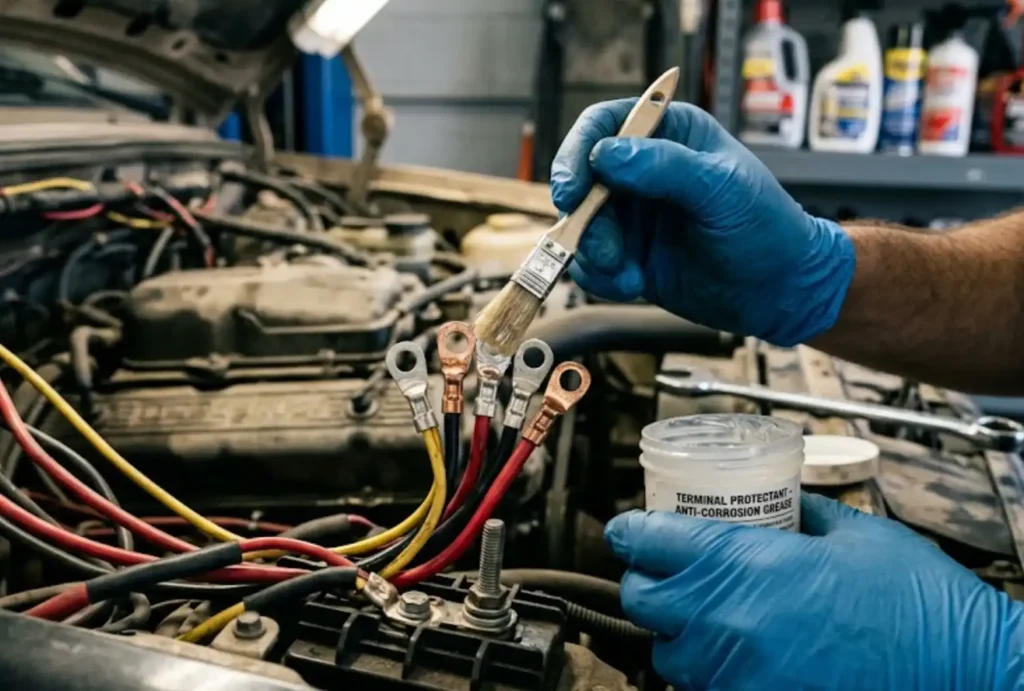
The same terminal can face three very different risks
A dry control room, an outdoor cabinet and a coastal or chemical site need different evidence. Treat the examples below as triage routes, then qualify the complete assembly for the actual location.
Control workmanship and contamination
Confirm conductor compatibility, strip length, terminal condition, clean assembly and the enclosure’s normal ventilation. Investigate any residue or localized heat instead of automatically adding grease.
Control water paths and dew point
Specify the complete enclosure, entries and seals; evaluate thermal cycling and condensation; and choose terminal materials whose datasheets cover the operating temperature and environment.
Demand environment-specific evidence
Identify the actual salt or chemical species, exposure pattern and cleaning process. Review cyclic salt-mist, corrosion-resistance or application evidence without treating test hours as a service-life promise.
Practical rule: remove the electrolyte or contaminant path first; material, compound and coating choices come after the exposure is understood.
Direct answer
Corrosion is a failure mechanism—not a color
Terminal block corrosion develops when susceptible materials meet moisture or another electrolyte, oxygen or reactive chemicals, and enough time. Dissimilar metals in electrical contact can accelerate attack when an electrolyte bridges them. The visible deposit is only evidence; the engineering task is to find the path that created it and decide whether the current-carrying interface is still trustworthy.
Break the corrosion conditions
Exclude liquid and corrosive vapors, avoid unqualified metal combinations, preserve the designed contact force, and keep residues away from the current path. Layered controls are more dependable than a single spray or coating.
Is the connection still fit for service?
Compare the finding with the terminal manufacturer’s criteria, baseline measurements, load and neighboring phases. If the clamping surface, plating, spring, screw, conductor or insulation is damaged, replacement is safer than cosmetic cleaning.
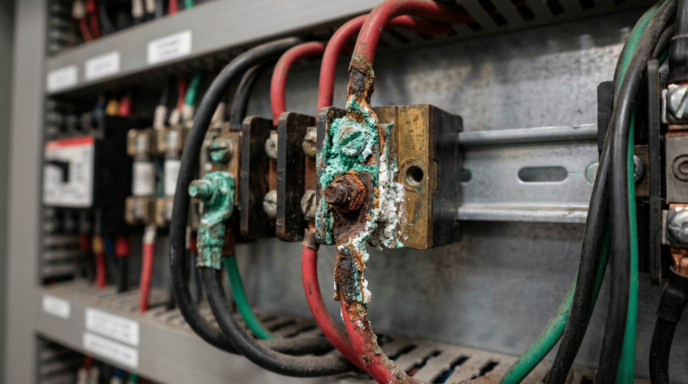
| Finding | Possible mechanism | Evidence to collect | Safe next decision |
|---|---|---|---|
| Green or blue deposit near copper | Moisture plus salts, acids or other contaminants reacting with copper alloy | Water path, chemical exposure, deposit location, plating condition and adjacent hardware | Isolate the source; replace if the contact zone or conductor has metal loss or uncertain integrity |
| White deposit at an aluminum conductor | Aluminum corrosion, often associated with moisture, preparation or connector incompatibility | Exact conductor alloy, terminal marking, approved preparation and compound instructions | Do not rework by habit; follow the connector manufacturer or replace with a qualified system |
| Rust on screws, rail or enclosure hardware | Water ingress, condensation, damaged finish or unsuitable hardware | Entry points, gasket compression, drainage, fastener material and spread beyond the visible rust | Correct the environment and replace affected parts where function or bonding may be impaired |
| Darkening, melting or recurring hotspot | High resistance, overload, loss of contact force or corrosion-related heating | Load, conductor size, installation record, comparison with similar phases and manufacturer limits | Remove from service under the applicable safety procedure and investigate before re-energizing |
Acceptable values depend on the exact connection, measurement method, current, temperature and baseline. Trend like-for-like readings and use the manufacturer’s acceptance criteria. For a deeper workflow, see the SENTOP guide to terminal block contact resistance.
Method 1 · Define before selecting
Map the exposure and remove the corrosion path
A corrosion-resistant terminal is not a universal material label. Its suitability depends on the surrounding atmosphere, deposits, wetting pattern, temperature, connection design and enclosure. Begin with an exposure map that procurement, panel design, installation and maintenance teams can all use.
Find how the electrolyte arrives
Check direct rain, hose direction, leaking conduit, capillary entry, cold surfaces, temperature swings, unsealed doors and drain paths. A high ingress rating does not prove that condensation cannot form inside.
Name the actual chemical
Salt aerosol, sulfur compounds, chlorine-bearing cleaners, ammonia, process dust and conductive deposits behave differently. Record concentration or source, exposure duration, cleaning chemicals and whether the enclosure draws plant air.
List every metal in the current path
Include conductor, ferrule or lug, terminal contact, screw or spring, busbar, bonding hardware and rail. Galvanic risk requires an electrical connection and an electrolyte; geometry and relative exposed area also influence severity.
Protect contact force over time
Vibration, conductor movement, thermal cycling, over-temperature and poor strain relief can disturb the interface or damage seals. Record maximum load and ambient conditions rather than qualifying from nominal current alone.
IEC 60721-3-3 provides a framework for classifying environmental conditions at stationary, weather-protected locations. IEC 60068-2-11 and IEC 60068-2-52 describe salt-mist tests used to compare resistance or reveal coating defects under defined laboratory conditions. These documents can strengthen a specification, but a test result is not an automatic prediction of years in service. Ask how the test specimen, severity and acceptance criteria relate to the shipped terminal and your installation.
Draw the exposure boundary
Mark outdoor/indoor transitions, washdown directions, chemical sources, cold surfaces, drains, cable routes and pressure differences. Include storage and commissioning conditions if equipment may sit unpowered.
Capture the operating envelope
Record ambient and internal temperature, duty cycle, conductor current, altitude where relevant, vibration and maintenance access. Use realistic extremes and simultaneous conditions.
Define verification evidence
State which datasheet limits, application approvals, material information and environmental tests must apply to the exact catalogue number and accessories—not merely to a product family.
Write “suitable for this documented environment with evidence for the exact model and complete installed assembly,” then attach the environment sheet. Avoid substituting a preferred metal, coating name or salt-spray duration for application proof.
Method 2 · Qualify the entire interface
Specify a compatible terminal–conductor system
Choose the exact terminal model only after the environment is known. The current path includes more than a headline contact metal: base alloy, plating system, geometry, spring or screw mechanism, conductor preparation, accessories and housing all affect performance. A premium-sounding material is not evidence that the complete connection is suitable.
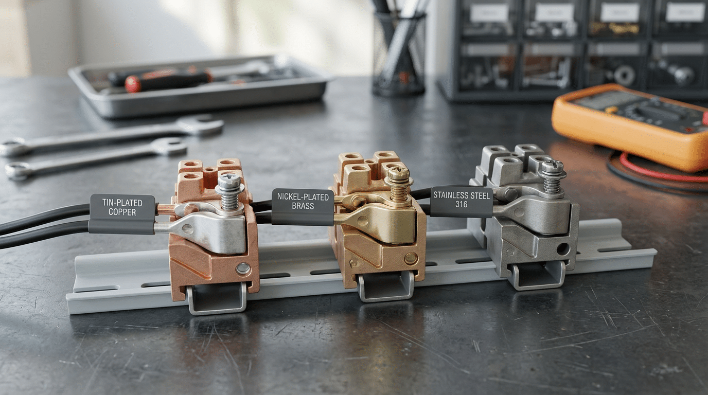
| Decision | Evidence for the exact model | Warning sign |
|---|---|---|
| Conductor compatibility | Permitted copper or aluminum type, solid/stranded/flexible class, cross-section, ferrule or lug rules and strip length | The catalogue says “universal” but the detailed instructions cover only copper or one conductor class |
| Contact and plating | Base metal and coating information, rated current/temperature, environmental test or application statement, mating accessories | A generic alloy claim without coating thickness, exact product scope or connection-system evidence |
| Housing and accessories | Temperature class, flammability data, chemical/UV suitability where required, end plates, partitions, markers and rail compatibility | Assuming one polymer grade resists every cleaner, outdoor exposure or process vapor |
| Approval and test scope | Certificate or database entry that maps the exact type, conductor range, ratings and production site to the target market | Using a logo, salt-spray photo or family brochure as proof for an unlisted variant |
Control dissimilar-metal interfaces instead of applying a voltage shortcut
AMPP describes galvanic corrosion as accelerated attack that can occur when dissimilar materials are electrically coupled in a corrosive electrolyte. There is no universal “safe voltage gap” for every terminal connection because the electrolyte, temperature, metal area ratio, coatings and geometry change the result. Prefer a connector system expressly designed for the conductor combination, limit moisture at the interface, and preserve the manufacturer’s plated contact system.
Do not infer that stainless steel should replace the current-carrying contact simply because it resists rust, or that matching visible colors means the metals are compatible. Electrical conductivity, contact force, plating behavior, temperature rise and approvals still govern. Use the terminal block material and model selection guide to develop the electrical requirements before adding the corrosion controls.
“PA66,” “V-0” or “UV resistant” does not establish compatibility with a specific chemical, temperature, outdoor exposure or certification. Request the exact material and application data.
Define the evidence needed for the risk and supply chain. A certificate format that is not part of the product’s normal control plan may add paperwork without proving contact performance.
Method 3 · Preserve the designed contact
Install exactly as documented—and use compounds only when approved
A suitable terminal can still fail when the conductor is damaged, stripped to the wrong length, contaminated, clamped outside the intended zone or tightened with an uncontrolled tool. Corrosion prevention therefore begins with repeatable workmanship and traceable instructions, not with adding a general-purpose grease.
Use the specified conductor condition
Confirm conductor metal, class and cross-section. Follow the required strip length and ferrule or lug treatment. Do not nick strands, leave insulation under the clamp or expose unnecessary bare conductor.
Keep the interface clean and aligned
Protect terminals from dust, metal chips, moisture, skin oils and process residues. Insert the conductor fully, use the correct tool and verify that strain is not transferred to the contact.
Follow the connection technology
For screw connections, use the specified torque and tool where the manufacturer requires it. For spring technologies, use the stated actuation method. Never apply screw-terminal habits to a maintenance-free spring connection.
Record what was actually installed
Capture terminal part number, conductor, tool or torque method, installer, date and any approved compound. This baseline makes later inspection far more useful than an isolated photograph.
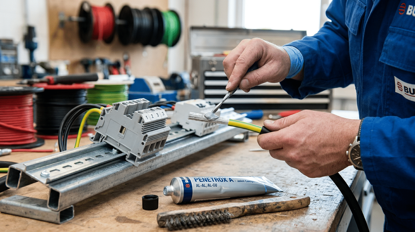
Why “add dielectric grease” is not a universal method
A compound can change insertion, friction, torque-tension behavior, insulation compatibility, current path contamination and approval conditions. Some terminals are designed for dry copper conductors; some exact models permit aluminum only with a named preparation and paste. For example, WAGO’s published material instructions limit aluminum use to identified series and define conductor form, Alu-Plus paste, temperature and current conditions. That is a model-specific permission—not a general endorsement for applying paste to every spring or screw terminal.
Before using grease, oxide inhibitor, anti-seize or contact cleaner, obtain written instructions that identify the exact terminal series, conductor metal and class, allowed product, application location and amount, temperature limits, approval implications and any inspection or retermination steps. If that chain is missing, keep the designed contact clean and dry.
Likewise, do not automatically abrade plated contact parts or re-torque every connection after a fixed number of hours. Abrasion can remove engineered plating, and additional tightening can damage the conductor or mechanism. Use the terminal manufacturer’s current installation and maintenance instructions, supported by the equipment owner’s qualified electrical maintenance program.
Method 4 · Protect the assembled system
Control ingress, condensation and chemicals with the complete enclosure
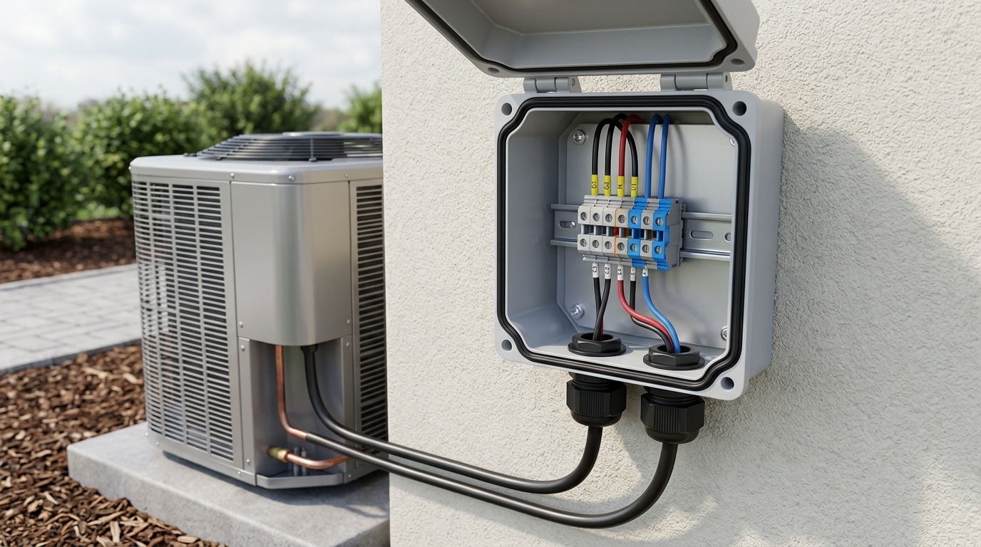
The enclosure—not the terminal block alone—usually provides the first barrier against rain, spray, dust and plant atmosphere. Its performance depends on the box, door, gasket, glands, conduit entries, plugs, vents, drains, mounting and maintenance condition as one assembly.
| Evidence | Useful for | Does not prove by itself |
|---|---|---|
| IEC 60529 IP code | Defined degrees of protection provided by an enclosure against access, solid foreign objects and water | Corrosion resistance, chemical compatibility, condensation control or equivalence to a NEMA enclosure type |
| NEMA 250 enclosure type | North American enclosure requirements that may include conditions beyond IP tests, depending on type | A reversible one-to-one conversion from an IP code; NEMA explicitly warns there is no complete equivalence |
| IEC 60068 salt-mist result | Comparison under a defined continuous or cyclic laboratory exposure and stated acceptance criteria | A universal outdoor, offshore or service-life duration for every assembled panel |
| IEC 60721 environment class | A structured way to describe environmental conditions for a location and use case | Automatic qualification of a terminal, gland, coating or enclosure without product evidence |
Design every opening and every thermal cycle
- Cable entries: select glands for the cable diameter, material, thread, installation orientation and target enclosure rating. Tighten and inspect them according to the gland manufacturer; seal unused openings with compatible rated devices.
- Gaskets and doors: protect sealing surfaces from damage, paint, debris and cable interference. Verify door alignment and latch compression after field wiring.
- Condensation: model or measure internal temperature and dew-point risk across operating and shutdown cycles. Choose a qualified heater, climate control, drain or pressure-equalization solution when the design calls for it; no single device is mandatory for every sealed box.
- Chemical exposure: check enclosure, gasket, gland and window compatibility with the exact process vapor and cleaning chemical. If possible, relocate or positively separate the cabinet from the source.
For a deeper selection route, compare outdoor terminal block IP ratings and the complete-system guidance for waterproof terminal blocks in junction boxes. Coastal projects should also review SENTOP’s guide to salt-spray resistance in ship and port power systems.
Use conformal coating only as a qualified, controlled process
Conformal coating is primarily a controlled process for printed wiring or electronic assemblies. It is not a general-purpose film to spray across serviceable terminal contacts. NASA-STD-8739.1 requires electronic assemblies to be clean and demoisturized before polymeric application and protects electrical contact surfaces from cleaning residue. For a terminal assembly, mask separable contacts, conductor clamping zones, test points, spring or screw mechanisms, mating interfaces and release features unless both the terminal manufacturer and coating process explicitly approve the design.
Coating chemistry, thickness, cure, cleanliness, adhesion, repair method and inspection criteria must come from the selected coating’s technical data and a validated process. IPC-HDBK-830 describes broad coating considerations; it does not make one 25–75 μm thickness range correct for every chemistry and assembly. Potting or heat-shrink may also block inspection, heat dissipation or rework. Treat them as engineered design choices, not maintenance shortcuts.
NEMA explains that its enclosure types include requirements not addressed by the IP code and that conversion is directional, not a complete equivalence. Specify whichever system the project and authority require, then verify corrosion, sealing, drainage and climate controls separately.
Method 5 · Detect change before failure
Inspect by risk, trend the evidence and replace when integrity is uncertain
There is no defensible universal six-month inspection or one-to-three-year re-torque rule for every terminal. Set tasks and intervals from equipment criticality, environment, duty, observed deterioration, manufacturer instructions, applicable standards and the facility’s electrical maintenance program. Shorten the interval when evidence changes; lengthen it only through documented risk review.
Stable, dry and accessible
Use the manufacturer and site program as the baseline. Verify cleanliness, enclosure condition and representative connections during planned work, then retain photographs and records for comparison.
Outdoor, wet, vibrating or thermally cycled
Inspect seals, entries and condensation evidence more frequently than low-risk assets. Trend loaded temperature or electrical measurements only with a defined method and comparable operating conditions.
Corrosive chemicals, salt, recurring ingress or critical loads
Use an engineered maintenance plan with clear acceptance criteria, qualified personnel, controlled shutdown access and corrective-action triggers. Consider environmental monitoring or sampling where visual checks cannot characterize exposure.
OSHA 1910.333 requires live parts to be de-energized before work unless specific exceptions apply, and de-energized circuits must be controlled and verified under the required procedure. Never use an aerosol’s dielectric-strength claim as permission to clean, spray or tighten an energized terminal. Energized thermography or testing requires the site’s qualified-person, shock and arc-flash controls.
A practical inspection sequence
Review history before opening
Check previous photographs, defects, load changes, water events, cleaning changes, enclosure work and recurring alarms. Define the task, boundaries and acceptance criteria before shutdown.
Inspect the environmental barrier
Look for water marks, damaged gaskets, loose or mismatched glands, blocked drains, filter condition, rust paths, salt deposits and failed climate-control devices. Correct the source, not only the terminal symptom.
De-energize, lock/tag and verify
Follow the employer’s applicable energy-control and electrical safe-work procedure. Account for stored energy and every possible source before touching conductors or applying any cleaning method.
Compare the connection with its baseline
Record deposits, metal loss, plating damage, discoloration, cracked or softened insulation, conductor movement and mechanism condition. Use consistent photographs and instrument methods where measurements are part of the plan.
Apply the documented disposition
Replace, reterminate or clean only under approved instructions. Do not re-torque maintenance-free connections or “touch up” a screw merely to reach the original installation torque unless the current manufacturer procedure calls for that action.
Replace rather than cosmetically restore when:
- corrosion, pitting or plating loss reaches the conductor or terminal contact zone;
- the spring, screw, clamp, cage, lug or conductor has lost material, force, thread integrity or dimensional control;
- the housing is carbonized, melted, cracked, crazed, chemically softened or no longer retains the terminal safely;
- the approved conductor/terminal/compound combination cannot be confirmed;
- temperature or electrical behavior remains abnormal after the environmental cause is corrected; or
- the manufacturer’s inspection or re-use criteria are not met.
Do not use a universal pitting depth, micro-ohm value, temperature rise or percentage trend as an automatic pass/fail criterion. Establish thresholds from the equipment design, validated baseline and manufacturer or engineering authority. SENTOP’s terminal block maintenance checklist can help structure the record, but site safety and product instructions remain controlling.
Implementation
Turn the five methods into a release-and-maintenance file
The useful deliverable is not a list of products. It is a traceable file linking the real environment to the exact terminal system, installation process, enclosure design and maintenance decision. Use the gates below for a new panel or a corrective upgrade.
Five gates before the connection enters service
| Record | What to include | Owner |
|---|---|---|
| Environment and duty | Location, water/condensation route, chemicals or salt, temperature, vibration, current and criticality | System or panel designer |
| Connection release | Terminal part number, conductor, accessories, datasheets, approvals, material/environment evidence and substitutions | Engineering and procurement |
| Work instruction | Strip length, preparation, tool or torque, compound only if approved, inspection points and installer record | Production or installer |
| Enclosure verification | Rating system, box, glands, plugs, seals, mounting, climate control, commissioning inspection and field changes | Panel builder and commissioning |
| Maintenance baseline | Initial photographs or measurements, task and interval basis, safe-work method, triggers and replacement disposition | Asset owner |
A change in conductor class, plating, base alloy, resin, gland, enclosure, compound, supplier site or cleaning chemical can change the corrosion risk. Re-run the affected approval gate instead of assuming the original evidence still applies.
Send the exposure data, and SENTOP can help shortlist the connection
For a useful review, include the conductor, electrical ratings, connection technology, installation location, enclosure, temperature, water or condensation path, salt or chemical exposure, approvals, annual quantity and destination market. SENTOP can then compare suitable terminal families and identify evidence that still needs validation.
Move from environment to the right terminal family
Terminal Blocks
Compare mounting, connection method and circuit function before narrowing exact models.
Review the range → Selection workflowChoose the Right Terminal
Define electrical, conductor, mechanical, environment and approval requirements together.
Build the specification → Outdoor designIP Rating Guide
Connect water and solid ingress risks to the complete enclosure around the terminals.
Review outdoor protection → Project evidenceQuality and Service Support
Plan model selection, sample review, documentation and order support with SENTOP.
Review support →Go deeper on water, salt, resistance and maintenance
Terminal block corrosion prevention FAQ
What causes corrosion on electrical terminal blocks?
Corrosion needs a susceptible material and an environment that supports the reaction, commonly moisture or another electrolyte plus oxygen or reactive contaminants. Salt, process gases, conductive dust, cleaning residues and condensation can accelerate attack. Dissimilar metals that are electrically coupled in an electrolyte can form a galvanic cell. Poor sealing, incompatible materials and loss of contact force often turn the environmental exposure into an electrical problem.
Can I put dielectric grease on every terminal block?
No. Apply a grease or oxide-inhibiting compound only when the terminal manufacturer approves the exact product or material type for the exact series, conductor and operating conditions. A compound can affect friction, torque, insulation, spring mechanisms, contamination and approvals. If the manufacturer specifies a dry copper connection, keep it clean and dry rather than adding a general-purpose product.
Does an IP66 enclosure prevent terminal corrosion?
No. IP66 addresses defined dust and water-jet ingress tests for the enclosure; it does not by itself establish corrosion resistance, chemical compatibility or condensation control. Performance also depends on the installed glands, plugs, gasket, mounting, door condition and field modifications. Match the complete assembly to the actual exposure and manage internal dew-point risk separately.
Is NEMA 4X the same as IP66?
No. NEMA states that there is no complete equivalence between NEMA enclosure types and IEC IP codes. A NEMA type may meet or exceed certain IP ingress requirements, but NEMA 250 includes additional considerations—such as corrosion-related requirements for some types—that IP codes do not cover. Specify the system required by the project, product standard and authority, without using a reverse one-to-one conversion.
How often should terminal blocks be inspected or re-torqued?
Use the exact terminal and equipment manufacturer instructions plus a risk-based electrical maintenance program. Environment, duty, criticality and previous findings determine the tasks and interval. Many spring connection products are described as maintenance-free; screw connections also should not be blindly tightened back to installation torque. Inspect and act under a qualified safe-work procedure.
Can I clean or spray a corroded terminal while it is energized?
Do not treat a spray’s dielectric rating as authorization for energized work. OSHA 1910.333 requires de-energization before work on or near live parts unless defined exceptions apply, along with the appropriate lockout/tagout and verification steps. Follow the employer’s electrical safety program and product instructions. Replace damaged connections when their integrity cannot be demonstrated.
Standards and authoritative sources
- AMPP — Galvanic Corrosion: mechanism of dissimilar materials electrically coupled in a corrosive electrolyte.
- IEC 60721-3-3:2019: environmental classification for stationary use at weather-protected locations.
- IEC 60529: degrees of protection provided by enclosures under the IP Code.
- NEMA — Enclosure Types FAQ and NEMA Enclosure Type conversion guidance: limits of IP/NEMA comparisons.
- IEC 60068-2-11:2021 and IEC 60068-2-52:2017: continuous and cyclic salt-mist test methods.
- WAGO — Material Specifications: manufacturer-specific conditions for copper and identified aluminum-conductor connections.
- Phoenix Contact — Terminal Block Material Tests: examples of product-level corrosion and environmental testing.
- NASA-STD-8739.1: cleanliness, demoisturization and controlled polymeric application on electronic assemblies.
- IPC-HDBK-830A: guidance for design, selection and application of conformal coatings.
- OSHA 29 CFR 1910.333: electrical safe-work, de-energization and lockout/tagout requirements.
- NFPA 70B (2026): current standard for electrical equipment maintenance; use the applicable adopted edition and facility program.
Technical references define test methods, safety requirements and selection principles; they do not certify a SENTOP product by association. Verify each exact terminal model, conductor, accessory, enclosure and approval scope before release. This guide does not replace the authority having jurisdiction, the equipment manufacturer or the employer’s electrical safety program.
