
12-Way / 24-Contact Terminal Block Strip: A 20A Selection Guide
A “12-way, 24-contact, 20A” label describes only part of the product. Learn what the numbers usually mean, what they do not prove, and which drawing, conductor, jumper, torque, mounting and approval details must match before purchase.
Choose the exact part—not the marketplace title
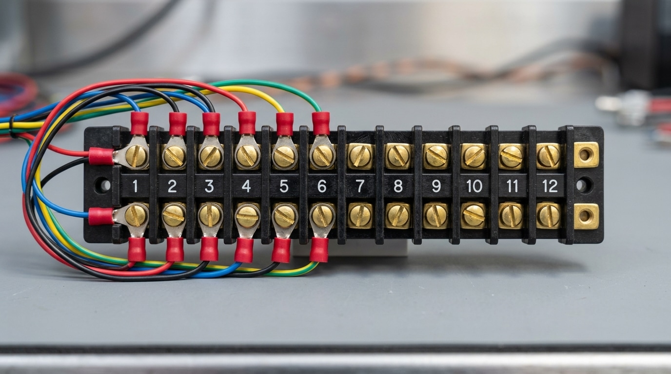
A 12-position dual-row barrier strip normally provides 12 isolated electrical nodes and 24 screw termination points. In a typical feed-through layout, the two terminals at one numbered position share one electrical node; neither side has a fixed “input” or “output” direction. However, the product drawing—not the appearance—must confirm that topology.
Ratings such as 20A, 300V and 22–12 AWG belong to a specific catalog number and its stated test conditions. Before specifying the strip, verify the position map, maximum contact rating, voltage, permitted wire and terminal type, pitch, screw thread, torque, mounting, compatible cover or jumper, environmental limits and approval record.
The most important correction: 12 isolated nodes are not the same as 12 complete circuits. A basic DC load normally needs at least a supply and return node. Likewise, a strip marked 20A must never be treated as a 12 × 20A distribution bus unless the exact product and complete assembly documentation explicitly support that design.
Three numbers, three different questions
Product listings often compress topology and rating into a short phrase. Expand that phrase before comparing parts. “12 way” addresses the number of positions, “24 contact” often counts termination points, and “20A” describes an electrical limit under defined conditions.
- Position, pole and way are often used interchangeably in catalogs, but the drawing should show what is actually isolated.
- Contact may be informal sales language for a screw termination point. Do not confuse the count with a certified current rating.
- Dual row describes the physical arrangement. It does not prove whether opposite terminals are connected or whether positions can be bridged.
- 20A does not tell you the allowed wire, voltage, ambient temperature, simultaneous-loading condition or end-use approval.
Similar format, different current rating
These two manufacturer examples share the same 12-position, dual-row, dual-barrier format and 9.53 mm pitch. Yet one is published at 20A and the other at 15A. That difference is why appearance and pole count cannot approve a substitute.
| Official example | Positions / format | Published maximum current | Voltage | Wire range | Pitch / screw |
|---|---|---|---|---|---|
| TE 1-1546306-2 | 12 positions, 2 rows, dual barrier, wire-to-wire | 20A maximum contact rating | 300V | 22–12 AWG / 0.3–3 mm² | 9.53 mm / 6-32 |
| Molex 389771012 | 12 circuits, 2 rows, dual barrier | 15A maximum per contact | 300V | 12–22 AWG / 0.33–3.31 mm² | 9.53 mm / see drawing |
Values above identify those exact catalog numbers as published by their manufacturers; they are examples, not substitute specifications for a SENTOP or third-party part. Always open the latest product drawing and current agency record before design release.
Do not add the positions together. “20A maximum contact rating” does not establish a 240A strip rating, authorize all positions to operate at the maximum simultaneously, or define the capacity of a jumper-fed common bus. Ambient temperature, conductor, termination, adjacent loading, enclosure and approval conditions may all matter.
What to verify before ordering
A complete comparison needs electrical, mechanical and compliance data. If a marketplace listing omits an item, request the manufacturer drawing or choose a traceable alternative.
Internal connection map
Confirm that opposite screws at each numbered position are bonded and adjacent positions are isolated. Check how any removable or permanent bridge changes that map.
Current and voltage conditions
Record the exact model rating, AC or DC applicability, temperature and loading conditions. Do not infer 600V from body material or 20A from product shape.
Conductor and termination
Verify copper or aluminum permission, solid or stranded construction, AWG or mm² range, insulation limits, strip length, terminal type and number of conductors per point.
Pitch, screw and geometry
Measure center-to-center pitch—not overall length. Match ring or fork tongue dimensions only when that termination is permitted, and verify cover clearance.
Mounting method
Confirm panel holes, mounting centers, fasteners, PCB pins or DIN adapter. Check required creepage, clearance and spacing to grounded metal in the finished assembly.
Torque and tooling
Use the value marked on the product or stated in its instructions and an approved torque method. Never guess from screw size or copy a value from a similar strip.
Environment and enclosure
Check operating temperature, vibration, corrosion, condensation, pollution, flammability and enclosure needs. A surrounding IP enclosure does not create an unclaimed marine or automotive rating.
Approvals and accessories
Match the certification record to the exact part and end use. Specify approved covers, jumpers, markers and separators from the same compatible system.
A row is not a bus until the design makes it one
A normal dual-row feed-through strip isolates one numbered position from the next. To create a common supply, only use a bridge or jumper that the manufacturer identifies for that series, pitch and rating—or another wiring method explicitly allowed by the documentation.
A 20A claim at one position does not let a single 20A input feed twelve 20A loads. The feeder, first terminal, bridge segments and protective device must all be evaluated for the combined current.
Pitch alone is insufficient. Check mechanical fit, insulation, current, voltage and the number of bridged positions.
A terminal strip is a passive connection point, not a fuse or circuit breaker. Smaller downstream conductors may need separate overcurrent protection.
Land more than one conductor under a screw only when the terminal marking, drawing or instructions expressly permit that conductor combination.
Use durable markers and a wiring diagram that show bonded positions, bridged groups, polarity, source and protective-device assignment.
Useful format, conditional suitability
A barrier strip can organize multiple connections, but the words “12-way” and “20A” do not qualify it for every panel, vehicle, boat or outdoor installation.
Protected equipment panels
Potentially suitable as a fixed wire-to-wire junction where the exact ratings, wiring method, spacing, touch protection, mounting and end-product rules are satisfied.
LED and low-voltage distribution
Useful as a documented connection point when source classification, conductor sizing, polarity, circuit separation, voltage drop and branch protection are engineered separately.
Audio speaker circuits
Possible when voltage, current, conductor and enclosure requirements match. Low-level or shielded signal paths need additional grounding, shielding and crosstalk analysis.
Automotive harnesses
Require validation for vibration, shock, temperature, chemicals, wire support and the vehicle installation. A general industrial barrier strip is not automatically automotive-qualified.
Marine systems
Check corrosion, moisture, mounting location, system standard and—where fuel vapor may be present—ignition-protection requirements. An open strip is not inherently marine-rated.
Outdoor enclosures
The finished enclosure must address ingress, UV, condensation and temperature, while the terminal still needs documented suitability inside that enclosure. IP belongs to the evaluated assembly.
Barrier strip, Eurostyle, DIN rail or PCB?
No style wins every application. Select the termination and mounting architecture first, then compare exact model ratings and accessories.
| Style | Best matched to | Typical advantage | Verify before selection |
|---|---|---|---|
| Dual-row barrier strip | Fixed multi-position wire-to-wire junctions | Clear position separation; some models accept ring or fork terminals | Internal map, terminal permission, pitch, screw, cover, torque and mounting centers |
| Eurostyle fixed strip | Compact direct-wire connections | Simple wire entry and compact packaging | Clamp type, conductor preparation, strip length, ratings and mounting |
| DIN-rail modular block | Expandable industrial panel wiring | Flexible pole count, markers, bridges and functional blocks | Rail system, end plates, stops, bridges, width, approval and panel SCCR context |
| PCB barrier terminal | Wire-to-board equipment interfaces | Direct connection to the circuit board | Pin layout, board material, solder process, spacing, mechanical support and field wiring rating |
Explore SENTOP's barrier terminal block range, broader terminal block portfolio and terminal block accessories. Availability and ratings must still be confirmed against the requested model.

Wire the documented connection
Installation details vary by terminal mechanism. The safe workflow is therefore specification-led, not based on a generic strip length or torque chart.
De-energize and verify
Follow the site's qualified electrical-safety procedure, isolate all sources and verify absence of hazardous voltage before touching conductors.
Confirm the exact part and drawing
Match the label, position map, conductor range, terminal method, jumper arrangement and enclosure layout to the released design.
Prepare the permitted conductor
Use the specified wire construction, strip length and terminal or ferrule only when allowed. Match any crimp terminal and tooling as one qualified system.
Install approved accessories
Fit compatible bridges, covers, separators and markers in the sequence stated by the manufacturer. Do not improvise a jumper from a similar pitch.
Tighten to the stated value
Use the product marking or instructions and an approved torque method. Do not guess from #6 or #8 screw size, and do not routinely re-torque unless instructed.
Inspect, test and document
Check conductor capture, clearance, polarity, labels and strain relief; perform the specified continuity or quality checks before controlled energization.
Six shortcuts that create expensive mismatches
Calling 24 termination points “24 ways”
This doubles the apparent circuit count. State 12 positions, two termination points per position, and attach the conductive-path drawing.
Buying by amperage alone
A 20A label does not settle voltage, wire range, simultaneous loading, temperature, termination type, approvals or the finished equipment's requirements.
Assuming every row is common
Adjacent positions are normally isolated until a compatible bridge joins them. Treat a common bus as a designed current path, not a visual property.
Copying torque from another strip
Body shape and screw diameter do not establish torque. Under-tightening and over-tightening can both compromise the connection.
Using certification logos without a record
Verify the exact catalog number, file, category and conditions. A UL Recognized Component is not the same as a standalone UL Listed end product.
Assuming an enclosure fixes the environment
An enclosure helps manage ingress, but it does not create missing vibration, corrosion, temperature, marine, automotive or ignition-protection qualifications.
Send enough data to match the part once
A photo or the phrase “12-way 20A” is not a complete specification. A drawing, BOM line or sample plus the following information lets a supplier check both fit and rating.
SENTOP can review a model reference, terminal photo, panel drawing, wiring requirement or bill of materials and discuss compatible terminal blocks, covers, jumpers, markers and packaging.
Include these fields
- Required number of isolated positions
- Internal connection or jumper map
- System voltage and AC/DC
- Maximum and normal branch current
- Number of simultaneously loaded positions
- Wire AWG or mm² and construction
- Copper or aluminum conductor
- Bare wire, ring, fork or other termination
- Pitch and screw or stud dimensions
- Mounting method and available space
- Cover, marker and bridge requirements
- Ambient and enclosure conditions
- Required approvals and target market
- Drawing, reference part or sample photo
- Annual quantity and order quantity
- Labeling and grouped-packaging needs
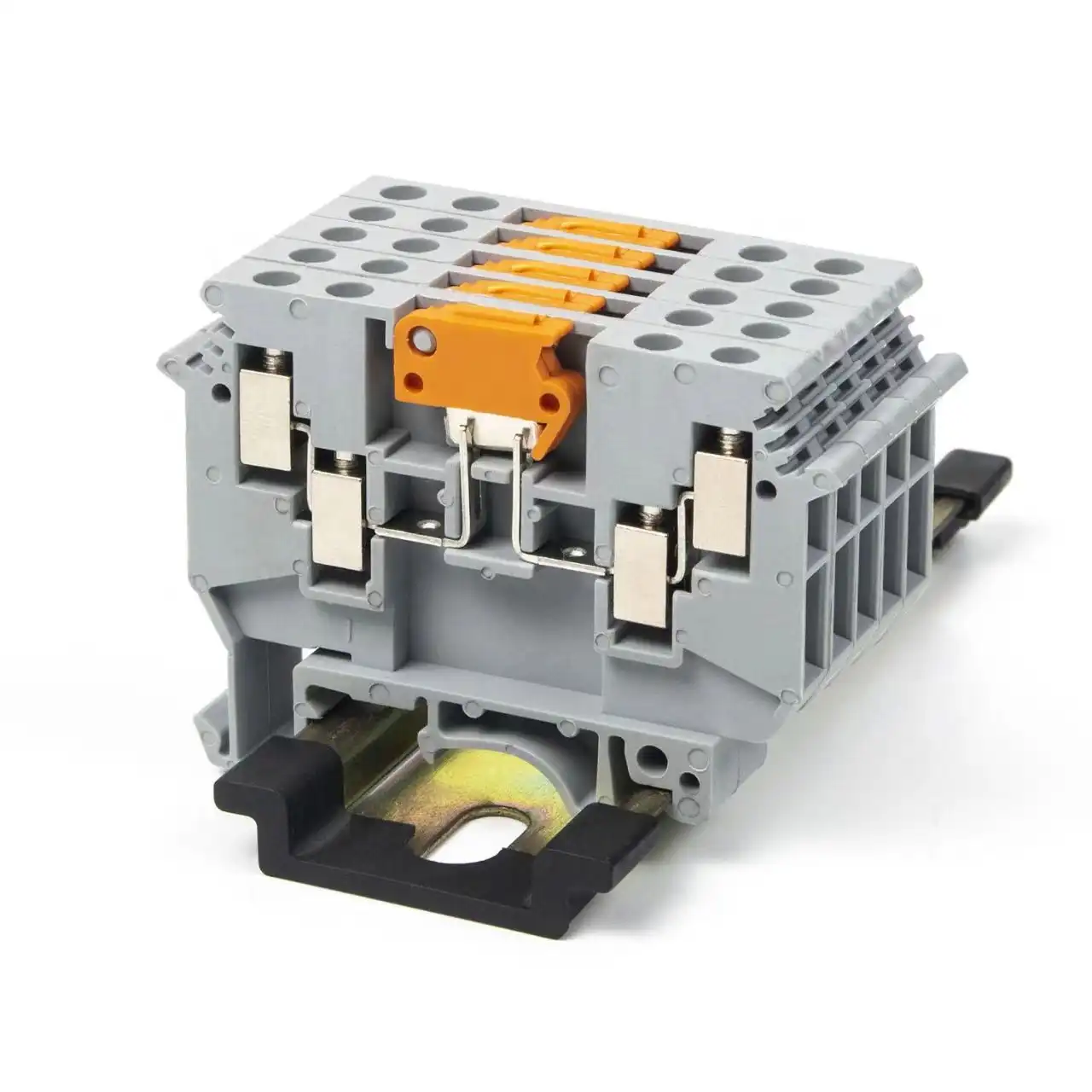
Need a 12-way terminal block matched to your drawing?
Send the electrical ratings, conductor, pitch, termination, jumper plan, mounting, environment, approvals and quantity. SENTOP can help narrow the correct series and accessories before sampling.
Related terminal block guides
12-way terminal block FAQ
Is a 12-way terminal block the same as a 24-contact terminal block?
It can describe the same physical strip when each of 12 positions has two screw termination points, for 24 points in total. The safer description is 12-position dual-row barrier strip with 24 screw termination points. Confirm the exact conductive path because 24-contact is not a universal topology definition.
Does a 20A rating apply to each way or to the whole strip?
Check the exact datasheet wording. A manufacturer may publish a maximum current per contact or position, but that is not an aggregate strip rating and must not be multiplied by 12. Simultaneous loading, ambient, conductor, jumper and approval conditions can limit the completed design.
What wire size fits a 20A 12-way terminal block?
There is no universal wire range for this product description. One TE 12-position example permits 22–12 AWG, while another similar family may differ. Verify the exact part's permitted conductor size, material, solid or stranded construction, terminal type and strip length.
Can I use a jumper to create a common bus?
Yes, only when the manufacturer identifies a compatible bridge or expressly permits the wiring method. Evaluate the sum of downstream branch currents through the common segment, and provide appropriate feeder and branch overcurrent protection. The terminal block itself is not a protective device.
How do I measure terminal-block pitch?
Measure from the center of one position to the center of the adjacent position. Do not divide the overall molded length by the position count because end walls and mounting ears add length. A dimensioned drawing is more reliable than a photo or ruler estimate.
What torque should I use on the terminal screws?
Use the value marked on the exact product or stated in the manufacturer's instructions, applied with the specified or approved method. Never choose torque solely from screw size or a similar-looking strip, and re-tighten later only when the instructions require it.
Can a standard barrier strip be used outdoors, in a vehicle or on a boat?
Only after the exact part and finished installation are qualified for the environment. Check enclosure, moisture, condensation, temperature, vibration, corrosion, chemicals and applicable end-use requirements. A 20A rating or an IP enclosure alone does not create automotive, marine or ignition-protection approval.
What should I send a supplier for model matching?
Send a drawing, reference part or clear photos together with position count, connection map, voltage, current and loading, wire details, termination type, pitch, screw, mounting, jumpers, covers, environment, approvals, quantity and packaging needs.
Sources used for verification
Manufacturer pages support only the exact examples named. Approval scope and current certification details should be checked again when a part is released for production.
- TE Connectivity 1-1546306-2 product record — 12-position, dual-row example with 20A maximum contact rating.
- Molex 389771012 product record — similar 12-circuit format published at 15A maximum per contact.
- Cinch barrier block Series 140/141/142 datasheet — shows rating changes across related pitches and screw sizes.
- UL 1059, Sixth Edition scope — terminal block standard scope and end-product suitability limitation.
- UL Product iQ — database for checking the exact certification record, file and category.
- UL Component Recognition guidance — distinction between a recognized component and a listed end product.
- SENTOP barrier terminal blocks — product-family overview and project matching entry point.
- SENTOP combined terminal blocks — modular and bridging context for multi-position connections.
Engineering note: This article is a selection framework, not installation authorization. Use the latest manufacturer documentation, certification record, local rules and qualified engineering review for the finished equipment.

