
Uimp
Peak prescribed impulse withstand under specified conditions. It does not clamp a surge or set continuous operating voltage.

Rated impulse withstand voltage, or Uimp, is the declared peak of a prescribed impulse that a terminal block can withstand under stated test conditions. It is not working voltage, surge protection, SCCR or a whole-panel lightning guarantee. Read the full condition row, not the kV number alone.
Uimp is the peak value of an impulse of prescribed form and polarity. The product must withstand it without failure under stated test conditions. Clearance is referenced to this value within the applicable insulation rules.
The rating belongs to the exact product and evaluated arrangement. Read it with the conductor-to-earth voltage, overvoltage category, pollution degree and altitude. Also check the product standard, terminal function, mounting and accessories. A look-alike or detached kV value is not proof of equivalence.
Capture the field name, value, unit, condition suffix and standard basis. Do not translate every value into a generic voltage or kA claim.
Switching and lightning coupling can cause short transients. Some terminal test data cites a 1.2/50 microsecond impulse. The applicable standard sets the wave, limits, polarity sequence, test points and pass rules. Longer temporary overvoltage is a separate stress. Some fault conditions can cause this longer stress, which Uimp does not establish.
The graphic is a normalized teaching image. It is not the current standard text and it does not prove that a product passed. Do not build or apply an impulse source from this article.
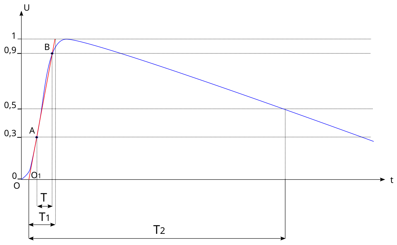
Do not calculate Uimp from a fixed multiple of working voltage. First set the conductor-to-earth voltage and overvoltage category under the applicable rules. This gives the required Uimp. Then use Uimp, field shape and altitude to check clearance. Use working or insulation voltage, pollution degree and material group to check creepage. IEC 61000-4-5 is an EMC surge test, not an insulation-withstand test.
The visible terminal body is only one part of the insulation path.
The shortest path through air. Required separation is tied strongly to expected impulse stress, field geometry and altitude.
The shortest path along an insulating surface. Working voltage, pollution degree and material group or CTI are central inputs.
The path through insulating material. Thickness, material, manufacture, ageing and the product test basis all matter.
Adjacent terminals, rail, barriers, plugs, jumpers and function blocks can create the governing path.
A room that looks clean does not prove the surface condition. Overvoltage category describes circuit location and expected transients. It is not a product quality grade. Use the deeper guides to pollution degree and terminal-block creepage and clearance for those separate decisions.
Lightning can be one source of a transient. The stress at a terminal also depends on the network, coupling, protection design and gear location. A standard impulse is a controlled test. It is not a replay of a weather event.
Lower air density can reduce clearance withstand. IEC 60664-1 addresses normal use up to 2,000 m and provides guidance above that level. Check the manufacturer's baseline and the actual site elevation.

Treat the manufacturer data sheet as a matrix. Keep every condition attached to its value.
Return to the original manufacturer document. Do not select the most favorable row unless the project actually meets that row's category, pollution, altitude, construction and approval basis.
Use a product page only for that exact product, revision and condition.
Phoenix Contact ST 1,5 BK product data places nominal voltage, rated surge voltage, category and pollution information in the insulation data.
Lesson: copy the complete row, not only the kV entry.
Phoenix Contact PT 16 N has its own condition-based data. A higher value is not a universal rule or quality rank.
Lesson: product family and terminal function stay attached.
WAGO 2002-1201 shows distinct approval columns. A matching kV or voltage number does not make the routes interchangeable.
Lesson: verify the destination market.
Case size, color and apparent spacing are not a data sheet. Similar bodies can hide other geometry, material, barriers or certification terms. Record the full part number before comparing Uimp, Ui, conductor, current or fault duty.
Panel feed-through and connector pages can list several build cases. Older pages may cite earlier IEC editions. They can show why condition rows vary. They do not prove conformity to a newer edition.

IEC 60947-7-1:2025 and UL 1059 Sixth Edition are distinct product routes. UL 840 applies only when an end-product or certification route calls it up. It does not approve each terminal by default. UL 1059 component compliance also does not prove end-product fit.
The released construction, accessories and potential relationships decide whether the component evidence applies.
| Assembly item | Why it matters | Evidence to request |
|---|---|---|
| Adjacent potentials | Mixed voltage levels can create the governing air or surface path. | Approved terminal plan and manufacturer arrangement guidance. |
| DIN rail or support | Terminal-to-rail insulation can be part of the verification. | Selected rail/support and mounting documentation. |
| End plates and covers | They may complete the housing or maintain a required separation. | Exact compatible accessory numbers. |
| Partitions and barriers | A missing or substituted separator can change spacing. | Required part, location and usage statement. |
| Jumpers and feed-ins | They change potential and current relationships and can limit ratings. | Accessory data and released strip configuration. |
| Fuse, disconnect, PE or electronic terminals | Internal geometry and applicable product evidence differ from a feed-through block. | Individual data for every functional terminal. |
Do not replace the rail, terminal function, barrier, jumper or mating half by appearance. Review temperature rise, current path, insulation coordination and fault duty. Also check the assembly's declared conformity or certification. Use the separate terminal-block SCCR guide for the U.S. panel method.
Laboratory systems create dangerous high-voltage impulses with controlled energy, waveform and measurement chains. The pictured equipment serves high-voltage transmission-component work, not this terminal-block test.
Do not perform field impulse or hipot testing from a blog. Testing can damage insulation, electronic modules or connected equipment if the exact procedure, disconnections and acceptance criteria are not established by the responsible manufacturer and standard.

A coordinated design can include both, but neither component replaces the other.
Only a documented system design and applicable standard can set the residual stress and required insulation level. A high-Uimp terminal does not remove the need for surge protection. Read SPD Up, VPR and device-type data in the surge protective device range under their own standards.
This is a documentation and engineering sequence, not an installation or test procedure.
Identify the end-product, installation and target-market standards before choosing terminal ratings.
Record topology and conductor-to-earth voltage, not only a nominal line voltage.
Document overvoltage category, pollution degree, altitude, enclosure and micro-environment assumptions.
Record the SPD and protection architecture without using it as a generic Uimp override.
Name the terminal, rail, end plates, barriers, jumpers, feeds, plugs and special functions.
Compare Uimp, Ui, rated voltage, category, pollution, altitude, approval and accessory notes.
Issue the BOM, terminal plan, data sheets, approval record, verification plan and change-control rule.
Do not inject test voltage into installed gear from this article. Only qualified persons may inspect, replace or test parts. Follow the maker's instructions and site procedure. Find and isolate every source. Control stored and backfed energy. Apply the required lockout/tagout controls. Use rated test gear to confirm that exposed parts are de-energized.
"6 kV terminal" is not a complete specification.
The supplier confirms that the exact terminal and listed accessories meet the project's insulation rules in the offered arrangement. The record must cite current manufacturer data and approval evidence. Use the full terminal-block RFQ checklist for the commercial handoff.
The answers define selection boundaries and must remain tied to the visible FAQ schema.
No. Uimp is a transient insulation-withstand rating under specified impulse-test conditions. Operating or nominal voltage describes ordinary service. Both fields must suit the application, and the Uimp number must not be compared directly with continuous circuit voltage.
Not automatically. The terminal must still match the required category, pollution degree, altitude, Ui or rated voltage, current and thermal duty, function, accessories and approval route. A higher kV value does not replace a complete application match.
Uimp concerns a prescribed short impulse. Ui is the voltage to which dielectric tests and creepage distances are referenced under the product rules. They address related insulation questions but are not substitutes.
Many terminal data sheets use rated surge voltage for a Uimp-style insulation field. Confirm the manufacturer's exact label, product standard, test context and condition suffix. Do not confuse it with an SPD voltage protection level.
No. Uimp describes insulation withstand and does not clamp or divert surge energy. Downstream protection requires a designed architecture using suitable protective devices and equipment-level coordination.
Not by itself. A lower value is justified only when the documented system coordination and applicable standard establish the residual stress and required insulation level for that location.
Do not assume so. Air-clearance withstand is affected by altitude. Check the manufacturer's declared baseline, the site elevation and the applicable correction or approval route.
Only when the product type, function, conditions, standard basis and installed arrangement are comparable. A common kV value does not prove equivalent insulation behavior.
Different categories, pollution degrees, material conditions, panel-wall cases or accessories can produce different documented ratings. Select only the row that matches the real project condition.
No. Current rating concerns the thermal contact path under defined conditions. Impulse insulation concerns voltage stress, clearance, creepage, material, environment and construction. Verify both independently.
Send the terminal plan, system voltage, category, pollution degree, altitude, SPD architecture, target market and exact offered parts.
