
The most favorable of the listed IEC material groups for tracking resistance. Other design inputs still govern.
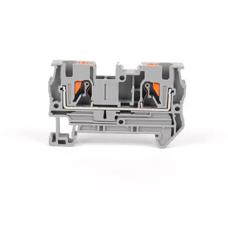
Insulation coordination · Material evidence
How Insulation Material and CTI Affect Terminal Block Safety
Insulation material affects tracking resistance, heat aging, flame behavior, mechanical stability, and environmental durability. Comparative Tracking Index (CTI) is one controlled material-test result. It can help establish a material group for creepage selection, but it is not a terminal voltage rating, a clearance value, or proof that a finished panel is safe.
MaterialUse the exact grade, color, thickness, and molded-part record
GeometryVerify creepage, clearance, solid insulation, and accessories separately
AssemblyMatch voltage, pollution, altitude, environment, and end-product rules
Direct answer
CTI is one input—not a terminal safety score
CTI compares how a solid insulating material resists surface tracking under the IEC 60112 test. A CTI result can place the material in an IEC material group. The applicable insulation-coordination or product standard may then use that group, together with working voltage and pollution degree, when determining a creepage requirement.
The result does not directly provide a safe creepage distance. It does not determine clearance through air, solid-insulation thickness, rated impulse withstand voltage, conductor current, temperature rise, flame performance, chemical resistance, or mechanical life. Those questions need their own data and the exact terminal-block construction.
The practical rule is simple: specify the approved terminal assembly, not a resin family or CTI number. Confirm the exact part number, material record, electrical conditions, microenvironment, geometry, accessories, product approval, and finished-equipment requirements before release.
Tracking mechanism
What CTI measures—and what it does not
Surface tracking is the progressive formation of a conductive path across an insulating surface. Electrical stress, moisture, ionic contamination, heat, and surface damage can contribute to the process in service. IEC 60112 applies a controlled liquid-contaminant test to solid-insulation specimens and reports Comparative Tracking Index (CTI) or Proof Tracking Index (PTI).
CTI is comparative: it helps classify material behavior under the stated test. PTI is a proof result at a selected test condition. Neither is a complete terminal-block qualification. IEC 60112:2025, corrected in February 2026, explicitly warns that its results are not directly suitable for evaluating safe creepage distances in electrical apparatus.
Do not reverse-engineer a product rating from a material value. The material formulation, molded surface, ribs, barriers, end plates, contamination, voltage distribution, and governing standard all affect the real insulation path.

Classification
Use IEC material groups only inside the applicable design method
The thresholds below classify material tracking performance. They are not terminal voltage bands, quality grades, or a universal creepage chart. CTI is determined using IEC 60112; IEC 60664-1 uses the result to assign insulating-material groups within its applicable creepage method.
A defined material-group input—not a stand-alone terminal voltage rating.
A broad IEC band that spans two UL 746A PLC bands. Do not translate labels mechanically.
Use only within the exact governing table, pollution condition, geometry, and product rating.
IEC language
Material groups I, II, IIIa and IIIb
The IEC grouping uses CTI bands of ≥600, 400–<600, 175–<400, and 100–<175. The correct creepage result still depends on the applicable insulation-coordination or product standard.
UL language
UL 746A Performance Level Categories
UL PLC 0 is ≥600; PLC 1 is 400–<600; PLC 2 is 250–<400; PLC 3 is 175–<250; PLC 4 is 100–<175; PLC 5 is <100. IEC Group IIIa therefore covers both PLC 2 and PLC 3.
Never convert an IEC group into a UL PLC from the label alone. Confirm the underlying test method, exact material record, thickness/color conditions where applicable, and the rule used by the end-product standard.
CTI 600 is not a 600 V rating. It is a material-test classification at the upper IEC 60112 test level—not permission to operate a terminal block at 600 V.
Insulation coordination
Creepage, clearance, and solid insulation are three different checks
CTI can influence one input in a creepage calculation. It does not collapse the insulation system into one number.
| Insulation concept | What it describes | Main design inputs | Does CTI decide it? |
|---|---|---|---|
| Creepage distance | The shortest path along an insulating surface between conductive parts. | Maximum steady-state RMS working voltage across the specific path, pollution degree, material group where invoked, insulation function, surface geometry, and governing standard. A nameplate or Ui value is not automatically the voltage across every path. | CTI can affect the material-group input, but it does not independently set the distance. |
| Clearance | The shortest path through air between conductive parts. | Required impulse withstand voltage, overvoltage conditions, the applicable pollution-degree rule, electric-field geometry, altitude correction, and the product/end-equipment method. | No. CTI is not an air-gap rating. |
| Solid insulation | The insulating material through a wall or body between conductive parts. | Material properties, thickness, construction, voltage stress, manufacturing control, aging, and required tests. | No. CTI is a surface-tracking result. |
| Installed terminal row | The assembled blocks, support, end parts, bridges, covers, conductors, and adjacent potentials. | Exact approved configuration, environment, shortest real paths, and end-product obligations. | No. The full assembly needs review. |
Material test
Use the exact IEC 60112 or UL material record—not a generic resin claim.
Classification
Assign the applicable IEC material group or UL PLC without translating one system loosely.
Governing rule
Identify the product and end-equipment standard plus insulation function.
Required geometry
Apply voltage, pollution, impulse, altitude, and surface-path conditions.
Assembly validation
Verify the exact terminal, accessories, mounting, conductors, and panel record.
IEC 60664-1:2020+AMD1:2025 covers low-voltage insulation coordination within its stated scope. Its base altitude is 2,000 m, with guidance for higher altitudes. Never transfer a table or correction factor without confirming that the product and end-equipment standard actually use it.
For the distance-design workflow, continue with SENTOP's terminal block creepage and clearance guide. This article deliberately keeps CTI in its narrower role as one material input.
Geometry matters
A favorable material group cannot rescue the wrong housing geometry
Terminal pitch, molded ribs, barrier height, conductor entry, screw or spring access, open sides, adjacent potentials, and the installed end parts determine the physical paths that matter. A compact terminal with a high-CTI material can still be unsuitable if the declared voltage, pollution, impulse, or assembly conditions do not match the project.
The reverse is also true: a lower material group is not automatically unsafe. A manufacturer can use longer paths, barriers, spacing, or another verified construction to achieve a published product rating under defined conditions. Select from the exact datasheet and approval—not by ranking polymer names.
Do not field-create insulation geometry. Cutting ribs, omitting end plates, adding tape or coating, inserting an undocumented empty terminal, or mixing accessory families can alter the evaluated path. An unqualified coating, tape, or empty position does not justify a lower pollution degree or spacing credit. Use only the manufacturer-approved construction or a protection system evaluated under the method invoked by the governing standard.

Separate evidence streams
Insulation material has more safety jobs than CTI
A defensible material review keeps surface tracking, flame behavior, thermal aging, dielectric performance, environment, and mechanical retention separate.
Tracking resistance
Relative material behavior in the IEC 60112 surface-tracking test; an input to material grouping, not a finished-product rating.
UL 94 flammability
Small-specimen flame behavior at a stated grade, color, and thickness. V-0 is not “fireproof” and does not establish CTI.
Glow-wire / ignition evidence
GWFI and GWIT are material results, while an end-product glow-wire test evaluates a finished part. Use the result type required by the governing rule rather than substituting one for another.
Long-term thermal aging
UL RTI is property-specific—electrical, mechanical impact, or mechanical strength—and can depend on grade, color, and thickness. IEC TI follows a different route. Neither is a terminal ambient rating, temperature-rise limit, or clamp-retention rating.
Dielectric / solid insulation
Through-material voltage stress under stated thickness and geometry. It does not replace surface tracking or air-clearance analysis.
Humidity, chemicals, UV
Retention of properties under the actual agent, concentration, temperature, duration, condensation, and enclosure conditions.
Mechanical stability
Molded geometry, barriers, mounting, and conductor-clamp function must remain stable through service stress and production variation.
Contact pressure through insulation
IEC 60947-7-1:2025 adds testing for constructions where contact pressure is transmitted through insulating material. Exact scope and product evidence control.
Material identity
“PA66,” “PBT,” or “PC” is not a complete specification
Polymer-family names help describe chemistry. They do not freeze the electrical, fire, thermal, environmental, or mechanical behavior of a finished molded part.
Fillers and flame retardants
Reinforcement and additives can change tracking, strength, thermal behavior, moisture response, and process control.
Color and exact grade
A certification record can be limited by exact grade, color, thickness, and manufacturer. Do not extend one formulation to another.
Walls and surface condition
Thickness, knit lines, ribs, surface finish, contamination, and production control affect the real insulating construction.
More than one material
A housing, lever, insert, plug interface, barrier, or accessory can use different polymers. Identify the material governing each critical path.
Read product data at the part and path level. Ask which exact material and physical path govern line-to-line, line-to-PE, power-to-control, or another required separation. Current product examples show why: one terminal can publish different CTI groups for its housing and actuator while its insulation-coordination table uses the group assigned to the governing path. Neither the best nor the least favorable material anywhere in a device can be generalized to the whole terminal.
If the exact terminal's certified product rating already covers the application, the manufacturer may control the material group without publishing it separately. Escalate when material group is an input to the claimed insulation coordination, or whenever the product rating, path, environment, or configuration remains unresolved.
Microenvironment
Pollution degree describes the insulation surface—not just the room
Dust, humidity, condensation, salt, oil, process chemicals, conductive residue, and cleaning practices can change the microenvironment around a terminal. An indoor enclosure does not automatically guarantee a clean, dry insulation surface. Ventilation, cable entry, heating/cooling cycles, maintenance, and nearby processes all matter.
A high CTI does not prove resistance to every chemical or prevent condensation. It also does not establish an IP or NEMA rating for the completed enclosure—and an enclosure label alone does not establish the microenvironment at a particular insulation path. Define the actual agent, concentration, temperature, duration, UV exposure, deposits, cleaning residue, and contamination pattern; then request material-retention and product evidence for that condition.
- Condensation: review thermal cycles, dew point, drainage, climate control, and enclosure strategy.
- Conductive dust: consider deposits, cleaning method, service intervals, and barriers.
- Chemicals and oils: identify the exact substance and exposure, not a generic “chemical resistant” claim.
- Heat and UV: verify long-term material retention and the actual terminal temperature/current conditions.

Completed terminal row
The most restrictive verified path controls the assembly
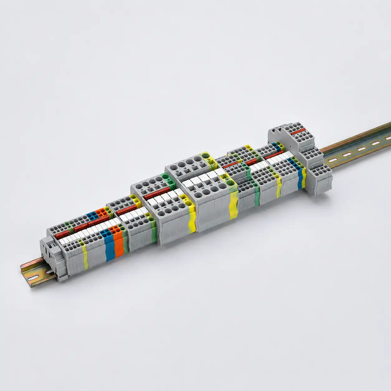
A terminal row can combine feed-through, protective-earth, disconnect, fuse, multi-level, sensor, and distribution terminals. It can also include end plates, partitions, bridges, covers, markers, and end stops. These parts change adjacency, exposed sides, surface paths, conductor routing, and access.
Verify the exact sequence and manufacturer-approved accessories. A matching color or rail fit is not evidence of insulation compatibility. End plates and partitions perform defined functions; they do not automatically make a row suitable for a higher voltage, a harsher pollution degree, or another product family.
For North American projects, a UL Recognized Component can carry Conditions of Acceptability that the finished equipment must satisfy. Under UL 1059, compliance with the component standard does not by itself prove suitability for every end-product use. The panel, machine, or distribution assembly needs its own governing evaluation.
Change-control trigger: a new material, color, molding site, terminal revision, accessory, terminal sequence, or environmental condition can affect the evidence set. Require a documented review instead of approving a same-fit substitute.
Seven-step review
Move from a CTI claim to an approved terminal assembly
This is an engineering, procurement, and compliance workflow. It is not a field-modification or energized-work procedure.
Identify the end product and approval route
Record the panel, machine, appliance, infrastructure, rail, marine, hazardous-location, or other application; target countries; and the exact product and assembly standards.
Map every insulation interface
Define line-to-line, line-to-neutral, line-to-PE, power-to-control, and any functional, basic, supplementary, or reinforced separation that the design requires.
Establish electrical stress
Record AC/DC, working-voltage pairs, rated insulation voltage where applicable, Uimp, overvoltage category, source/surge assumptions, frequency, and altitude.
Define the microenvironment
State pollution degree, humidity, condensation, conductive dust, chemicals, oils, salt, UV, temperature cycling, cleaning, and enclosure controls.
Shortlist exact product records
Compare the complete catalog number, material group or CTI where relevant, creepage/clearance conditions, conductor/current data, flame/thermal evidence, environmental limits, and certification scope.
Verify the completed row
Check adjacent blocks, DIN rail or support, end plates, partitions, bridges, covers, markers, conductor routing, clearances, and the installation configuration named by the manufacturer.
Freeze the evidence and control changes
Release the BOM, drawing, accessory list, data sheets, approval files, limitations, inspection criteria, and revision. Any substitution returns to documented review.
Application scenarios
The same CTI can lead to different decisions
These composite examples show why the application and exact construction determine the release decision.
Compact geometry
Verify the exact material group, working-voltage interface, pollution degree, impulse condition, adjacent potentials, end parts, and published row configuration. Do not buy the highest CTI and assume the pitch is suitable.
Condensation and residue
Combine CTI with climate and chemical evidence, enclosure strategy, cleaning method, and documented pollution assumptions. A material group cannot override an uncontrolled surface environment.
High current density
Prioritize temperature rise, conductor and clamp data, RTI/TI evidence where applicable, molded-geometry retention, ventilation, and ambient limits. CTI does not set continuous current or temperature.
Separate fire evidence
Follow the end-product rule for UL 94, glow-wire, ignition, thickness, and configuration. V-0 and CTI answer different questions; neither alone is a finished-product fire approval.
Same fit, different evidence
Compare geometry, exact material record, approvals, accessories, electrical conditions, environment, and manufacturing change controls. Resin name, CTI, color, and rail fit do not establish interchangeability.
Claims to reject
Eight shortcuts that create false confidence
“CTI 600 means the terminal is safe.”
It is a material-test result. It does not define current, clearance, environment, assembly geometry, or end-product compliance.
“CTI determines clearance.”
Clearance is an air-path question driven by impulse, overvoltage, geometry, altitude, and the governing standard—not CTI.
“V-0 proves high tracking resistance.”
UL 94 flammability and IEC 60112 tracking use different test methods and measure different hazards.
“Every PA66 grade behaves the same.”
Formulation, filler, flame retardant, color, thickness, molding, aging, and surface condition can change the declared performance.
“The material card approves the row.”
A material record does not verify terminal geometry, support, adjacent blocks, accessories, conductors, or finished-equipment conditions.
“A component mark approves the panel.”
Component certification has a defined scope and conditions. The completed assembly still needs its governing evaluation.
“Tape, coating, or a spacer fixes it.”
An undocumented field change can alter geometry, materials, inspection, and approval assumptions. Use only an OEM-approved configuration.
“Higher CTI is always the best buy.”
Choose the exact terminal that meets the real application. A higher material group does not compensate for wrong conductor, current, environment, accessory, or approval data.
Stop-use boundary
Carbonized insulation is a replacement decision—not a cleaning task
If a terminal shows carbonized tracking, arc marks, cracked or melted insulation, abnormal heat, conductor movement, or repeated insulation or ground-fault operation, quarantine the affected circuit.
Cleaning, paint, tape, added coating, or re-tightening does not restore the evaluated insulation system. Replace affected parts and heat-damaged conductors as the manufacturer requires, then correct the root cause before re-energizing.
Qualified-person response
- Identify every normal, alternate, stored-energy, and backfeed source.
- De-energize and apply the required lockout/tagout procedure.
- Verify absence of voltage with suitable test equipment.
- Record the damaged terminal, adjacent parts, conductors, load, and environment.
- Replace rather than cosmetically repair carbonized, cracked, melted, or arc-damaged insulation.
- Investigate electrical stress, termination, contamination, heat, spacing, and material/configuration evidence before release.
Standards boundary
Keep material tests, product standards, and end-product approval separate
| Standard or record | Relevant role | What it does not prove alone |
|---|---|---|
| IEC 60112:2025 + COR1:2026 | Comparative and proof tracking tests for solid insulating materials. | A safe creepage distance, terminal voltage rating, or environmental qualification. |
| IEC 60664-1:2020+AMD1:2025 | Low-voltage insulation-coordination framework for creepage, clearance, and solid insulation within its scope. | Automatic applicability to every product or a substitute for the product/end-equipment standard. |
| IEC 60664-3:2016 | Insulation coordination for assemblies using coating, potting, or molding for protection against pollution where the governing route invokes it. | Spacing credit for ordinary tape, paint, an empty position, or another unevaluated field change. |
| IEC 60947-7-1:2025 | Specified terminal blocks and test-disconnect terminal blocks for round copper conductors on a support, mainly for industrial or similar use. | Approval of every connector type, aluminum conductors, the complete panel, or an undocumented terminal row. |
| IEC 60947-7-4:2019 | Specified PCB terminal blocks for copper conductors, including soldered and press-in connections within its scope. | Permission to treat PCB and support-mounted terminal standards as interchangeable. |
| UL 746A / UL 94 / UL 746B | Short-term polymer properties, flammability classification, and long-term thermal aging, respectively. | One universal material score or finished-terminal/end-product certification. |
| UL 840 | North American insulation-coordination methods where the governing end-product standard references them. | Permission to apply its tables outside the applicable product and certification route. |
| UL 1059, Edition 6 | Terminal-block component requirements and defined use conditions. | Suitability in every end product; additional end-product evaluation can still be required. |
Evidence does not move upward automatically. Material methods (IEC 60112, UL 746A, UL 94, UL 746B), insulation-coordination methods (IEC 60664-1 or UL 840 when invoked), terminal product standards, the exact certification record, and the completed end-product evaluation are separate layers.
Certification scope matters. Confirm the exact catalog number, approval/file status, material record, ratings, accessories, and Conditions of Acceptability. A standard logo, material certificate, or supplier statement is not universal permission to alter the panel design.
RFQ evidence pack
Ask for an exact terminal solution—not a material slogan
Send enough information for the supplier to compare the offered terminal, insulation paths, accessories, environment, and approval route with the actual application.
- End product and target countries
- Applicable product/assembly standards
- Exact terminal function and part number
- AC/DC and working-voltage pairs
- Ui, Uimp, OVC where applicable
- Pollution degree and altitude
- Insulation function and adjacent potentials
- Current, conductor, and ambient
- Humidity, condensation, dust, chemicals, UV
- Exact material/CTI or group evidence
- UL 94, glow-wire, RTI/TI if required
- Rail, end plates, partitions, bridges, covers
- Approval/file and Conditions of Acceptability
- Samples, first article, traceability, PCN/PDN
- Drawing, BOM, quantity, destination
Frequently asked questions
Terminal block insulation material and CTI questions
Does a higher CTI always mean a safer terminal block?
No. A higher CTI indicates better relative surface-tracking resistance in the IEC 60112 test and can affect material-group selection for creepage. Terminal safety still depends on voltage, pollution degree, impulse stress, clearance, altitude, thermal/current duty, environment, geometry, and the approved assembly.
Does CTI determine terminal-block clearance?
No. CTI relates to surface tracking and a material-group input for creepage analysis. Clearance is the shortest path through air and is determined from impulse or surge conditions, overvoltage category, geometry, altitude, and the applicable standard.
Can I calculate creepage distance from CTI and voltage alone?
No. IEC 60112 states that CTI results are not directly suitable for evaluating safe creepage in apparatus. You must know the governing standard, working-voltage definition, pollution degree, insulation function, material group, geometry, and complete configuration.
Is UL 94 V-0 enough to prove insulation safety?
No. UL 94 classifies small-specimen flame behavior under stated grade, color, thickness, and test conditions. It does not establish CTI, creepage, clearance, dielectric strength, chemical compatibility, thermal lifetime, or finished-product fire approval.
Are IEC CTI material groups and UL 746A PLC interchangeable?
No. They use related tracking data but different classification bands and certification records. IEC Group IIIa spans UL PLC 2 and PLC 3. Confirm the exact test method and the rule referenced by the product or end-product standard.
Should I specify a resin family in a terminal-block RFQ?
Specify the exact terminal part and required performance evidence first. A resin-family name does not control formulation, color, thickness, molded geometry, material group, flame class, thermal behavior, or accessory compatibility. Name a material only when the qualified design or governing standard requires it.
Can two V-0 terminal blocks have different CTI values?
Yes. V-0 is a flammability classification, while CTI evaluates relative resistance to surface tracking. Terminals can share a V-0 classification while using materials with different CTI values or groups. Review each record under its stated conditions.
Why do humidity and chemicals matter if CTI is high?
CTI is a standardized comparative test, not proof that a molded terminal retains its properties under every chemical, humidity, condensation, salt, or cleaning exposure. Request exact climate and compatibility data for the agent, concentration, temperature, and duration.
Does a terminal-block component approval cover the complete control panel?
No. Component approval is evidence under defined conditions. The finished terminal row and panel still need the applicable assembly or end-product review, including adjacent parts, mounting, wiring, environment, and Conditions of Acceptability where relevant.
When should insulation material selection be escalated?
Escalate for unusual AC or DC voltage, high altitude, condensation, conductive contamination, chemical, salt or UV exposure, high temperature or current density, fire-sensitive products, hazardous locations, rail, marine, medical applications, or any material and accessory substitution.
Primary technical sources
Current references behind the decision boundaries
Use the latest exact product data and the locally applicable end-product requirements for every released design.
- IEC 60112:2025, Corrected Version 2026-02 — CTI and PTI test methods and design limitation
- IEC 60664-1:2020+AMD1:2025 CSV — low-voltage insulation coordination
- IEC 60664-3:2016 — pollution protection by coating, potting, or molding within its scope
- IEC 60947-7-1:2025 — specified terminal blocks for round copper conductors
- IEC 60947-7-4:2019 — PCB terminal blocks for copper conductors
- UL 746A, Edition 6 — short-term property evaluations and CTI PLC
- UL 94, Edition 7 — small-specimen flammability classification
- UL 746B, Edition 5 — polymeric material long-term property evaluation
- UL 840 — clearances and creepage where referenced by the governing standard
- UL 1059, Edition 6 — terminal blocks and end-product suitability limitation
- UL Solutions — Comparative Tracking Index and IEC material-group thresholds
- UL Solutions — property-specific Relative Thermal Index context
- Phoenix Contact PLW 16-6/3-10 PA13 — path-level material-group example
- Phoenix Contact SPT-THR 1,5/11-H — multi-material path-level example
- Weidmüller — manufacturer-specific terminal-block insulation materials
- WAGO — formulation-specific material data and conditions
- UL Solutions — Component Recognition and Conditions of Acceptability
- OSHA 1910.333 — de-energization, lockout/tagout, and verification for workplace electrical tasks



