
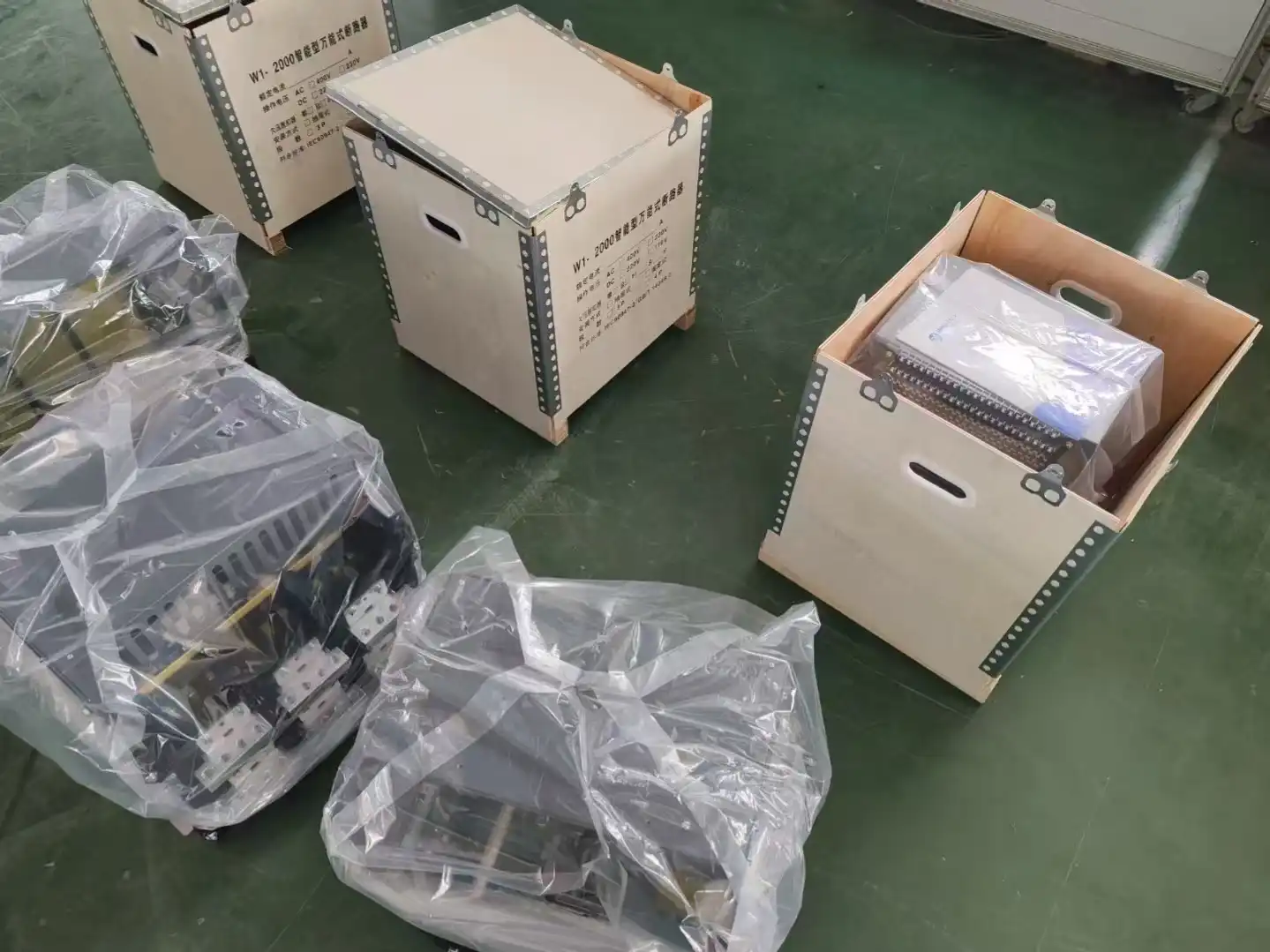
ACB vs MCCB: Choose by Circuit Role, Fault Duty, and Service Needs
Air circuit breakers are often shortlisted for main incomers, bus ties, and serviceable switchgear. Molded-case circuit breakers are often shortlisted for compact feeders and machine distribution. Those are useful tendencies—not current cutoffs. The defensible choice comes from the exact circuit role, voltage, available fault current, breaker and assembly ratings, trip functions, selectivity evidence, mounting plan, and market approval.
Choose by system evidence, not by acronym
Put ACBs and MCCBs on the same shortlist when their published ranges overlap. Eliminate candidates with four gates, then compare the remaining architecture and lifecycle trade-offs.
What job must the breaker perform?
Define main incomer, tie, generator feeder, large distribution feeder, motor feeder, machine main, or final branch. Record critical-load consequence and planned expansion.
Can the exact installation clear and withstand the fault?
Use the point-of-installation fault study. Match the breaker ratings at the actual voltage and check the switchboard, panel, or machine assembly rating.
Can the selected trip unit meet the study?
Confirm the exact long-time, short-time, instantaneous, ground-fault, neutral, metering, communication, and interlocking functions and their approved setting ranges.
Which mounting and service strategy fits?
Compare fixed, plug-in, or drawout construction; access, spares, outage windows, interlocks, control power, maintenance scope, and replacement plan.
ACBs commonly occupy high-current main and tie positions, while MCCBs commonly occupy compact feeder positions. Product portfolios overlap, and selected MCCBs can offer electronic trips, communication, high interrupting ratings, and drawout arrangements. Some ACBs are fixed. Start with required functions and exact ratings, then choose the construction that satisfies them.
Two construction families with overlapping capability
An ACB and an MCCB both carry normal current and open under declared overcurrent conditions within their ratings. Both include an operating mechanism, contacts, arc-control structure, and a trip function. The meaningful differences are scale, enclosure and mechanism design, fault-duty evidence, configurable protection, switchgear integration, mounting, and permitted service work.
The family name alone never proves that a breaker is suitable for isolation, selective with another device, electronically protected, drawout, serviceable, remotely controlled, or certified for a target market. Under IEC 60947-2:2024, circuit-breaker classification by interrupting medium and design was removed. That reinforces a practical buying rule: identify the exact device and evidence, not only the traditional product label.
For North American projects, keep the certification routes separate. UL lists UL 489 for molded-case circuit breakers and UL 1066 for power circuit breakers. A product marketed as an “air circuit breaker” is not automatically a UL 1066 power circuit breaker, and IEC data cannot be mixed with UL data to create a more favorable hybrid rating.
What ACB and MCCB describe—and what they do not
Use these descriptions as a starting point. The exact catalog, standard record, and switchgear arrangement control the final claim.
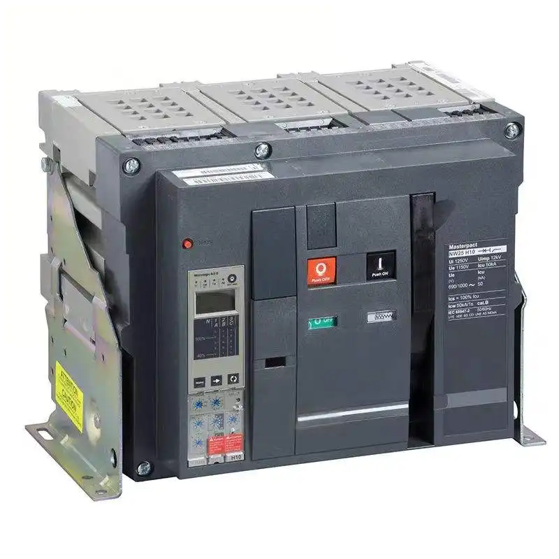
Air circuit breaker
The common industry term for a larger low-voltage breaker architecture whose main contacts interrupt current in air, normally with arc chutes that cool, divide, and deionize the arc. ACB families are often designed around switchboard mains, bus couplers, generator feeders, and large distribution feeders.
Electronic trip units, stored-energy mechanisms, remote control, fixed or drawout construction, and broad auxiliary options are common—but each remains model-specific.
SENTOP product display. Appearance does not establish rating, trip unit, mounting form, or certification. See the air circuit breaker range.
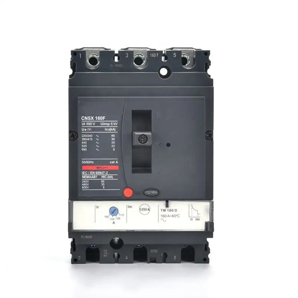
Molded-case circuit breaker
A low-voltage circuit breaker built in an integral molded insulating enclosure. MCCBs are widely used for distribution feeders, motors, equipment mains, machines, and sub-distribution panels where compact integration matters.
Thermal-magnetic and electronic trip units both exist. Selected systems can add metering, communication, zone interlocking, plug-in bases, or drawout cassettes.
SENTOP product display. Appearance does not establish rating, trip technology, mounting form, or certification. See the molded-case circuit breaker range.
| Comparison area | ACB: common tendency | MCCB: common tendency | What still needs proof |
|---|---|---|---|
| System position | Main incomers, bus ties, generator feeders, and large switchboard feeders. | Feeders, sub-distribution, motor circuits, machine mains, and dedicated loads. | The one-line, protection zones, load consequence, source study, and future expansion. |
| Construction | Larger power-breaker mechanism with visible arc-control and switchgear integration. | Compact integral molded insulating enclosure. | Exact endurance, temperature limits, terminals, accessories, and permitted maintenance. |
| Mounting | Fixed and drawout versions are common. | Fixed is common; plug-in and drawout arrangements exist in selected systems. | Cradle or cassette, interlocks, shutters, secondary contacts, approved positions, and switchgear compatibility. |
| Trip technology | Electronic trip units and extensive controls are common. | Thermal-magnetic and electronic options both exist. | Exact frame, sensor or rating plug, release, firmware, L/S/I/G functions, neutral, and accessories. |
| Selectivity role | Often used where intentional short-time delay and short-time withstand support coordination. | Often downstream; selected electronic MCCBs can also be coordinated or zone-interlocked. | The actual device pair, settings, prospective current, curves, and manufacturer tables. |
| Space and service | Larger footprint can support access, controls, test positions, and planned replacement. | Compact form can improve feeder density and simplify smaller sections. | Cabinet heat, working access, spares, outage plan, service procedure, and lifecycle cost. |
| Digital functions | Metering, event logs, communication, remote controls, and diagnostics are frequently offered. | Many electronic MCCBs offer the same broad feature categories. | Included modules, control power, protocol, security, commissioning, and data ownership. |
The table describes market tendencies, not product-family limits. An ACB is not automatically more capable, and an MCCB is not automatically simpler. Compare the exact quoted configuration.
A breaker rating is only one link in the installed fault path
Do not compare two catalog kA values until the voltage, standard, duty, poles, product configuration, and test conditions match. Then continue past the breaker: the installed switchboard, panelboard, machine, conductors, bus, and protective-device combination can impose a lower limit.
Continuous current is a separate question. Frame size, rated uninterrupted or operational current, sensor or rating plug, long-time pickup, conductor ampacity, bus rating, ambient conditions, enclosure temperature, and grouping can all be different values.
| Rating or evidence | What it means for the comparison | Common mistake to avoid |
|---|---|---|
| Ue and frequency | Interrupting and operating capability is tied to the actual voltage, frequency, pole arrangement, and sometimes grounding configuration. | Reusing a kA value from a different voltage row or regional version. |
| Frame, Iu/In, sensor, rating plug, and Ir | Mechanical frame capability, product current rating, sensing range, and long-time pickup can be different values. The current path and thermal conditions also matter. | Reading the largest frame number as the installed trip setting or conductor ampacity. |
| Icu and Ics under IEC | Icu is rated ultimate short-circuit breaking capacity; Ics is rated service short-circuit breaking capacity. Use the exact IEC product data at the actual Ue and duty. | Assuming Ics always equals Icu or comparing them to a UL interrupting rating as if the tests were identical. |
| Icw and Icm under IEC | Icw is rated short-time withstand current for a stated duration where applicable. Icm is rated short-circuit making capacity and is expressed as a peak value. | Comparing peak Icm directly with rms Icu, Ics, or Icw, or calling any high breaking-capacity breaker capable of delayed fault withstand. |
| UL interrupting rating | The marked interrupting rating applies with its voltage and certification conditions. UL 489 and UL 1066 are separate routes. | Using IEC Icu/Ics language as a direct substitute or cherry-picking the best number from each system. |
| Assembly SCCR or short-circuit rating | The complete switchboard, panel, industrial control panel, or machine can have a rating lower than an individual breaker. | Approving the installation from the breaker nameplate alone. |
| Utilization category under IEC | Category A devices are not specifically intended to obtain selectivity through intentional short-time delay and do not carry Icw. Category B devices are intended for that duty and have an Icw rating. | Assuming every ACB is Category B, every MCCB is Category A, or that Category A cannot be selective in a verified combination. |
For a deeper explanation of frame size, In/Iu, sensor or rating plug, and Ir, use the rated current of ACB guide. Do not use that page as a replacement for the short-circuit and coordination study.
Selectivity is an engineered result—not an ACB feature
An upstream device should clear only when its zone or backup role requires it. That outcome depends on the exact device pair, settings, fault level, system impedance, and manufacturer evidence.
Sustained overload protection
Long-time pickup and delay protect the intended current path under sustained loading. Confirm sensor or rating-plug relationships, conductor and bus limits, ambient and enclosure conditions, and the permitted setting range.
Delayed short-circuit response
Short-time pickup and delay can support selectivity, but the breaker must have the required short-time withstand for that duty. A delay is not permission to exceed the device or assembly rating.
High-magnitude fault response
Instantaneous protection limits delay at high fault levels. Its presence, range, or ability to be disabled is product- and rule-specific and can strongly affect coordination and incident energy.
System-specific protection
Ground-fault functions depend on sensors, neutral arrangement, grounding method, product listing, circuit role, and the approved protection design. The letter G does not prove complete coverage.
Useful only when fully engineered
Zone selective interlocking, remote control, metering, and event logs require the correct trip units, control power, point-to-point design, communication modules, configuration, and commissioning records.
Coordination is not the only objective
Intentional delay may improve continuity but can increase clearing time and incident energy. The protection study must reconcile selectivity, equipment duty, arc-energy reduction, and local requirements.
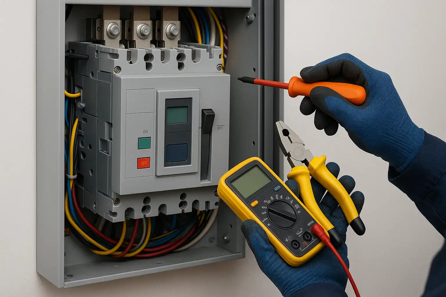
Choose the service architecture from the outage strategy
A drawout breaker can support a test position, planned replacement, access to a spare, or reduced disruption during qualified maintenance. It does not guarantee service continuity: the single-line, bus arrangement, transfer or bypass provisions, redundancy, and operating procedure determine what remains energized.
Drawout is not exclusive to ACBs. Selected MCCB systems offer plug-in or drawout cassettes, while selected ACBs are fixed. Confirm the compatible cradle, position interlocks, shutters and secondary disconnects, mechanical/electrical interlocks, racking tools, locks, spare compatibility, and controlled procedures for the exact switchgear.
A disconnected or test position is not automatically the worksite’s verified energy-isolation boundary. Before exposed work, identify every source—including utility, generator, UPS, control power, stored mechanical energy, and possible backfeed—disconnect the equipment, apply the required lockout/tagout controls, release or block stored energy, and have a qualified person verify the de-energized condition with suitable test equipment. Follow the exact OEM instructions, approved one-line, and site program. U.S. workplaces can refer to OSHA 1910.333; local law governs elsewhere.
ACBs often offer more access and more serviceable mechanisms; MCCBs often provide a compact replacement path. Neither is maintenance-free, and neither has a universal inspection interval. Use the exact product manual, operation count, fault history, environment, condition evidence, criticality, and site program.
Let the circuit role start the discussion—then let evidence finish it
These scenarios show why an ACB or MCCB may enter the shortlist. They are not universal one-line designs or current thresholds.
ACB often leads the shortlist
Main protection, extensive trip functions, deliberate short-time withstand, remote controls, drawout service, and switchboard integration can favor an ACB.
- MCCB remains possible when an exact high-performance model and compact assembly meet load, fault, coordination, and service requirements.
- Verify source fault level, main-bus rating, ground/neutral functions, assembly rating, and the full outage plan.
Architecture matters more than amperes
Stored-energy mechanisms, interlocks, controls, and short-time withstand can make an ACB attractive in complex tie schemes.
- Selected MCCBs can serve compact or lower-duty coupling arrangements when listed and engineered.
- Review source paralleling restrictions, closing duty, phase/voltage conditions, interlocks, and operating sequence.
Both families can be credible
An ACB may support a serviceable upstream protection zone. An electronic MCCB may deliver compact feeder protection, metering, and communication.
- Check motor starting, drive behavior, harmonics, source contribution, grounding, and coordination.
- Do not infer conductor protection from the breaker frame number or lug range.
MCCB often leads the shortlist
MCCB form factors often integrate efficiently into equipment, feeder, and distributed panels while retaining configurable protection.
- An ACB may still be justified by unusual main-duty, service, or fault requirements.
- Confirm equipment SCCR, enclosure thermal design, terminals, accessories, and the applicable end-product standard.
Study both source conditions
ACBs can support layered main/tie protection and maintainable switchgear; MCCBs can be appropriate at generator or downstream feeders.
- Utility and generator fault current, decrement, grounding, and protective behavior differ.
- Coordinate transfer equipment, generator protection, breaker closing duty, and load management.
Do not buy only for today’s load
Expansion can change continuous current, available fault current, protection zones, control power, network needs, spares, and outage consequences.
- Reserve space and ratings only through a documented future scenario.
- Record which assumptions trigger a new fault and coordination study.
Turn “ACB or MCCB?” into an auditable specification
Each step produces evidence for the next. If the system, fault, protection, or assembly data is missing, do not cover the gap with a product-family assumption.
Define the circuit role
Record incomer, tie, generator, feeder, motor, machine main, or branch duty; load consequence; source modes; switching frequency; and future expansion.
Describe the electrical system
Capture voltage, frequency, phase/poles/neutral, grounding, source types and impedance, available fault current, bus and conductor ratings, altitude, and environment.
Calculate load duty
Use demand, continuous and noncontinuous loading, motor/inrush, harmonics, generator behavior, enclosure heat, ambient correction, and required operating cycles.
Set the protection objective
Define overload, short-time, instantaneous, ground-fault, neutral, arc-energy reduction, metering, alarm, communication, and interlocking requirements.
Complete fault and coordination studies
Compare available fault current with exact breaker and assembly ratings. Demonstrate selectivity or backup protection with current manufacturer data and chosen settings.
Select service architecture
Choose fixed, plug-in, or drawout from access, interlocks, qualified procedures, spares, replacement time, controls, outage window, and cabinet space.
Lock the exact configuration
Specify frame, trip unit or sensor, poles, mounting, terminals, auxiliaries, control voltage, communication modules, firmware, certificate, and approved accessories.
Commission and control changes
Preserve settings, curves, one-line, certificates, assembly rating, test records, labels, manuals, spares, and change triggers in a controlled handover package.
Shortcuts that make the comparison look easier than it is
Using a fixed current boundary
Product ranges overlap. Current alone ignores circuit role, fault duty, selectivity, service architecture, and approvals.
Comparing raw kA values
Voltage, standard, duty, poles, and configuration must match before a numerical comparison is meaningful.
Reading frame size as setting
Frame, Iu/In, sensor or rating plug, long-time pickup, terminals, and installed thermal limit can differ.
Assuming ACB means selective
Selectivity requires actual device pairs, settings, fault level, impedance, and manufacturer curves or tables.
Assuming MCCB means basic
Electronic trips, metering, communication, ZSI, and drawout arrangements exist in selected MCCB systems.
Ignoring the assembly rating
The switchboard, panel, or machine may have a lower short-circuit rating than the breaker.
Buying “smart” features alone
Modules add no value without control power, network design, configuration, security, commissioning, and ownership.
Changing settings to stop trips
A higher pickup can defeat protection or hide a fault. Diagnose events and rerun the approved study before any qualified change.
Compare installed risk and outage cost—not a universal price multiplier
An ACB package often costs more and occupies more space than a compact MCCB package, but product family alone does not predict total ownership cost. Use project quotes and the actual operating plan.
| Cost area | Questions for an ACB option | Questions for an MCCB option | Evidence to compare |
|---|---|---|---|
| Installed hardware | Breaker, cradle, switchgear section, control power, auxiliaries, communication, bus connection, and interlocks. | Breaker, base or cassette, panel space, terminals, auxiliaries, communication, and mounting kit. | Like-for-like BOM, cabinet drawings, factory labor, testing, and freight. |
| Engineering | Protection logic, control interfaces, settings, network, interlocks, and switchgear commissioning. | Frame/trip selection, coordination, panel thermal design, accessories, and equipment verification. | Approved hours, studies, software files, test plan, and documentation scope. |
| Outage and service | Drawout access may reduce replacement friction, but only when the system and procedure support it. | Compact replacement may be simple, but a fixed installation can require a different outage window. | Critical-load cost, isolation boundary, spare availability, replacement time, and trained personnel. |
| Change risk | Complex controls, firmware, communication, or interlocks can increase change-control obligations. | Cross-brand fit, terminal changes, or a new trip unit can invalidate assembly and coordination evidence. | Lifecycle support, PCN policy, backward compatibility, spares, and updated certificates. |
Service life and cost depend on the exact breaker, operating count, fault events, environment, load history, maintenance program, spare strategy, region, and switchgear. Ask for model-specific endurance data and project quotes, then document the assumptions.
IEC and UL evidence are parallel rule sets
A standard number is not a blanket approval of a brand, family, switchboard, or installation. Match the exact catalog number, certificate/listing, marked ratings, conditions, accessories, and assembly.
| Reference or evidence | What it helps establish | What it does not establish |
|---|---|---|
| IEC 60947-2:2024 | Product requirements and tests for low-voltage circuit-breakers within its scope, including declared IEC ratings and functions. | A universal ACB/MCCB ampere boundary, approval of an installed assembly, or permission to mix ratings from another scheme. |
| UL 489 | North American certification route for molded-case circuit breakers, switches, and enclosures within scope. | UL 1066 power-circuit-breaker status, IEC rating equivalence, or suitability of an unverified replacement in a panel. |
| UL 1066 and IEEE C37.13 | North American product and performance routes for low-voltage power circuit breakers within their stated scopes. | Proof that every product marketed as an ACB follows UL 1066 or that the complete switchgear is certified. |
| UL 489 insulated-case variants | Shows why stored-energy, drawout, or ACB-like appearance can still belong to a UL 489 device category. | Permission to call appearance-based equipment a UL 1066 power breaker or to assume IEC equivalence. |
| Breaker nameplate and certificate | Exact model, rating rows, voltage, poles, interrupting/withstand data, trip unit, and certification category where declared. | The short-circuit rating of every assembly in which the breaker might be installed. |
| Assembly marking and design record | Switchboard/panel/machine rating, compatible components, bus and enclosure design, and conditions of use. | Permission to substitute a mechanically similar breaker, trip unit, base, or terminal without evaluation. |
| Protection and commissioning record | Approved settings, coordination objective, study inputs, test results, firmware/modules, labels, and handover state. | A permanent approval after source, load, breaker, bus, settings, or system topology changes. |
For general product-family context, see MCB versus MCCB selection. This page intentionally keeps the ACB decision separate from miniature-breaker use cases.
Send the one-line and fault data—not only “ACB” or “MCCB”
SENTOP can help compare documented model options when the electrical, protection, mounting, market, and delivery requirements are clear. The designer, panel builder, field contractor, and authority retain their own system, safety, and approval responsibilities.
ACB versus MCCB selection answers
What is the main difference between an ACB and an MCCB?
The main difference is typical construction and system architecture. ACBs are commonly larger power-breaker-style devices used for mains and ties; MCCBs are compact molded-enclosure breakers commonly used for feeders and equipment distribution. Their capabilities overlap, so exact ratings, trip units, mounting, assembly, and certification must decide the application.
Is there a fixed ampere limit where an MCCB becomes an ACB?
No. Manufacturer portfolios overlap, and the traditional product names describe construction and market families rather than a universal current boundary. Select from circuit role, load duty, voltage, available fault current, protection, selectivity, service architecture, assembly rating, and applicable listing.
Does an ACB always have a higher interrupting rating?
No. Interrupting capability is model-, voltage-, pole-, duty-, and standard-specific. A high-performance MCCB can show a higher kA figure than a particular ACB under different conditions. Compare exact IEC Icu/Ics/Icw/Icm data or UL interrupting data only within its own rating system and actual voltage.
Can an MCCB have an electronic trip unit and communication?
Yes. Many MCCB families offer electronic trip units, metering, communication, alarms, and advanced protection. The exact functions depend on the frame, sensor or rating plug, trip unit, modules, control power, firmware, and commissioned configuration; the MCCB label alone proves none of them.
Can an MCCB be drawout?
Selected MCCB systems offer plug-in or drawout arrangements, and selected ACBs are fixed. Confirm the exact base or cradle, compatible breaker, positions, interlocks, secondary contacts, locks, switchgear approval, and manufacturer procedure. Drawout construction is a service-architecture choice, not an ACB-only feature.
Is an ACB automatically selective with downstream MCCBs?
No. Selectivity must be demonstrated with the actual upstream and downstream devices, trip units and settings, available fault current, system impedance, and current manufacturer curves or tables. An ACB, short-time delay, Category B marking, or ZSI option does not prove the installed result by itself.
What do Icu, Ics, Icw, and Icm mean?
They are IEC short-circuit terms. Icu is rated ultimate short-circuit breaking capacity, Ics is rated service short-circuit breaking capacity, Icw is rated short-time withstand current where applicable, and Icm is rated short-circuit making capacity. Use the exact IEC product data at the actual voltage and duty; do not treat them as direct substitutes for UL ratings.
Can I replace an MCCB with an ACB or an ACB with an MCCB?
Not as a like-for-like swap. The change affects assembly construction, buswork, enclosure, terminals, fault duty, trip settings, coordination, control wiring, mounting, service procedure, documentation, and listing. A similar ampere number is not compatibility evidence.
Sources behind the rating and selection boundaries
Use the edition adopted by the project or authority and the current data for the exact quoted breaker, trip unit, mounting system, and assembly.
- IEC 60947-2:2024 — current low-voltage circuit-breaker scope and significant revision notes.
- UL circuit-breaker services — official overview distinguishing UL 489 molded-case breakers and UL 1066 power circuit breakers.
- UL MCCB marking and application guide — voltage, interrupting, terminal, series-rating, and application-marking context.
- Eaton circuit-breaker fundamentals — common breaker components and trip-unit fundamentals.
- Schneider MasterPacT MTZ — one manufacturer example of fixed/drawout power-breaker architecture and digital functions.
- Schneider ComPacT NSX — one MCCB example with multiple trip-unit and protection configurations.
- Siemens SENTRON 3VA — MCCB example showing thermal-magnetic/electronic and digital options.
- ABB SACE Emax 3 IEC catalogue — current ACB family example and product-specific documentation.
- Schneider selectivity guide — manufacturer reference for coordinated protection studies.
- Eaton drawout MCCB switchboard guide — evidence that drawout construction is not exclusive to ACBs.
- IEEE C37.13-2024 — active standard for low-voltage AC power circuit breakers used in enclosures within its scope.
- OSHA 29 CFR 1910.333 — U.S. workplace de-energization and qualified-person safety boundary.
- ABB Emax 3 installation, operation, and maintenance manual — model-family example showing why exact OEM procedures control field work.
Shortlist by circuit role—approve by exact evidence
Send the one-line, voltage, source and fault study, load duty, protection objective, service architecture, market, quantity, and documentation requirements. SENTOP can compare model options without replacing the project’s design, assembly, field-safety, commissioning, or approval responsibilities.
