
Fuse and Diode Terminal Blocks in PLC I/O Circuits
They solve different circuit problems. A fuse terminal provides a documented location for a compatible fuse link; a diode terminal provides a documented one-way semiconductor path. Select either only after mapping the exact PLC module, source, output or input topology, field device, common/return, fault path, and manufacturer circuit diagram. A fuse carrier is not automatically safe isolation, and a diode terminal is not automatically a flyback suppressor.
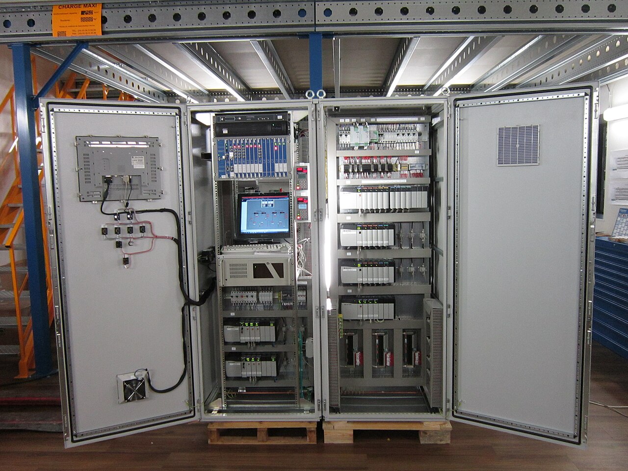
Industrial PLC cabinet shown as context only; it does not establish I/O topology, fuse/diode use, ratings, approvals, SENTOP origin, or a safe method. Photo: DWI / Wikimedia Commons, CC BY-SA 3.0; display-cropped and darkened.
Choose the circuit function before the terminal housing
“PLC I/O,” “24 VDC,” conductor size, and DIN-rail fit are not enough. Start with the intended current path and protection or conditioning objective, then prove the exact product configuration.
A holder plus a defined fuse link
Use it when the approved architecture needs a traceable fuse boundary. Confirm the fuse family, voltage, breaking or interrupting rating, time-current curve, pulse/inrush duty, dissipation, indication, and protected side.
A one-way semiconductor path
Use it only for the circuit role shown by the drawing. Confirm orientation, forward current, reverse voltage, forward drop, power, repetitive duty, thermal conditions, and open/short/leakage failure outcomes.
Blocking is not flyback suppression
A series blocking diode controls current direction. A flyback diode is normally a parallel load-suppression path for a DC coil. Their position, duty, timing effect, and evidence are different.
Neither part approves the complete circuit
The PLC manual, source, conductor, load, commons, jumpers, enclosure, assembly rules, protection study, and target-market evidence remain separate design inputs.
An external fuse may protect a branch conductor without protecting a semiconductor output under every fault. Internal electronic protection may protect a module without replacing required external branch or wiring protection. One PLC family even prohibits certain fused-interface arrangements in a stated sinking-output mode. The exact module manual controls.
Map the complete current and fault path
Sourcing and sinking describe the complete DC circuit, not a terminal-block property. Record the normal path, reverse path, shared common, group supply, field return, alternate source, diagnostic path, and possible backfeed before deciding where a fuse or diode belongs.
24 VDC source and distribution
Record normal/max voltage, source protection, available fault behavior, group feeds, redundant sources, and reference conductor.
Fuse, diode, or another interface
Define the actual function. A fuse, blocking diode, relay, disconnect, suppressor, or plain feed-through is selected for a different job.
PLC or remote I/O point
Confirm input/output type, channel and group limits, commons, diagnostics, internal protection, test pulses, and manual requirements.
Sensor, relay, lamp, valve, or actuator
Record operating/inrush current, polarity, inductive behavior, built-in suppression, release timing, abnormal states, and interface needs.
Common, return, and alternate paths
Map every shared conductor, bridge, common group, shield/PE distinction, remote supply, and path that can keep the circuit energized.
Conceptual architecture only—not a terminal diagram. Terminal numbers, conductor colors, polarity marks, common placement, fuse position, diode orientation, and suppression topology vary by exact module and approved drawing. For the wider marshalling context, see 24 VDC PLC I/O terminal blocks.
Device supplies current to the input
In a typical arrangement, a PNP field device supplies current to a sinking input whose common is at 0 V. Verify the exact manual; “PNP” does not identify a universal fuse location.
Device pulls current toward 0 V
In a typical arrangement, an NPN device needs a sourcing input whose common is at +24 V. A copied PNP branch layout can protect the wrong path or leave a shared common misunderstood.
Output switching method changes the review
A sourcing output switches positive potential; a sinking output switches the load return; a relay output has contact-duty limits. None makes a generic fuse or diode arrangement valid.
Opening one common or group fuse can disable several channels, while an alternate downstream source can backfeed a nominally open branch. Record channels per common, ON- and OFF-state current paths, diagnostic leakage, protected and unprotected conductors, and every alternate source. Do not assume one fused-interface arrangement works in both sourcing and sinking modes.
Define what the fuse must protect
A fuse terminal is a terminal assembly intended to receive a compatible fuse link. Its value is a visible, part-numbered protection boundary. It does not create correct coordination by itself. State whether the objective is conductor protection, a module-manual requirement, branch fault isolation, selective continuity, equipment protection, or another documented purpose.
Then select the link and holder together. Match AC/DC voltage, breaking or interrupting capability, time-current behavior, pulse/inrush duty, ambient derating, maximum sustained dissipation, and replacement control to the source and branch. Physical fit and an ampere marking are insufficient.
- Exact fuse family: 5 × 20 mm, 6.3 × 32 mm, blade, midget, and industrial fuse systems are not interchangeable because they fit a holder.
- Exact protected path: label protected and unprotected potential groups, source, field branch, module group, return, bridges, and diagnostic/test features.
- Exact thermal assembly: check holder current, fuse dissipation, indicator option, adjacent loading, ambient, spacers, and manufacturer installation data.
- Exact fault evidence: keep DC voltage, interruption, panel SCCR, protective-device coordination, and conductor protection in their own documented checks.

IEC 60947-7-3:2009 covers a defined class of industrial fuse terminal blocks receiving IEC 60127-2 cartridge fuse-links, within the standard's stated voltage, accessibility, and maximum short-circuit-breaking-capacity scope. It does not govern every fuse format, authorize a panel SCCR, or prove that a selected fuse protects a PLC point. Use IEC 60127-2 and IEC 60127-6 where their miniature fuse-link and holder scopes apply; IEC 60269-1 covers a different low-voltage high-breaking-capacity fuse framework.
Check the fuse link, holder, source, and branch together
Use one evidence row for every protected branch. Do not blend nominal current, holder rating, semiconductor protection, conductor ampacity, short-circuit interruption, and panel SCCR into one interchangeable number.
| Decision input | What to verify | Why the shortcut fails |
|---|---|---|
| Protection objective | State whether the fuse protects a conductor, required branch, field device, group supply, interface, or another defined element. | “Protect the PLC” is too vague. A fuse may open after an output transistor or relay contact is already outside its safe operating condition. |
| Fuse-link system | Exact family, dimensions, characteristic, current, AC/DC voltage, interrupting/breaking rating, pulse/inrush capability, approvals, and replacement part. | A same-size link can have a different voltage, curve, breaking capacity, temperature behavior, or approval. |
| PLC module | Exact point/group current, output type, manual-specified external protection, internal electronic behavior, diagnostics, commons, and prohibited arrangements. | Individual, group, interface-module, internal, and no-fuse architectures all exist. One diagram cannot be copied across modules. |
| Source and conductor | Source fault response, upstream device, conductor material/size/method, branch length, return path, and alternate/backfeed sources. | A 24 V label does not establish DC fault energy, interruption, or which conductor must be protected. |
| Holder and assembly | Maximum current/load, fuse dissipation, terminal temperature data, indicator circuit, spacers, bridges, enclosure ambient, and accessible replacement method. | The terminal's clamp rating neither sizes the fuse nor proves a fully loaded row will meet its thermal limits. |
| Release record | Schematic, terminal plan, protected/unprotected labels, fuse schedule, time-current evidence, approvals, test notes, spare-fuse control, and change history. | A replaceable part becomes an uncontrolled design change when only the ampere value is recorded. |
For the broader category decision, use the verified feed-through versus fuse terminal-block guide. For the separate assembly fault-duty question, see how panel builders verify panel SCCR.
Use the maximum prospective fault current to verify breaking or interrupting capability. Also use the minimum current available at a remote fault—after path impedance and power-supply current limiting or foldback—to verify clearing time from the full time-current curve. A switch-mode 24 VDC supply can remain in current limit or low voltage, so a traditional fuse or thermal-magnetic device may not clear in the assumed time.
Read the circuit symbol before the housing
A diode terminal contains one or more semiconductor paths. Direction is part of the ordered product, and the diode—not the conductor clamp—can be the limiting element. Review normal, reverse, turn-off, repetitive, fault, and thermal states before approving the part.

Start with the manufacturer's symbol and the intended current direction. Otherwise-similar terminal products can be ordered with opposite P-N or N-P orientations. Terminal level, side, numbering, or left-to-right appearance is not a safe polarity rule.
Then evaluate the diode as a real component: continuous and repetitive current, pulse or turn-off duty, reverse voltage, forward voltage, power loss, junction/assembly temperature, layout instructions, and failure behavior. A larger conductor does not raise the semiconductor rating.
Include open-circuit, short-circuit, reversed, and increased-leakage outcomes in the circuit review. Do not assume a diode always fails open, that a failed indicator remains obvious, or that PLC diagnostics will distinguish every failure mode.
Blocking or decoupling diode
A series diode permits current in its documented forward direction and blocks reverse current. It may support source decoupling, reverse-current control, or a specific logic/status path.
- Verify source sharing and every reverse path.
- Account for forward voltage at the downstream device.
- Check continuous/repetitive current and power.
- Do not assume diode OR-ing from a familiar symbol.
Flyback diode across a DC inductive load
A flyback or free-wheeling diode is normally a parallel path across a DC coil, reverse-biased during normal energization and conducting during turn-off. Its purpose and placement differ from a series diode terminal.
- Verify polarity, turn-off current, energy, repetition, and thermal path.
- Confirm the slower release-time effect is acceptable.
- Check for built-in coil suppression and PLC manual limits.
- Use an AC-appropriate suppressor for AC coils.
Component current under stated conditions
The diode path can be rated far below the terminal's conductor connection. Include steady, pulse, inrush, turn-off, and repetitive duty as applicable.
Worst documented blocking stress
Nominal 24 VDC is not the complete answer when inductive, shared-source, disconnection, or alternate-feed conditions exist.
Available voltage and heat
Forward voltage reduces the downstream margin and produces heat. Use product data at the relevant current and temperature.Planning relation: P ≈ VF × IF
Suppression is a dynamic duty
A standard series rectifier terminal is not automatically qualified for coil energy, high-speed switching, PWM, or repetitive clamp service.
Semiconductor plus terminal assembly
Check ambient, adjacent loading, spacer requirements, mounting, thermal derating, and the manufacturer's exact component configuration.
Open, short, leakage, or reversed
Document the effect on the load, PLC output, diagnostics, safe state, shared supply, and future testing. Do not treat one failure mode as universal.
For source OR-ing, review both-source and one-source-lost current, sharing, forward-drop headroom, thermal behavior, reverse leakage, source-to-source faults, upstream protection, diagnostics, and a shorted decoupling element. Use a purpose-built monitored redundancy module when the availability architecture requires it.
An LED is an electrical path—not decoration
An indicator can make a branch fault easier to locate, but it has a voltage range, internal topology, current path, power, and test behavior. An LED off-state is not proof of a healthy fuse or a de-energized circuit.
One product may publish a low-current indicator path for PLC/DCS use while another has a different range or topology. Use the exact SKU diagram and the exact input module's on/off thresholds, leakage limits, diagnostics, and common arrangement.
Choose the function—not a familiar part
These scenarios show the evidence path, not a field wiring arrangement, fuse value, diode direction, terminal order, or permission to modify a panel.
Several devices share a 24 VDC branch
Ask: Which branch needs selective protection, and what happens when one sensor shorts? Map source fault behavior, inrush, conductor path, input common, fuse curve, and protected-side label.
An output switches a solenoid or relay
Ask: Is suppression external, built into the load, or specified by the PLC? Verify DC/AC, output type, coil energy, diode polarity, placement, release timing, and repeated duty.
Two DC paths must be decoupled
Ask: What normal and reverse paths exist? Choose a diode symbol/orientation with verified voltage drop, current, reverse voltage, heat, source protection, and failure response.
A fuse LED sits near a sensitive input
Ask: Can indication current resemble an input state? Check the indicator circuit, voltage range, input threshold, common/reference, diagnostics, and open-fuse test condition.
PLC logic commands a larger device
Ask: Is an interface relay, solid-state interface, driver, or protected distribution module required? A fuse or diode terminal cannot raise the PLC point's load capability.
Turn the circuit role into a part-numbered terminal plan
A reviewable release connects the circuit, product, protection or semiconductor evidence, accessory system, labels, drawings, tests, and change record. It does not rely on a technician to reconstruct intent from a familiar terminal housing.
Freeze the exact equipment
Record PLC/remote-I/O module, manual and revision, source, field device, interface equipment, load data, and approved one-line or schematic.
Classify every circuit
Mark DI, DO, sensor supply, output supply, analog, high-speed, relay interface, diagnostic, safety-related, PE/shield, and special reverse-current or suppression need.
Map every path
Show source, branch boundary, protective device, terminal function, module point/group, load, return/common, bridges, and alternate/backfeed paths.
Choose the correct function
Select feed-through, distribution, fuse, diode, disconnect/test, relay interface, protection module, PE/shield, or another dedicated component for the stated job.
Verify fuse evidence
Record holder, link family, exact link, DC voltage, curve, interruption, inrush/pulse duty, dissipation, indication, protected side, and replacement control.
Verify diode evidence
Record symbol, direction, circuit role, forward/reverse ratings, loss, energy/repetition, temperature, spacing, diagnostics, and failure response.
Release the physical system
Approve exact terminal family, end plates, spacers, bridges, rails, markers, conductor data, strip order, enclosure conditions, approvals, and DIN-rail space.
Control tests and changes
Issue inspection/test notes, fuse and spare schedule, data-sheet revisions, open issues, substitution record, and handover. Field convenience changes return to review.
A fuse carrier or test feature is not safe isolation
Do not use a fuse carrier, removable link, test knife, PLC stop command, output-off state, or indicator as the sole means of de-energization. Utility or control power, redundant 24 VDC sources, UPS/battery circuits, field supplies, shared commons, load-side backfeed, and stored energy can remain.
Before exposed work, qualified personnel must identify every source, establish the correct isolation boundary, prevent reconnection, control stored energy, and verify the de-energized condition with appropriately rated test equipment under the applicable procedure. This page does not provide that procedure.

Request an exact circuit and terminal-strip review
Send enough evidence to identify the function, not only nominal voltage, current, and wire size. SENTOP can support model matching and BOM coordination; the project designer remains responsible for the complete PLC, protection, safety, and machine design.
Fuse and diode terminals in PLC I/O circuits
These answers define the selection boundary. Exact product manuals, drawings, circuit analysis, local requirements, and qualified personnel govern an installed circuit.
What is the difference between a fuse terminal block and a diode terminal block?
A fuse terminal holds a compatible fuse link to create a documented protection point. A diode terminal contains a semiconductor path that conducts in one documented direction and blocks in the other. They solve branch-protection and current-direction problems respectively; neither function can be selected from 24 VDC alone.
Can a fuse terminal block protect a PLC output?
It can be part of an approved output-branch design, but its presence does not prove protection of the output transistor, relay contact, conductor, or load under every fault. Modules use individual, group, interface, internal-electronic, combined, or no-fuse architectures. Follow the exact module manual.
Is a diode terminal block the same as a flyback diode?
No. Many diode terminals are series blocking or component terminals. A flyback diode is normally a parallel suppression path across a DC inductive load. The circuit location, current duty, polarity, turn-off behavior, and evidence are different.
Does every 24 VDC PLC branch use the same fuse convention?
No. Sourcing, sinking, relay, input, output, group-supply, field-supply, and shared-common arrangements differ. The protection objective, source, conductor, module manual, load, and fault path determine whether and where a fuse belongs.
Can I use a larger conductor with a lower-current diode terminal?
A larger conductor may fit the clamp, but it does not raise the diode's forward-current, reverse-voltage, pulse, power, or thermal limits. The lowest applicable semiconductor or assembly limit still governs that path.
Does a blown-fuse LED work with every PLC input circuit?
No. Indicator voltage range, topology, leakage/current path, power, common/reference, and the input module's thresholds and diagnostics are product-specific. Treat the LED circuit as an electrical component, not a passive label.
Should every DC inductive PLC load use a flyback diode?
Not as a blanket rule. The output module, load, built-in suppression, turn-off energy, repetitive duty, release-time requirement, and safety function determine the approved method. A simple diode can slow coil release; AC loads require an AC-appropriate suppressor.
Can I remove a fuse to isolate a PLC I/O circuit?
Do not assume that removal establishes an electrically safe condition. Alternate sources, shared commons, backfeed, control power, or stored energy can remain. Qualified personnel must follow the approved energy-control, lockout/tagout, and absence-of-voltage verification procedure.
What belongs on the terminal-strip drawing and BOM?
Record terminal tag and position, exact part number, circuit symbol and diode direction, fuse holder and selected link, protected/unprotected potential, PLC/field cross-reference, source and return, bridges, spacers, end parts, labels, manuals, approvals, and test or diagnostic notes.
Does internal PLC electronic protection eliminate external fuses?
Not necessarily. Internal module protection, external conductor or branch protection, selective fault isolation, and field-device protection can have different purposes. The exact PLC manual and documented protection architecture must assign those roles.
Standards and manufacturer evidence
Standards define scope and test frameworks; manufacturer documents define the exact module, fuse, holder, diode, terminal, indicator, accessory, and circuit conditions. Neither source type approves a complete panel by itself.
- IEC 60947-7-3:2009. Safety requirements for fuse terminal blocks. Defined IEC 60127-2 cartridge-fuse-terminal scope and test context.
- IEC 60127-2:2014+AMD1:2020. Cartridge fuse-links. Miniature fuse-link scope used by many control-circuit products.
- IEC 60127-6:2023. Fuse-holders for miniature fuse-links. Holder-specific scope; not a universal panel protection rule.
- IEC 60269-1:2024. Low-voltage fuses—general requirements. Separate high-breaking-capacity fuse framework.
- IEC 60947-7-1:2025. Terminal blocks for copper conductors. General support-mounted terminal-block scope.
- IEC 61131-2:2017. Programmable controllers and peripherals—equipment requirements and tests. PLC/PAC functional and EMC context; exact module data still govern.
- IEC 61010-2-201:2024. Safety requirements for control equipment. Control-equipment product safety context.
- UL 1059, Edition 6. Terminal Blocks. North American product-standard context; compliance does not by itself establish end-product suitability.
- OSHA 29 CFR 1910.333. Electrical safety-related work practices. U.S. de-energization, energy control, verification, and qualified-person boundary.
- Phoenix Contact. Fuse, component, and diode terminal blocks. Manufacturer overview showing protected/unprotected potential and blocking-diode functions.
- Littelfuse. Fuseology Selection Guide. Fuse voltage, breaking, time-current, pulse, temperature, and application-selection context.
- Siemens. S7-1200 G2 system manual. Model-family inductive-load suppression guidance and turn-off trade-offs.
- Rockwell Automation. ControlLogix digital I/O manual. Model-specific fusing, source/sink, interface, and output-protection evidence.
- Rockwell Automation. MicroLogix 1500 user manual. PNP/NPN and sinking/sourcing input context.
- Rockwell Automation. Topics in Circuit Protection for Power Supplies (Bulletin 1694). Distinguishes internal electronic protection from external branch and wiring objectives.
Make every fuse and diode function visible in the BOM
Send the exact PLC module, I/O schedule, source/load data, protection objective, diode symbol, terminal line-up, accessories, environment, quantity, target market, and documentation needs. SENTOP can review model matching and supply coordination without treating a terminal choice as complete PLC or machine approval.
