
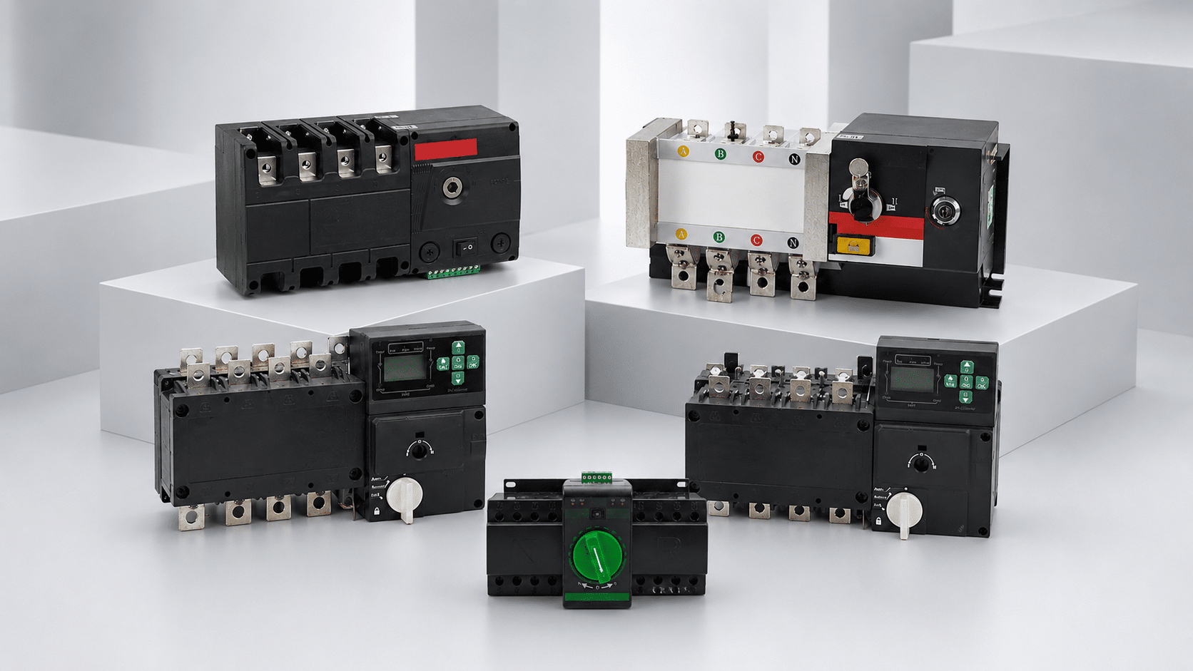
How an Automatic Transfer Switch Works: The 9-Stage Workflow
An automatic transfer switch does more than move contacts. It monitors power, confirms a real source problem, requests or verifies backup power, transfers only when the alternate source is acceptable, watches the connected load, qualifies the return of normal power, retransfers and resets the backup system.
The automatic transfer switch workflow follows validated conditions, not one fixed timer
In this article, “automatic switch” means an automatic transfer switch (ATS), also called automatic transfer switching equipment (ATSE) in IEC terminology. It is not a circuit breaker, relay, light sensor or generic automatic control switch.
In a normal utility-loss sequence, the controller monitors the preferred source. If that source remains unacceptable for the configured qualification period, the ATS may issue a generator-start request. It then waits until the alternate-source voltage and frequency meet the configured acceptance conditions, transfers the defined load, confirms the mechanism position and operates any provided load-priority logic.
When preferred power returns and stays acceptable for the configured retransfer period, the ATS moves the load back. A generator may then run unloaded for its manufacturer-defined cooldown or stop delay. Approved exercise, remote, manual or go-to-source commands can start a different sequence even while normal power is available.
If a source changes during a timer, the controller may cancel, restart or bypass that delay. If a commanded position is not reached, it may alarm, inhibit, retry or follow a documented failsafe path. Never copy another model’s response or timer values.
Nine stages from normal power to standby again
This is the common utility-generator path. A dual-utility or battery system keeps the same decision pattern but replaces the generator-start and cooldown steps with its own source logic.
Monitor the preferred source
The load remains on normal power while the controller watches the electrical conditions supported by that model.
Gate: normal source is acceptable and the switch position agrees.Qualify the abnormal condition
A configured delay can reject a short dip or disturbance before it becomes a generator start or transfer event.
Gate: normal remains outside its acceptance limits.Initiate the alternate source
The ATS may close a remote-start contact or send the approved command. The generator controller manages cranking, speed and protection.
Gate: the applicable command is accepted by the source system.Qualify alternate power
The ATS separately checks that backup voltage and frequency, plus any provided phase conditions, are acceptable.
Gate: source-ready logic is satisfied for the required time.Transfer the defined load
The mechanism operates as open, delayed open, open in-phase or closed transition under the exact design conditions.
Gate: source, interlock and transition permissives allow movement.Confirm position and manage load
Position feedback, alarms and any provided load shed, priority or step-loading logic show whether the intended state was achieved.
Gate: connected demand matches the source and load plan.Qualify restored normal power
The ATS keeps monitoring normal power and normally waits for it to remain acceptable before returning the load.
Gate: restoration survives the configured retransfer period.Retransfer to normal
The load moves back by the selected transition method. A documented failsafe may bypass delay if the alternate source fails.
Gate: normal is acceptable and retransfer is not inhibited.Cooldown and return to standby
A generator may run unloaded for its defined stop delay before the start request is removed and the system resets.
Gate: source/controller states and alarms return as designed.The ATS controls the transfer, but other equipment completes the system
Confusing these roles leads to poor diagnosis and incomplete quotations. The controller can request and supervise a change without producing energy or clearing every fault.
Source selection
Monitors supported source conditions, applies the configured logic and operates the transfer mechanism.
The transfer function does not generate power or replace required overcurrent protection. Some listed assemblies integrate separately rated OCPDs.Engine and generator control
Governs cranking, speed, excitation, protection, alarms and shutdown after receiving the approved request.
The ATS still makes its own alternate-source acceptance decision.Fault and overload protection
Breakers, fuses, conductors and the assembly must coordinate with fault current from every source.
The ATS ampere rating does not establish short-circuit suitability.Priority and capacity
Associated controls can shed, delay or restore optional loads so the alternate source is not overcommitted.
These functions exist only when specified, integrated and commissioned.WCR checkpoint: withstand-and-closing rating (WCR) is not an interrupting rating. For each source that can energize the ATS, compare available fault current with the exact marked WCR and its permitted upstream fuse, breaker or clearing-time condition. Review the separate ATS buying guide before releasing a model.

“Generator running” is not the same as “alternate source acceptable”
The ATS begins with sensing. Depending on the controller, this may include undervoltage, overvoltage, underfrequency, overfrequency, phase loss, imbalance or phase rotation. Do not assume every ATS monitors every condition.
In the normal outage path, a loss-qualification delay can keep a momentary event from becoming a generator cycle. When the condition persists, the ATS sends the configured start request. A common interface is a two-wire dry contact, but it is not universal. Control voltage, contact rating, source-ready signals and accessory modules must match the exact generator.
- If normal returns during qualification: the controller may cancel the countdown and remain on normal power.
- If the generator starts: the ATS still waits for its own supported voltage/frequency acceptance logic and any configured stabilization delay.
- If the alternate never qualifies: the ATS should follow its documented alarm, hold, inhibit or fallback response instead of transferring blindly.
- If a test command starts the cycle: normal power may still be available, so the sequence can differ from a real outage.
Transition mode changes the middle of the workflow
Open, delayed open, open in-phase and closed transition solve different load problems. They do not create power or remove the need to qualify both sources.
Break before make
The connected source opens before the alternate closes. The load sees an interruption, and the sources are not intentionally paralleled.
Common where a brief gap is acceptable and source overlap is not allowed.Center-off interval
The switch holds the load disconnected for a defined time so selected motors, transformers or residual voltage can decay.
The delay belongs to the load study and exact equipment—not a generic setting.Still break before make
The controller waits for a favorable phase relationship before reconnecting. The sources are not paralleled, and the load still sees a gap.
If matching is not achieved, the documented fallback may use delayed/open transfer.Make before break
Two live, acceptable and synchronized sources overlap briefly so a planned transfer or retransfer may avoid a load interruption.
Specify synchronization, protection, parallel time, failure response and utility approval.What each ATS delay is trying to prevent or prove
Names differ by controller. Some models expose every timer; others fix, combine or omit them. Use the approved sequence, exact manual and commissioning record rather than copying values from another site.
| Logic or delay | Question it answers | If the condition changes | Evidence to retain |
|---|---|---|---|
| Normal-source sensing | What voltage, frequency, phase or other condition counts as unavailable? | The controller continues monitoring; unsupported or disabled functions must not be assumed. | Exact thresholds, hysteresis, sensing phases and controller configuration. |
| Loss/start qualification | Has the normal-source problem lasted long enough to start backup action? | If normal becomes acceptable first, the countdown may abort and the system may remain on normal. | Timer value, event trigger, cancel behavior and load interruption objective. |
| Alternate acceptance | Is backup voltage and frequency stable enough for the defined load? | If the source drops out of range, the delay may restart or the controller may alarm/hold. | Acceptance window, stabilization logic, phase sequence and source-ready interface. |
| Transfer / step load | Should the load connect immediately or in a managed sequence? | Source or permissive loss can block transfer; load logic may keep optional demand shed. | Priority schedule, starting duty, delays, shed/restoration contacts and test result. |
| Retransfer qualification | Has preferred power returned and remained acceptable? | If normal drops out, the timer normally resets. If alternate fails, a documented failsafe may bypass it. | Return threshold, delay, manual/non-return mode and alternate-failure behavior. |
| Cooldown / stop delay | Should the generator run unloaded after the load returns to normal? | An alarm, emergency stop or source-specific condition can alter the stop sequence. | Generator manufacturer requirement, ATS command behavior and measured test record. |
Do not optimize every timer for minimum duration. A shorter delay can reduce outage time but can also increase nuisance starts, unstable load pickup or rapid source cycling. The correct setting balances the load’s continuity need with source behavior and the approved design.
The workflow changes when the alternate source changes
Do not reuse a generator narrative for a dual-utility, battery, solar or multiple-generator design. The source interface and restoration rules can be materially different.
Start, qualify, load, cool
The ATS commonly requests engine start, qualifies generated power and transfers the planned demand. After retransfer, the generator may cool down.
Verify: start interface, source acceptance, step load, fuel/controller alarms and cooldown.Two sources may already be live
No engine-start stage may exist. Source independence, priority, metering, protection and transition permissions become central.
Verify: utility agreements, source relationship, parallel prohibition/approval and return mode.Backup gateway and islanding
The system may manage grid separation, grid-forming output, metering, charging, state of charge, solar and power-control limits.
Use only a manufacturer-approved architecture; a generic generator ATS is not proof of compatibility.Priority and redundancy logic
Runtime balancing, source priority, multiple ATS step loading, parallel controls and failover layers may be added.
Require an engineered system sequence and end-to-end acceptance test.Standard-scope boundary: multi-source, load-shedding, hybrid and energy-storage arrangements are system-level designs. Confirm the standard and certification for the complete assembly; do not assume that a two-source ATSE standard covers every added control function. Static transfer switches follow a separate standards path.
Observe the workflow state before anyone opens the equipment
Owners and facility teams can collect useful information from safe, intended user interfaces: source indicators, mechanism position, controller alarms, generator display, event history, time of event and which loads were connected. These observations help a qualified service team find the stage that did not complete.
- Normal fails, generator does not start: note ATS mode, visible alarms and generator controller status. Do not jump start terminals or bypass controls.
- Generator runs, load does not transfer: the alternate source may not meet ATS acceptance conditions, or a permissive, timer, interlock or mechanism state may block movement.
- Transfer occurs, major loads drop out: compare the event with the approved load study, starting duty and load-management sequence.
- System cycles between sources: record timing and power-quality evidence; do not change retransfer thresholds without design review.
- Generator continues after retransfer: compare elapsed time and alarms with the model-specific cooldown/stop sequence.

Prove the complete chain, then keep a settings baseline
A generator exercise without load does not prove that the ATS can transfer, that the intended loads will operate or that alarms and failure paths work. Use the exact manufacturer procedure and the project’s approved test plan.
Approve the documents
Reconcile the one-line, exact ATS/controller, source manuals, load schedule, neutral/grounding design, protection data and sequence of operation.
Output: approved submittal and test script.Inspect the as-built system
Qualified personnel confirm labels, enclosure, conductors, interfaces, accessories, source/load identity and settings against the approved design.
Output: corrected punch list before functional test.Run controlled functional tests
Verify source sensing, start/ready logic, transfer and retransfer, planned load pickup, shedding, alarms, communications, failure states and cooldown.
Output: measured times, states and results—not assumptions.Handover and maintain
Record final settings, as-built drawings, model/serial data, event-log baseline, owner instructions, service contacts and the approved maintenance plan.
Output: a repeatable future troubleshooting reference.
Give every bidder the same ATS workflow
A phrase such as “automatic generator transfer” does not define source thresholds, load priorities, return behavior or fault responses. Send a written sequence and require each proposal to identify the exact supported functions, assumptions and documents.
SENTOP can review product families, order codes, supplied options, project BOMs, technical documents, OEM packaging and bulk quotation. The project designer, source manufacturer, utility, installer, commissioning team and authority having jurisdiction remain responsible for the complete system design and approval.
Automatic transfer switch workflow FAQ
These answers explain normal behavior. Exact timing, control inputs and failure response still come from the ordered ATS, source equipment and approved sequence.
What does an ATS do during a power outage?
It monitors the preferred source, qualifies the abnormal condition, requests or verifies alternate power, waits until that source is acceptable and transfers the defined load. It then monitors the connected source and, where the design provides, the alternate source, manages any specified priority logic and later retransfers when the preferred source has returned under the approved conditions.
Why does an ATS wait before starting the generator?
A loss-qualification delay can distinguish a lasting outage from a short voltage dip or switching disturbance. If normal power recovers before the delay ends, the controller may cancel the sequence. The correct delay is model- and project-specific; some approved test or remote commands can start the generator while normal power is still available.
Why does the generator start but the ATS not transfer?
The engine-running state does not prove that the alternate source meets the ATS voltage, frequency and other configured acceptance conditions. A timer, permissive, interlock, load-control input, wrong operating mode, source fault or mechanism alarm may also block the move. Record visible alarms and have qualified service personnel follow the exact diagnostic procedure.
What is retransfer delay?
Retransfer delay is the period used to confirm that restored preferred power remains acceptable before the load returns. It helps avoid rapid cycling during an unstable restoration. A documented failsafe may bypass the delay if the alternate source fails, and some systems use manual or non-return logic instead of automatic retransfer.
Why does the generator keep running after utility power returns?
The ATS normally waits for stable preferred power, retransfers the load and may then keep the generator running unloaded for a manufacturer-defined cooldown or stop delay. Compare the actual time and any alarms with the equipment documentation; do not change controls because another generator uses a different value.
Does closed-transition ATS mean uninterrupted backup power?
No. Closed transition can avoid a transfer gap only when both sources are live, acceptable and synchronized. If the connected utility has already failed, it cannot overlap with that source, so the load sees an interruption while backup starts and qualifies unless a separate UPS or energy-storage ride-through system is provided.
Is an ATS the same as a circuit breaker?
No. An ATS selects which source supplies a load; a circuit breaker or fuse provides overcurrent protection under its rated conditions. Some listed transfer-switch assemblies integrate breakers or other OCPDs, but the transfer and protective functions remain separately rated and coordinated.
Can a battery system use the same workflow as a generator ATS?
The high-level decision path is similar, but the implementation is not interchangeable. Battery and solar systems can add grid-forming, anti-islanding, metering, charging, state-of-charge, backup fault current, firmware and utility power-control requirements. Use a manufacturer-approved backup architecture and commissioning process.
Verify the sequence with current source documents
These sources explain standard scope and common logic. The exact ordered model’s certificate, nameplate, controller manual, source manual and approved project sequence remain the controlling evidence.
