
Which system and authority?
Define optional standby, emergency, legally required, residential, commercial, or multi-source use. Record the AHJ, utility, adopted code, and project standard.
A safe automatic transfer switch installation is a permitted, designed, and commissioned source-transfer project—not a remote DIY wiring job. Match the exact ATS to both sources, the selected loads, system voltage and phase, fault duty, neutral and grounding design, enclosure, controls, and local approval path before field work begins.
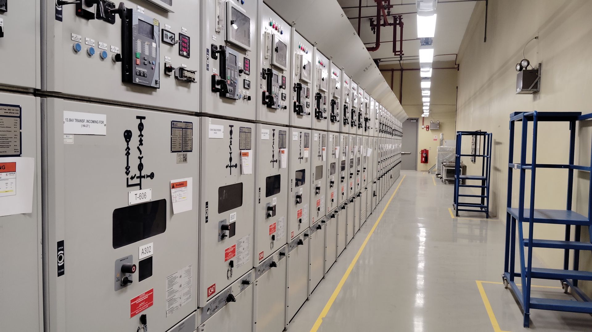
Industrial electrical control room with rows of switchgear. The scene illustrates the wider power-distribution environment; it does not identify an ATS model or rating. Photo: Shameer Vayalakkad Hydrose / Pexels, used under the Pexels License; darkened and cropped for this hero.
If any gate is unresolved, the project is not ready for purchase or installation. A large ampere label cannot close the gaps.
Define optional standby, emergency, legally required, residential, commercial, or multi-source use. Record the AHJ, utility, adopted code, and project standard.
Document utility, generator, inverter, battery, PV, UPS, service arrangement, priority circuits, running demand, starting demand, and load management.
Verify voltage, phase, frequency, poles, ampere rating, transition, service role, WCR/protection, enclosure, controls, and listing for the intended use.
Assign one-line ownership, permits, utility coordination, outage and isolation, qualified installation, inspection, commissioning, owner training, and records.
An automatic transfer switch (ATS) selects a defined load between a normal source and an alternate source according to its evaluated construction and control logic. In a typical standby-generator project, utility power is normal and the generator is alternate. The exact switch may sense source quality, issue a start signal, wait for the alternate source to qualify, transfer the load, and later retransfer after normal power is stable.
Those actions are model-specific. A safe project starts with a site survey and an approved one-line diagram. The qualified team then matches equipment, plans a controlled outage, isolates every possible source, installs to the exact instructions, completes inspection, and commissions the whole system. This page explains what that process must contain. It does not show terminal locations, conductor landing, bonding changes, or live test steps.
The ATS is one device inside a wider system. A drawing must show how the normal source, alternate source, transfer equipment, protection, distribution, loads, neutral, grounding, and controls relate.
Record nominal voltage, phase, service/disconnect arrangement, available fault current, equipment condition, and sensing point.
Record source ratings, neutral/bonding configuration, controller, starting or surge capability, fuel/runtime, and source qualification.
Match poles, neutral, transition, ampere and WCR data, service role, enclosure, upstream OCPD, controls, accessories, and listing conditions.
Identify priority circuits, running and starting demand, load shed or sequencing, downstream protection, labels, and owner expectations.
The service strategy controls the load path, equipment role, conductor arrangement, controls, and commissioning plan. “Whole home” is not automatically safer or better.
| Architecture | Good fit | Resolve before purchase | Main limitation |
|---|---|---|---|
| Whole-service transfer | The backup source, service equipment, ATS, and load-management plan are designed for broad coverage. | Service-equipment status, system rating, available fault current, neutral/bonding, utility/AHJ review, large-load strategy, and source capacity. | An ATS matching the service amperes does not prove the generator can carry all simultaneous loads. |
| Essential-load panel | Only defined priority circuits need backup during an outage. | Exact circuit inventory, feeder/protection, motor starting demand, spare capacity, circuit directory, and owner priorities. | Important loads may be omitted if the survey and owner interview are weak. |
| Managed-load system | Large loads need priority, delay, lockout, sequencing, or shedding because backup capacity is limited. | Compatible controllers/contactors, priority rules, restart behavior, fail-state behavior, and proof testing. | More control flexibility creates more integration and documentation work. |
| Solar + storage + generator | The site needs resilience from several sources or islanding modes. | Listed system architecture, source precedence, inverter and generator controls, utility interconnection, neutral/grounding, and one commissioning owner. | A standalone ATS added later can conflict with islanding logic or create an undocumented source path. |
The ATS rating and the backup-source capacity are different decisions. Size and manage loads from the real operating plan, including starting demand, seasonal operation, and what must remain off during backup.
All can be valid only in an approved design. None authorizes receptacle backfeeding or makes an arbitrary panel arrangement acceptable.
Emergency, legally required standby, fire-pump, healthcare, and other regulated systems may require different equipment, automatic operation, segregation, testing, and documentation. Do not apply a residential optional-standby shortcut to them.
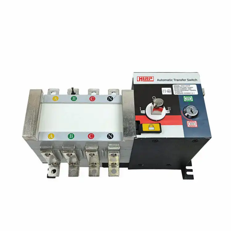
Do not buy an ATS from voltage and amperes alone. Available fault current at the installation point and the transfer switch's short-circuit withstand/closing rating (WCR), including any required upstream protective device, can decide whether a product is suitable. Service-equipment use, neutral switching, enclosure entries, control power, generator start contacts, and accessories also change the approved configuration.
UL 1008 covers several transfer-switch categories, including automatic, manual, closed-transition, bypass/isolation, service-equipment, and some inlet arrangements within its scope. A standard name or logo does not cover every product from a supplier. Verify the exact catalog number, rating, certification status, markings, instructions, and conditions.
A similarly sized substitute is not equivalent until the designer confirms the full electrical, mechanical, environmental, control, certification, and documentation match.
Match both sources and the load system. Record sensing points, control power, conductor configuration, and phase rotation where applicable.
Use the calculated served load and equipment rules. ATS amperes do not establish generator capacity or prove every load can run together.
Verify available fault current, marked/protected rating, exact protective-device relationship, conductor conditions, and downstream assembly rating.
Choose transition for the actual load and source conditions. Closed transition can intentionally parallel sources and requires specialized coordination.
Base pole count and neutral treatment on the separately-derived-source analysis, ground-fault scheme, one-line, product listing, and AHJ decision.
Confirm where the device sits, service-equipment suitability, disconnect and bonding arrangement, utility requirements, and working space.
Verify indoor/outdoor use, water, sunlight, corrosion, temperature, physical protection, mounting, glands/conduit, clearances, and access.
Confirm controller compatibility, dry contacts or communications, timing, exercise, priority logic, fail states, remote monitoring, and settings ownership.
Each phase has a clear output. The qualified installer still follows the exact manual, approved drawing, site safety procedure, and local rules.
Inspect service and distribution equipment, sources, loads, site, environment, fuel/ventilation, existing defects, physical space, and approval needs.
Output: site record, load inventory, scope boundaries, and responsible parties.Map normal, alternate, transfer, service/disconnect, neutral, grounding, protection, managed loads, solar/storage, and every possible backfeed path.
Output: approved one-line, source statement, and load strategy.Review ATS, generator/inverter, controller, upstream OCPD, enclosure, conductors, accessories, labels, settings, certification, and documentation.
Output: controlled equipment schedule and submittal package.Coordinate the AHJ/utility where required, owner communications, shutdown, all energy sources, lockout/tagout as applicable, voltage verification, safeguards, and restoration.
Output: approved outage/isolation plan—not “turn off the main.”Qualified personnel mount, route, terminate, bond, label, and configure only as the equipment instructions and approved drawings require. No generic torque or wiring diagram applies.
Output: inspected installation, labels, updated drawings, and settings record.Prove the automatic sequence, intended loads, management logic, alarms, abnormal behavior, retransfer, and owner controls under the manufacturer procedure.
Output: signed test log, as-built package, training, maintenance plan, and open-items closure.
Utility, generator, battery, photovoltaic, inverter, UPS, control power, stored energy, and induced or unrelated backfeed can affect the work area. The qualified team identifies every source before shutdown. If transfer equipment is at the service entrance, opening its service disconnect does not prove line-side parts are de-energized; utility isolation may be required. Where OSHA general-industry rules apply, exposed work normally starts with de-energization, lockout/tagout, control of stored energy, and verification by a qualified person using suitable test equipment.
Personal protective equipment does not turn an unjustified energized task into a safe DIY task. A noncontact tester alone does not replace the required absence-of-voltage procedure. The site electrical-safety program, equipment documentation, and applicable workplace or construction rules define the work method.
Portable generators add carbon-monoxide and fuel hazards. Follow CPSC and manufacturer guidance for outdoor placement, exhaust direction, alarms, weather, fuel, refueling, and clearances. The ATS does not manage those hazards.
Whether an alternate source is separately derived affects neutral switching, source bonding, ground-fault behavior, and pole count. Some systems use a solid neutral. Others switch the neutral through listed transfer equipment. The correct choice follows the exact source configuration, ATS design, protective scheme, one-line, and AHJ determination.
Do not remove or add a bonding jumper, install a grounding electrode, or re-land a neutral because another project looks similar. A wrong change can create objectionable current paths, prevent fault clearing, disturb ground-fault protection, or energize exposed metal.
The answer belongs to this exact configuration—not to the generator brand or a generic diagram.
Verify the precise catalog number, internal construction, pole count, markings, and listing conditions.
Document the service, source, transfer, grounding-electrode, and fault-current path on the approved one-line.
Include solar, storage, UPS, generator, utility, bypass, and control supplies—not only the two ATS power terminals.
Transfer-switch amperes describe the device within stated conditions. They do not prove the generator, inverter, battery, conductors, or fuel system can support every connected load at once.
Identify loads tied to life safety, safe shutdown, fire protection, freezing, flooding, ventilation, medical needs, or other site-specific hazards.
Design action: define the governing rule, required restoration time, autonomy, and failure response.Prioritize controls, communications, refrigeration, pumps, selected process equipment, security, and other loads needed for the facility's core function.
Design action: record starting current, sequence, duty cycle, and what may be shed.Large heating, cooling, cooking, charging, and noncritical process loads may need delay, lockout, staged return, or owner choice.
Design action: do not let an attractive whole-building label replace a measured load strategy.A useful load schedule separates running load from starting or transient demand. It also shows which loads can overlap, which must be delayed, and which can be dropped when source capacity falls.
For a structured starting point, use SENTOP's transfer switch selection guide. Final sizing still belongs to the approved project design and exact equipment documentation.
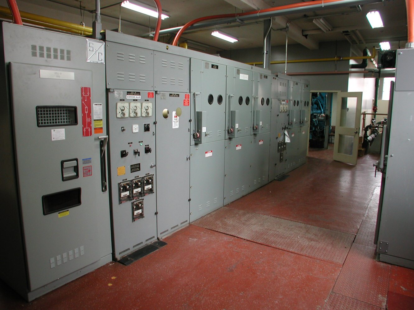
A successful startup proves the approved sequence and leaves a record another qualified person can understand. The test plan should come from the project requirements and exact manufacturer instructions.
Testing must not create an uncontrolled interruption, backfeed path, unsafe generator condition, or unexpected start. Coordinate affected people and systems before any functional test.
Confirm approved one-line, equipment schedule, exact catalog numbers, settings, conductor and terminal records, labels, permits, inspection status, and open items.
Confirm voltage, frequency, phase sequence where applicable, neutral arrangement, source labels, load priorities, isolation points, controller inputs, and emergency contacts.
Record source-failure recognition, start command, source qualification, transition, interruption time, transferred loads, alarms, and any load-shed or staging action.
Verify source stability and priority behavior at an approved load condition. Record current, voltage, frequency, abnormal indications, and the loads that were intentionally excluded.
Check normal-source qualification, retransfer delay, cool-down or shutdown sequence where applicable, return of managed loads, controller reset, and expected fail states.
Provide signed results, settings, as-built drawings, manuals, certificates, spare-parts information, training, maintenance ownership, test intervals, and unresolved-item closure.
Voltage, phase, frequency, poles, transition, WCR, enclosure, service role, controller, neutral, and certification can make a same-amp device unsuitable.
The ATS may be large enough while the alternate source is not. Build a load schedule and define priority, starting, staging, and shedding.
Neutral treatment follows the actual source and grounding design. A generic three-pole or four-pole rule can create dangerous current paths.
Male-to-male cords, defeated interlocks, and unapproved backfeed arrangements can energize utility conductors or exposed contacts. Use evaluated transfer equipment and an approved design.
Solar, storage, UPS, bypass, control power, and multiple generators belong on the one-line. A two-source assumption may leave a live path behind.
The enclosure, hubs, conduit entries, glands, drains, mounting, sunlight, water path, corrosion, working space, and cable support must remain within the evaluated system.
Use the exact model's controlled instructions and approved drawings. Never borrow torque, strip length, conductor count, fuse, timing, or control values from a similar device.
A green display does not prove transfer, managed loads, alarms, neutral behavior, or restoration. Test, document, train, and assign maintenance responsibility.
A standard title is not a product certificate, a permit, or a complete installation design. Verify the adopted edition, exact device record, project category, and authority requirements.
UL 1008 covers defined transfer-switch equipment within its scope. Confirm the exact model, ratings, transfer type, WCR conditions, service-equipment suitability if required, and current certification record. Do not extend a family logo to an unverified catalog number.
View the official UL 1008 pageEmergency, legally required standby, and optional standby systems are not interchangeable labels. The adopted edition, system classification, service arrangement, wiring methods, protection, grounding, and AHJ interpretation determine the project rules.
Access NFPA 70 informationWhere the project falls within its scope, the design team uses the applicable performance class, type, level, installation, operation, and maintenance provisions. Buying a listed ATS does not by itself establish NFPA 110 compliance.
Access NFPA 110:2025Where OSHA general-industry rules apply, qualified personnel, de-energization, lockout/tagout, stored-energy control, and verification requirements govern the work. Residential legal duties may differ, but the hazard does not disappear.
Read OSHA 1910.333Good model matching starts with the sources, loads, installation role, transition, neutral, fault duty, environment, control sequence, approvals, and delivery scope. SENTOP can review the commercial product requirement; the project designer and AHJ retain installation authority.
Review the SENTOP ATS category before requesting exact-model matching.
Explore automatic transfer switchesCompare a human-operated transfer path where automatic restoration is not required.
Explore manual transfer switchesFrame source, load, controls, and transfer equipment as one standby-power solution.
Review the generator transfer solutionSee how backup-power projects connect equipment choices to system requirements.
See generator and standby applicationsCompare system voltage, load, transition, poles, fault duty, enclosure, and controls.
Open the selection guideUse this page for wiring architecture and document inputs—not as permission for live work.
Open the wiring guideReview available company and product evidence, then verify the exact model and scope.
Review standards and certificatesShare a controlled RFQ for product matching, OEM needs, samples, and documentation.
Review ATS manufacturing supportThe answers below define the project boundary. The approved design, exact instructions, utility rules, adopted code, and AHJ still control the installation.
An ATS connects independent power sources and can expose workers, occupants, equipment, and utility personnel to backfeed, fault, arc, and carbon-monoxide hazards. Use a qualified designer and installer, obtain required utility or permit approvals, and commission the completed system. This article does not provide a DIY wiring procedure.
A correctly selected, evaluated, installed, and functioning transfer system is intended to isolate sources in its approved operating configuration. That protection depends on the exact topology, product, wiring, interlocks, controls, maintenance, and test results. Improvised cords or defeated interlocks bypass the safety concept.
An ATS senses source conditions and performs an automatic sequence through its controller. A manual transfer switch requires an operator. Either can provide an approved transfer function when it matches the system; the choice depends on restoration time, staffing, criticality, source controls, maintenance, and governing rules.
Choose from a load study, source capability, outage goals, space, budget, and code category. Whole-building transfer can simplify the load side but may require load management. An essential-load panel creates a clear boundary but requires careful circuit selection and documentation.
There is no universal answer. Neutral switching depends on whether the alternate source is separately derived in the actual design, plus bonding, ground-fault protection, source configuration, ATS construction, the approved one-line, and AHJ requirements. Do not select pole count from a generic diagram.
It can be part of a coordinated multi-source system, but solar, storage, inverter, generator, utility, export control, islanding, bypass, and control logic must all appear on the approved one-line. Equipment ratings and control sequences must be mutually compatible; a standard two-source diagram is not enough.
At minimum, confirm documents and labels, source identity and quality, normal-to-alternate transfer, intended-load behavior, load management, alarms, abnormal states, retransfer, source shutdown, settings, as-built records, training, and unresolved items. Follow the manufacturer and project test procedure.
Only through equipment and an inlet arrangement evaluated and approved for that source and installation. Never use a male-to-male cord or backfeed a receptacle. Follow generator instructions and CPSC guidance for outdoor placement, exhaust, carbon-monoxide alarms, weather, fuel, and refueling.
These sources establish scope and safety principles. They do not replace the locally adopted requirements, exact product instructions, or project approval.
Send both source ratings, load and starting profile, system architecture, neutral decision, available fault current, transition, enclosure, controls, certification target, quantity, and timeline. SENTOP can support product matching without replacing the project's qualified design and approval process.
