Cold-pressed terminal blocks make it easy and safe to join wires. You can use them to connect wires to other wires or to a board. These connector accessories help you avoid many common problems:
- They make the connection safer and more reliable.
- They stop too much heat from building up.
- They help you save time and money.
| Year Range | Market Growth Trend |
|---|---|
| 2018-2024 | Steady Increase |
| 2025-2030 | Continued Growth |
You should check the size, material, and contact strength for the best results.
Key Takeaways
- Cold-pressed terminal blocks join wires safely. They do not need heat or solder. This makes setting them up fast and simple. These blocks help keep things safe and reliable. They stop wires from getting too hot. They also make sure the wires stay tightly connected. Pick the right terminal block for your project. Screw clamps hold wires tightly. Push-in types are easy to use. Check the blocks often to keep them working well. This stops rust and loose wires. Always use the right size block for your wire. Match the block to your wire thickness and current. This keeps the connection strong and safe.
Cold-Pressed Terminal Blocks Overview
What They Are
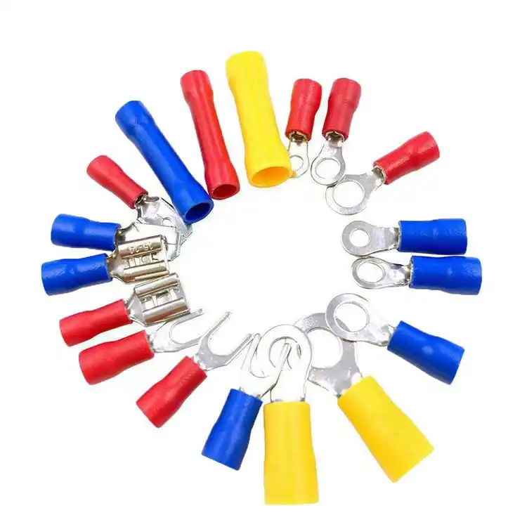
Cold-pressed terminal blocks help you connect wires fast and safely. These blocks work as connector accessories in electrical systems. You can join wires to other wires or to a board. You do not need heat or solder for this. This makes them different from cold-pressed terminals. Cold-pressed terminals are single connectors on the end of a wire. Cold-pressed terminal blocks hold many wires together in one spot. This helps keep your electrical work neat and safe.
The main parts often have copper tinned U-shaped terminals. Copper lets electricity flow well. Tin coating stops rust from forming. The U-shape gives more contact area. This means less resistance and better energy flow. You get a strong and safe connection for your system.
Tip: Pick terminal blocks with good copper and a strong U-shaped design for top results.
How They Work
You can put in cold-pressed terminal blocks without special tools or heat. The steps are easy and quick. First, put the wire into the block. Next, tighten the terminal head to hold the wire. Some blocks use piercing to connect wires without removing insulation. Others use riveting or plug-in ways. These designs grip wires tightly and stop them from coming loose, even if things shake.
- You do not need to weld or solder.
- The connection stays tight and does not pull out easily.
- The setup saves time and lowers mistakes.
Tinned copper and the U-shape keep the connection steady. You lose less power and your system stays safe.
Common Uses
Cold-pressed terminal blocks are used in many places. They work in factories, stores, and homes. Here is a table that shows some common uses:
| Sector | Application Description |
|---|---|
| Industrial | You can make work faster, help production lines, and support modular designs. |
| Commercial | You get strong wire-to-wire and wire-to-board connections for quick setups. |
| Residential | You save time and stay safe by not using heat, so they are good for home electrical jobs. |
You see these blocks in control panels, distribution boxes, and renewable energy systems. They help you make safe, quick, and lasting connections for many electrical projects.
Features and Types
Key Characteristics
Cold-pressed terminal blocks have special features. You do not need heat or soldering. This helps you avoid problems like oxidation and cracking. Makers use extrusion technology to make them strong. These blocks are more reliable than older types. They give better mechanical strength and electrical flow. You can install them fast, even in hard places.
- No melting of metal
- Strong connection without welding
- Easy installation
- Good performance in tough conditions
Note: Cold-pressed terminal blocks are also called crimped terminals. You use them for power connections. They hold wires tightly and safely.
Materials Used
The materials in cold-pressed terminal blocks are important. They help with safety and how well the blocks work. You find plastics like polyethylene, polypropylene, and polyamide. These plastics fight moisture, heat, and fire. The metal parts use copper and aluminum. These metals help electricity move. Tin and gold plating stop rust and make the blocks last longer.
| Material | Advantages | Applications |
|---|---|---|
| Polyethylene (PE) | Low cost, good moisture resistance | Low-voltage terminal blocks |
| Polypropylene (PP) | Higher heat resistance, better mechanical strength | Industrial and automotive terminal blocks |
| Polyamide (PA/Nylon) | Excellent flame retardancy, high-temperature resistance | Fire-safety-critical applications |
| Copper (Cu) | High conductivity, easy to machine | Internal conductive parts |
| Aluminum (Al) | Lightweight, cost-effective | Internal conductive parts |
| Tin (Sn) Plating | Prevents oxidation, improves solderability | Coating for conductive parts |
| Gold (Au) Plating | Used in high-reliability applications | Coating for high-reliability applications |
When you pick materials, think about insulation and safety. The right plastic keeps wires apart. It stops short circuits. Good metals lower resistance. They help your system work well.
Main Types
You can choose from different cold-pressed terminal blocks. Some blocks use screw clamps for a tight grip. Others use spring clamps for quick connections. Push-in types let you connect wires without tools. New designs have sensors and smart modules for checks. Thin-profile blocks save space. Heavy-duty blocks handle high currents.
- Screw clamp blocks for strong, secure connections
- Spring clamp blocks for fast, tool-free wiring
- Push-in blocks for easy installation
- Smart blocks with sensors for monitoring
- Modular blocks for flexible setups
- Heavy-duty blocks for large currents
🛠️ Tip: Pick the type that fits your project. For high safety, choose blocks with good insulation and smart features.
Advantages and Drawbacks
Safety and Reliability
Cold-pressed terminal blocks give you good safety. They are reliable for many jobs. These blocks meet rules from around the world. You can look for certifications like CE, UL, RoHS, VDE, ISO 9001, TUV, and CCC. These marks show the blocks are safe and high quality.
| Certification | Description |
|---|---|
| CE | Follows EU rules and helps sell in Europe. |
| UL | Meets North American safety standards. |
| RoHS | Has no dangerous chemicals, follows EU rules. |
| VDE | Passes safety tests in Germany and Europe. |
| ISO 9001 | Shows good quality control in making blocks. |
| TUV | Gives extra checks for safety and quality. |
| CCC | Meets safety rules in China. |
Always use the right block for your wire size. Do not connect more than two power lines at one spot. If you need more wires, use short-circuit pieces to stay safe. The International Electrotechnical Commission (IEC) makes rules for these blocks. These rules help stop fires and make sure materials do not burn easily.
Tip: Pick blocks with self-extinguishing materials. This helps stop fires in your system.
Efficiency and Convenience
Cold-pressed terminal blocks help you work fast. You save money because you do not need special tools or heat. You can install them quickly. The simple design makes setup cheaper. You spend less time fixing connections.
| Aspect | Cold-Pressed Terminal Blocks | Other Terminal Block Technologies |
|---|---|---|
| Installation Costs | Easy to connect, saves time and money | Other types may cost more and take longer |
| Reliability | Makes connections safer and more reliable | Depends on the type used |
| Connection Strength | Can get weaker if it gets too hot | Other types may stay strong in heat |
| Overall Effectiveness | Works well for electrical connections | Depends on the type and job |
You can use these blocks in many places. You get easy wire-to-wire and wire-to-board connections. You do not need to melt metal or use solder. This makes your work easier and safer.
Limitations
Cold-pressed terminal blocks have some limits. High heat can make the connection weak. You may lose strength if things get too hot. Some blocks do not fit every wire size. Always check the size before you start. If you connect too many wires at one spot, you could get a short circuit.
- Use the right block for your wire size.
- Do not put too many wires in one place.
- Use short-circuit pieces for extra safety.
Cold-pressed terminal blocks are best for simple jobs. If you need very strong connections in hot places, try other types. Always follow safety rules and standards to keep your system safe.
Selection and Installation
Choosing the Right Block
You must pick the right cold-pressed terminal blocks. First, look at where you will use the terminal. Some places have heat, water, or chemicals. Check the wires you want to connect. Find out if they are stiff or bendy. Measure how thick the wires are. Match the current and voltage ratings to your system. This stops damage and keeps things safe. Pick blocks with safety certifications. These show the blocks work well and protect you.
| Criteria | Description |
|---|---|
| Application Environment | Know the conditions where you will use the terminal. |
| Condition of Wires | Check if wires are stiff or bendy and their thickness. |
| Current and Voltage Ratings | Make sure the terminal can handle your system’s needs. |
| Safety Certification | Pick terminals that meet safety standards. |
Material compatibility is important too. Some plastics do not work well with esters. These can break down and cause trouble. Always check the material before you buy.
| Material Type | Compatibility with Esters | Notes on Performance Impact |
|---|---|---|
| Polycarbonate | Incompatible | Can make terminal blocks break down. |
| PVC | Incompatible | Hurts how well the block works. |
| Polystyrene | Incompatible | Can make parts fail. |
| ABS Resins | Incompatible | Makes the block less strong. |
| Elastomeric Seals | Vulnerable | Only fluoroethers are safe for most seals. |
🛡️ Tip: Always check wire size and material before you install a terminal block.
Installation Tips
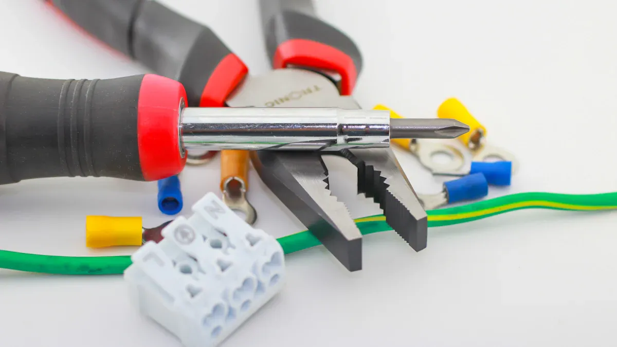
You can install cold-pressed terminal blocks with easy tools. Use a screwdriver to tighten screws. Use a wire stripper to get wires ready. A multimeter helps you check the connection. Put the wire connector into the terminal. Use a wrench to make it tight. Cold-pressed terminals give a strong connection. The process is reliable and lowers mistakes.
| Tool Type | Purpose |
|---|---|
| Screwdrivers | Tighten screws on terminal blocks |
| Wire Strippers | Get wires ready for connection |
| Multimeters | Check electrical connections |
| Cold Pressed Terminals | Make sure connections are strong |
Follow these steps for good results:
- Put the wire connector into the terminal.
- Use a wrench to make the terminal tight.
Some mistakes can cause problems. If you strip the wire too short, it may not connect well. Loose cores make the connection weak. If you put the cable too deep, it can hurt the terminal. Avoid these mistakes by following the instructions.
| Common Mistake | Description | Solution |
|---|---|---|
| Stripping length is too short | Cable may not go in all the way. | Strip the wire to the right length. |
| Loose core | Connection is weak and carries less current. | Fix the cables and make sure the crimp is right. |
| Cable inserted too deep | Can hurt the terminal and lower contact. | Do not push too hard and adjust the stop. |
⚡ Note: Always use the right tool and follow the steps to avoid mistakes.
Maintenance
You need to check cold-pressed terminal blocks often. Test the pulling force to see if the terminals hold wires tight. Every few months, test for rust, especially in wet places. Check the insulation to see if it can handle heat. These steps help you find problems early and keep connections strong.
| Maintenance Procedure | Description |
|---|---|
| Tensile testing | Check if the terminal holds the wire tight enough. |
| Environmental adaptability testing | Test for rust every few months in salty places. |
| Insulation material temperature resistance | Make sure insulation can handle high heat. |
You can do these steps for basic care:
- Check the terminals and wires for quality.
- Put the terminals on the ground wire.
- Put the wires into the terminal slots.
- Use a cold pressing tool to press the terminals tight.
🔍 Tip: Regular checks and tests help stop failures and keep your system safe.
Cold-pressed terminal blocks help you connect wires safely. They make your electrical work strong and secure. You can install them easily. They work well for many jobs. There are different types for different needs. When you pick, set up, and check them, your system stays safe. Always use the tips from this guide. If you are not sure, ask an expert for help.
Remember, taking care and making smart choices keeps your electrical work safe.
FAQ
What is the main difference between cold-pressed terminal blocks and regular terminal blocks?
Cold-pressed terminal blocks do not need heat or solder. You connect wires by pressing or tightening. Regular terminal blocks may need soldering or welding. Cold-pressed types save time and lower the risk of heat damage.
Can you reuse cold-pressed terminal blocks?
You can reuse some cold-pressed terminal blocks if they stay in good shape. Always check for damage or wear before using them again. If you see rust or loose parts, use a new block for safety.
How do you know which size terminal block to use?
Check your wire’s thickness and the current it carries. Match these to the block’s size and rating. Most blocks have clear labels. Using the right size keeps your connection safe and strong.
Are cold-pressed terminal blocks safe for outdoor use?
Some cold-pressed terminal blocks work outdoors. Look for blocks with weatherproof or waterproof ratings. These blocks resist rain, dust, and sun. Always read the product label before using them outside.
What tools do you need to install cold-pressed terminal blocks?
You need a wire stripper, a screwdriver, and sometimes a wrench. A multimeter helps you check your work. Using the right tools makes your connection strong and safe.
🛠️ Tip: Always follow the instructions from the manufacturer for best results.
See also
The difference between terminal blocks and cold-pressed terminals
Top 7 Terminal Block Brands Every Engineer Should Consider
Quick Guide to Common Terminal Blocks in Industrial Automation
How to Pick the Ideal Terminal Block for Your Project
A Complete Guide to Common Specifications of Terminal Blocks