
Wire + ferrule + clamp
Match conductor cross-section and strand class, ferrule barrel and collar, strip length, crimp profile, and terminal data.

Terminal blocks and crimp terminals solve different parts of a wiring problem, and many control panels use both. Start with the receiving interface and service plan. Then approve the exact wire, terminal or ferrule, tool, clamp or mating part, rating, environment, and documents as one connection system.
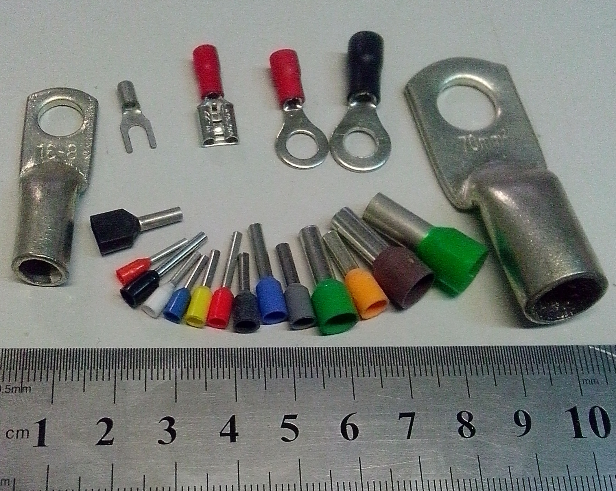
A terminal block provides one or more supported connection points. Depending on its design, it can join conductors, distribute a potential, provide test or disconnect functions, or make a protective-conductor connection. It also supports marking and organized field wiring.
A crimp terminal is attached to a conductor by controlled compression. Common forms include ring and fork terminals, cable lugs, quick-connect receptacles, pin contacts, butt splices, and wire-end ferrules. Some sourcing catalogs call these cold-pressed terminals, but that term covers several different products.
Choose a terminal block when you need an organized connection interface. Choose a crimp terminal when the receiving part is a stud, tab, connector housing, splice, or other interface made for that exact terminal. Use both when the approved design needs a prepared wire end plus terminal-block organization.
For product families, review the SENTOP terminal block range and cold-pressed terminal range.
A wire-end ferrule is crimped onto a fine-stranded conductor. It is then inserted into a compatible clamp. The ferrule does not replace the terminal block, and it is not suitable for every clamp.

Some screw, spring, or push-in terminals accept ferruled conductors. Some also accept fine-stranded copper directly. A ferrule can change the outside shape and the permitted conductor range. The terminal manufacturer must state whether the combination is accepted.
Match conductor cross-section and strand class, ferrule barrel and collar, strip length, crimp profile, and terminal data.
Never assume two wires, a twin ferrule, or a different lug is allowed because it appears to fit.
Phoenix Contact says flexible copper wire does not always need a ferrule. The allowed wire preparation depends on the connection type and product instructions.[8]
A DIN-rail block, ring lug, connector contact, and ferrule do not perform the same job. First state what must connect to what.
| Connection option | Best starting role | Main advantages | Main checks before approval | Common wrong assumption |
|---|---|---|---|---|
| DIN-rail through or distribution terminal block | Organized field-to-panel junction, distribution, marking, commoning, testing, or disconnect where the selected function is provided. | Accessible wiring interface; modular accessories; clear circuit identification; easier conductor replacement. | Exact conductor range and type, current and voltage data, ambient and grouping, connection technology, jumpers, end plates, rail, marking, and approval file. | Every block accepts several wires or every accessory in the same pitch family. |
| Crimp ring or fork terminal / cable lug | Conductor-to-stud or bolted equipment terminal. | Defined tongue or stud interface; useful for power devices, busbars, grounding points, and equipment studs when specified. | Conductor metal, size and strand class; barrel; stud hole and tongue; material/plating; matched die and tool; crimp dimensions; torque; cover and strain relief. | Any lug that fits the stud is electrically and mechanically compatible. |
| Crimp contact in a plug housing | Separable wire-to-wire or wire-to-board connector. | Compact harness interface; locking and polarization can be built into the full connector system. | Contact, housing, header, seal, wire and insulation range, crimp tool, insertion and retention, keying, mating cycles, rating, environment, and approval. | A loose contact alone is a complete connector or is automatically sealed. |
| Crimp butt splice or wire connector | Inline conductor splice when the exact product and installation method permit it. | Compact permanent splice; insulated or sealed versions exist for defined applications. | Wire material and range, one or more conductors per end, barrel and insulation, tool, crimp position, sealing process, enclosure, environment, and code category. | Crimp terminals cannot join wires, or every ordinary crimp splice is waterproof. |
| Wire-end ferrule | Preparing a fine-stranded conductor end for a compatible clamp. | Contains strands and can support repeatable insertion when the clamp manufacturer permits it. | Cross-section, single or twin form, barrel and collar, strip length, crimp profile, tool, finished dimensions, and terminal acceptance. | A ferrule is a junction device or is required on every stranded wire. |
No fixed current cutoff separates the two categories. High-current spring terminal blocks and large stud blocks exist, while crimp contacts and lugs cover many different current levels. Use the exact product rating, wire, ambient, approval system, short-circuit conditions where applicable, and end-equipment rules.[9][10]
This order avoids the most common sourcing error: choosing a familiar part first and forcing the wire, tool, panel, or certification to fit later.
Is it a junction or power split? Do you need test, disconnect, ground, stud, quick-connect, splice, or a plug?
The job narrows the product family.Material, cross-section or AWG, solid or strand class, insulation size, temperature class, and conductors per point.
Nominal wire size is not the full input.Clamp technology, stud diameter, tongue width, tab size, connector cavity, header, or splice arrangement.
Geometry must be documented.Check current, voltage, heat rise, ambient heat, grouped wires, spacing, duty, protection, and any short-circuit data.
Keep IEC and UL data in separate columns.Strip length, torque or crimp specification, die, applicator, insertion, inspection, pull test, and production records.
No universal torque or crimp setting exists.For a broader component workflow, use the SENTOP terminal block selection guide. For conductor-to-stud decisions, continue with the cold-press terminal guide.
The same connection can perform well in one assembly and fail in another. Mounting, tooling, wire support, access, housing, contamination, and maintenance instructions all matter.

They can make circuits easier to label, test, share, isolate, and repair. The chosen block and panel layout must support each task.
A lug or contact is useful when the equipment provides a stud, tab, or housing. Replacement may require the correct terminal and crimp tooling.
Qualified spring-pressure blocks can meet vibration tests. Stud and screw systems may use anti-loosening features. Crimp quality still depends on matched wire, tooling, locking, and strain relief.
For dust, water, chemicals, salt, or moisture, check the full connector or enclosure. Also check plating, wire, surface spacing, drainage, seals, and corrosion control.
Terminal-block installation and crimping need different controls. Neither should be reduced to “use a screwdriver” or “squeeze with a crimper.” The exact manufacturer instructions control the process.
Only qualified people should install or inspect these parts. Turn off power, lock and tag when needed, prove the circuit is dead, and follow the machine safety procedure.

Use the maker's stated wire and insulation range. Match the die or applicator, tool setting, strip length, and work instruction.
Check the cut and stripped wire. Check wire position, crimp height, bellmouth, conductor brush, and tool condition when the work instruction calls for them.
Set clear visual and size checks. Add pull tests, sampling, records, tool checks, lot control, and corrective action when the quality plan requires them.
Molex and TE both treat crimp quality as a system of terminal, wire, tooling, setup, inspection, and production control. A generic hand-tool squeeze cannot replace the exact application specification.[6][7]
Standards set test and construction frameworks. They do not make all products interchangeable or prove suitability in every finished machine. Check the exact order number, approval file, conductor, use group, mounting, accessories, and conditions of acceptability.
Covers support-mounted screw or screwless terminal blocks for industrial or similar use within its stated copper-conductor and voltage scope. Protective-conductor blocks have a separate part, IEC 60947-7-2.
View the official IEC scopeCovers defined crimp joints in electrical and electronic equipment. It applies to suitable crimp barrels and stated wire ranges. It is not one approval for every cable lug or finished product.
View the official IEC scopeTerminal blocks, wire connectors and lugs, quick-connect terminals, and ferrules follow different UL standards or categories. Verify the exact UL file and end-use conditions.
Review UL connector categoriesSets work and acceptance rules for cable and wire harnesses. It helps control the process. It does not replace the terminal maker's work instruction.
See the IPC releaseThese examples are starting points. The final design still needs data for the exact part and tests in the finished machine.
DIN-rail blocks can separate field wiring from internal control wiring, add labels, common potentials, and provide test or disconnect functions. Ferrules or ring/fork terminals may be used only where the exact clamp or stud permits them.
Often: block + approved wire preparationIf the device provides a stud or bolted pad, select a listed or certified lug for the conductor and stud. Then follow the lug crimp process and equipment torque instructions. Do not add an intermediate block unless the architecture needs it.
Often: ring lug or cable lugA plug housing and header can support a separable harness. Approve the complete contact, housing, seal, lock, header, wire, tool, keying, mating, and environment. A bare crimp contact is not a complete connector.
Often: contact + housing + headerA documented butt splice or wire connector may be suitable. Verify conductor count, material, wire range, tool, insulation or sealing method, enclosure, access, temperature, and the project code. Do not reuse a ring or fork terminal as a splice.
Often: approved splice systemDo not choose from the words “spring,” “screw,” or “crimp” alone. Ask for vibration and shock test data. Then test the real mount, wire route, lock, cable support, wire mass, and work cycle.
Winner depends on exact systemA crimp contact normally enters a compatible housing that mates with a PCB header. A PCB terminal block can accept field wiring directly. Press-fit and solder termination are separate product technologies; never solder a crimped contact unless its maker says to.
Choose wire-to-board interface firstSENTOP's control cabinet wiring components page helps place the connection inside the full panel BOM. Equipment manufacturers can also use the equipment manufacturer support path.
There is no reliable rule that a crimp terminal is always smaller or cheaper, or that a terminal block always saves more over its life. Compare one real architecture against another.
Include the block or terminal, housings, headers, rails, end stops, end plates, markers, jumpers, covers, seals, lugs, fasteners, and strain relief.
Include wire setup and crimp or torque tools. Add applicators, tool checks, inspection, samples, pull tests, labels, training, rework, and records.
Include access, repair tools, spare parts, wiring changes, and downtime. Add documents, lead time, MOQ, packing, approvals, and change control.
Space must be measured from drawings. Compare the installed connection, wire bend, tool approach, enclosure, rail, mating clearance, and service zone. Do not use a generic “terminal blocks are 60–70% larger” claim.
Each mistake removes one part of the real system.
Better check: map every interface. A panel may need blocks, ferrules, ring lugs, and plug contacts in different places.
Better check: use the exact product rating, wire, ambient heat, grouped-wire rules, approval data, protection, and machine rules.
Better check: validate the complete connector or lug interface, housing, lock, seal, wire support, and test evidence.
Better check: match terminal, conductor, applicator or die, tool setting, crimp specification, inspection, and test plan.
Better check: verify the clamp accepts that ferrule form and finished size. Some terminals accept fine-stranded wire directly.
Better check: wire, barrel, tongue, stud, metal, plating, tool, torque, heat rating, and approval must all match.
Better check: use the exact product and equipment instructions. Retighten only when those instructions require it.
Better check: compare the full BOM, tooling, labor, quality control, space, service, documents, supply, and downtime.
SENTOP supports parts around your panel and project. Send a drawing, photo, old code, sample, BOM, or device terminal detail. We can compare a terminal-block layout, a crimp-terminal layout, or an approved mix of both.
Use these answers to narrow the layout. The final choice comes from the exact data sheet, work instruction, approval file, tool, and assembly test.
A terminal block is a supported interface for joining, distributing, testing, disconnecting, grounding, or organizing conductors, depending on its design. A crimp terminal is compressed onto a conductor and then mates with a stud, tab, housing, clamp, or splice interface.
In many sourcing catalogs, “cold-pressed terminal” is used for crimped ring, fork, pin, blade, quick-connect, ferrule, or splice products. In engineering documents, use the specific product name because these items have different functions and standards.
Yes, when the exact terminal block is designed and documented for that prepared conductor. Examples include a ferrule in a compatible clamp or a ring or fork terminal on a compatible stud or screw interface. Fit alone is not approval.
No. Some terminals accept fine-stranded copper directly, while others permit or require specific ferrules. Follow the exact product data for conductor class, cross-section, strip length, ferrule dimensions, and crimp profile.
There is no universal winner. Qualified spring terminal blocks, screw or stud systems with suitable locking, and well-made crimp connections can all be designed for vibration. Validate the complete mounted assembly, wire support, strain relief, locking, and test evidence.
Neither group has one current limit. High-current blocks, stud blocks, cable lugs, and crimp contacts cover many ranges. Check the exact current and heat data, wire, mounting, protection, approval terms, and machine rules.
No. Compare the complete BOM, housings, rails and accessories, wire-bend and tool space, crimp or torque tooling, labor, inspection, service, documents, order volume, and downtime. The result changes by architecture and production scale.
Send the connection job, wire metal and size, strand class, mating part, current, voltage, environment, mounting, service need, and target approvals. Add a drawing or photo, quantity, destination, and required documents. Include the old part number or sample when available.
Send the connection job, wire, mating part, ratings, environment, mounting, target approval, volume, destination, and document needs. SENTOP can help plan the next component match.
