Core Products: Terminal Blocks, Transfer Switches & Digital Panel Meters Supporting Electrical Categories | OEM/ODM | Project-Based Quotation
Products
Industries
Resources
Electrical Tools
Company
Start a Conversation
Share a model, BOM, product photo or application requirement for review.
Technician reconfiguring labeled control wires inside a SCADA cabinet
Interface Architecture Guide for Panel Builders and OEMs

Terminal Block or Connector: Which One Fits Your Project?

Choose a terminal block when you need a mounted, point-by-point wiring interface with clear labeling and service access. Choose a separable plug-and-receptacle connector when you need fast module replacement, a factory-built cable harness, blind mating, keying, or a defined data interface. Many machines use both.

InterfaceFixed field wiring, module, cable, board, or equipment
ServicePoint access, replacement time, and mating cycles
DutyPower, signal, data, conductor, and temperature
EnvironmentMotion, vibration, sealing, EMC, and enclosure
Panel wiring often favors point-by-point service access. Photo: MTA Capital Construction Mega Projects / Wikimedia Commons, CC BY 2.0. Layout crop only.
Quick Decision

Choose the interface job first, then the product family

A terminal block is itself a type of electrical connector. In this guide, “connector” means a separable plug-and-receptacle interface. “Terminal block” means a mounted wire-termination point used to organize or distribute panel and equipment wiring.

Review a BOM
Favor a terminal block when

Technicians service one circuit at a time

The equipment needs visible wire labels, field wiring, PE or distribution functions, test access, disconnect points, rail accessories, or easy conductor replacement.

Best fit: a controlled, mounted wiring interface.
Favor a connector when

A complete module or harness must separate

The design needs a defined plug and receptacle, fast replacement, factory-built harnesses, coding, latching, blind mating, shielding, or environmental sealing.

Best fit: a controlled, separable interface.
Use a hybrid when

Field wires meet a replaceable module

A pluggable terminal block can accept field conductors in one half while the equipment or PCB uses a separable header. It combines features of both architectures.

Best fit: field wiring plus module exchange.
Do not decide yet when

Ratings or service conditions are incomplete

Pause when voltage, current, conductor, loaded contacts, mating cycles, strain relief, motion, temperature, fault duty, IP conditions, EMC, or approval scope is unknown.

Missing inputs can change the architecture.
The shortest useful rule

Use terminal blocks for fixed, organized, individually serviceable wiring. Use separable connectors for a defined plug-and-receptacle break point. Use both when the cabinet needs field wiring on one side and quick module replacement on the other.

For cabinet projects, also review control cabinet wiring components and the control panel wiring guide. These pages help connect the interface choice to the wider BOM and assembly process.

What You Are Actually Comparing

Termination method and interface type are different decisions

A connector can use crimp, solder, insulation-displacement, screw, spring, or another termination behind its mating face. A terminal block can use screw, spring, push-in, stud, tab, or PCB pins. Do not use the termination method as the product category.

Two industrial power terminal blocks designed for DIN-rail mounting
DIN-rail power terminals provide mounted, individually serviceable wire points. Photo: Dmitry G / Wikimedia Commons, CC BY-SA 3.0. Layout crop only.
Mounted terminal block

The wire lands on a supported insulating body

The block mounts to a rail, panel, PCB, or other support. Conductors terminate at defined clamping points. Accessories can add grouping, bridging, marking, test access, separation, grounding, fusing, or disconnect functions.

  • Good at: field wiring, circuit-by-circuit labels, modular rail building, testing, and individual conductor service.
  • Needs: conductor preparation, correct insertion or torque, end plates, bridges, rail support, spacing, and enclosure review.
  • Not always permanent: wires can be removed, and some terminal systems are pluggable.
  • Not automatically compact: count pitch, levels, accessories, wire bend, driver, and service space.
Review SENTOP terminal block options →
Mated 16-pin M23 circular plug and socket connector on a white background
A threaded M23 connector forms a keyed, separable equipment interface. Photo: Phiarc / Wikimedia Commons, CC BY-SA 4.0. Layout crop only.
Separable connector

A plug and receptacle create a repeatable mating face

The interface may be wire-to-wire, wire-to-board, board-to-board, panel feedthrough, circular, rectangular, coaxial, fiber, or another form. Contacts and housings must be compatible as one connector system.

  • Good at: module replacement, harness production, keying, coding, latching, blind mating, shielding, or sealed interfaces.
  • Needs: both mating halves, approved contacts, tooling, cable preparation, backshell or seal, strain relief, and mating instructions.
  • Not a switch by default: do not mate or unmate under load unless the manufacturer explicitly permits it.
  • Not always frequent-use: mating durability belongs to the exact connector series.
Review plug-in and PCB terminal block options →
Classification correction

Terminal block versus connector is an operating comparison, not a strict family tree

Pluggable terminal blocks sit between the two. They keep a terminal-style field-wiring side and add a separable header or plug. This can reduce module replacement time while keeping the conductor termination inside a controlled product family.

Five Interface Questions

Map the physical break point before comparing catalogs

The best interface becomes clearer when you define what separates, who installs it, and how it is serviced.

01 / BREAK POINT

What must separate?

One conductor, a cable, a harness, a removable module, a PCB, a door, a field device, or an entire machine section.

Choose the separation unit first.
02 / INSTALLER

Who makes the joint?

Factory harness team, panel shop, field electrician, equipment technician, or end user. Tool and skill control can differ.

Match factory and field wiring rules.
03 / SERVICE

How often is it opened?

Never after assembly, during planned service, for module exchange, for testing, or for repeated normal operation.

Use the stated mating durability.
04 / CIRCUIT

What passes through?

Power, PE, analog, digital, data, RF, motor, sensor, actuator, shield, mixed signal, or safety-related circuits.

Signal and protection needs differ.
05 / EXPOSURE

What reaches the interface?

Motion, pull, cable mass, vibration, shock, dust, water, condensation, chemicals, temperature, corrosion, EMI, or public access.

Design strain relief and enclosure together.
DefineSeparation unitWire, cable, module, PCB, or equipment
AssignFactory or fieldInstaller, tooling, inspection, and service owner
RateElectrical dutyPower, signal, data, conductor, thermal, and fault
ProtectMechanical interfaceLocking, coding, strain relief, enclosure, and motion
ReleaseComplete systemExact parts, work instructions, tests, and approvals
Side-by-Side Comparison

Compare the complete interface, not category stereotypes

The tendencies below help you choose an architecture. They do not rate a product. Exact terminal blocks and connectors overlap in current, voltage, size, vibration, sealing, service life, and cost.

Open the Selection Guide
Decision pointMounted terminal blockSeparable plug/receptacle connector
Primary interfaceIndividual conductors land on mounted points. Useful for field and panel wiring.Two matched halves create a designed break point. Useful for cables, modules, or equipment sections.
Service unitOne conductor, circuit, fuse, disconnect, bridge, or test point can often be accessed independently.A whole cable or multipole interface can be released together, subject to safe isolation and mating instructions.
Wiring processStrip and insert each conductor using the exact screw, spring, push-in, stud, or other terminal method.Terminate contacts or conductors, assemble housing/seals/backshell, inspect, and mate using the specified lock and coding.
Mating cyclesWire re-termination endurance is model- and method-specific; terminal service is not a universal cycle rating.Use the exact series' stated mating durability and conditions. A separable interface is not automatically frequent-use.
Live separationDe-energize before conductor work unless the complete equipment and procedure explicitly permit otherwise.Do not mate or unmate energized or under load unless the connector is expressly rated for that duty.
Vibration and motionCheck clamp, wire support, rail mounting, accessories, conductor, and tested vibration/shock profile.Check contact retention, mating lock, secondary lock, backshell, cable mass, strain relief, flex point, and tested profile.
High-speed or RFGeneric blocks are rarely controlled-impedance interfaces. A dedicated terminal or shield system may work for stated signals.Dedicated data or RF connectors can control geometry, impedance, return path, shielding, and coupling when specified.
Environmental protectionA bare rail block normally relies on the equipment enclosure. Verify pollution, condensation, corrosion, and temperature.An IP rating may apply only when fully mated, sealed, and assembled with the specified cable and accessories.
SpaceCount pitch, levels, end plates, bridges, markers, driver/actuation access, wire bend, and service clearance.Count both halves, latch or coupling, backshell, bend radius, mating stroke, release access, and panel cutout.
CostCount blocks, accessories, rail, tools, assembly time, inspection, cabinet space, and service.Count both halves, contacts, seals, backshell, tooling, harness labor, testing, spares, and service time.
Best evidenceExact data sheet, conductor table, drawing, accessories, work instruction, tests, certification record, and end-use conditions.Exact matched halves, contacts, cable range, tooling, assembly spec, derating, mating durability, IP conditions, tests, and certification record.

Important: a standard's scope is not a product rating. The selected catalog number must carry the required ratings and approvals for the intended installation.

Mating, Movement, and Service

A removable interface needs more than a plug shape

When a cable moves or a module is replaced, the mechanical path matters as much as the electrical contact. Route motion through a connector and cable-management system designed for that duty. Do not let repeated flexing or tensile load reach the conductor termination.

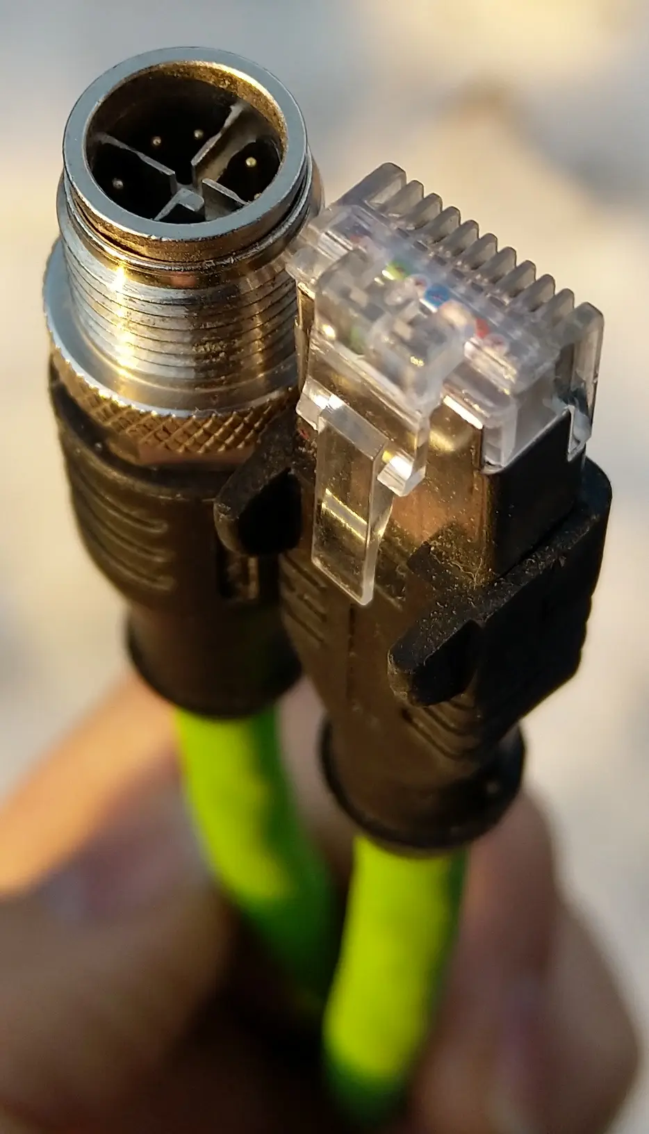
M12 X-coded and 8P8C Ethernet cable connectors showing different locking designs

Locking method and service cycles belong to the exact connector

This image compares a threaded M12 interface with a latch-based 8P8C plug. It illustrates different retention methods, not a universal durability ranking. Check mating cycles, latch wear, coupling torque if stated, cable flex, pull load, seal condition, inspection, and replacement criteria for the chosen series.

Photo: Anordal / Wikimedia Commons, CC BY-SA 4.0.
Retention

How does it stay mated?

Friction, latch, screw coupling, bayonet, lever, secondary lock, panel hardware, or another method. Verify the fully locked indication and release access.

Strain relief

Where does cable force go?

Control pull, bending, torsion, cable mass, repeated flex, and vibration before they reach the contact or wire termination.

Replacement

What is the service unit?

Define whether technicians replace a contact, plug, cable assembly, module, header, terminal, or complete harness and how errors are prevented.

Never assume a connector is a load-break device.

Many connectors have no breaking capacity and are not intended to be engaged or disengaged during normal use while live or under load. De-energize, isolate stored energy, verify absence of voltage, and follow the equipment and connector instructions unless the exact product is explicitly rated and applied for live or load operation.

Power, Control, and Data

Signal type can change the whole interface geometry

Do not reduce the decision to “terminal block for power, connector for data.” Both families cover many duties. High-speed and RF circuits need a defined electrical channel, not simply a shielded housing.

POWER

Check thermal and fault duty

Compare working voltage, current, conductor, contact loading, ambient, temperature rise, derating, fault current, protection, touch safety, spacing, and end-product conditions.

PROTECTIVE EARTH

Keep the bonding path defined

Use products and mounting methods accepted for PE. Verify continuity, conductor, rail or chassis interface, markings, accessories, and assembly tests.

ANALOG & SENSOR

Control noise and test access

Consider shield termination, separation, reference path, contact material, thermocouple or low-level signal needs, disconnect/test functions, and calibration architecture.

DIGITAL DATA

Use the specified channel

Check protocol, data rate, bandwidth, impedance, return loss, insertion loss, crosstalk, coding, shielding, cable, topology, and EMC tests.

RF / COAX

Preserve controlled impedance

Use a coaxial or RF interface designed for frequency, impedance, connector gender, cable, power, environmental duty, and mating control.

MIXED POWER & SIGNAL

Coordinate contacts and separation

Verify pin assignment, PE sequencing, creepage, clearance, shielding, keying, contact loading, thermal interaction, and fault isolation within the same system.

Nine Project Checks

What to verify before the interface enters the BOM

Use this list for terminal blocks, separable connectors, and pluggable terminal systems. It turns a product-category preference into a controlled design decision.

01

Physical break point

Define wire, cable, harness, module, board, field device, door, enclosure, or machine section and the direction of assembly.

02

Connection frequency

State initial assembly, planned service, module exchange, testing, or repeated use. Use exact mating or re-termination durability.

03

Electrical duty

List AC/DC voltage, current, frequency, impulse, fault data, duty, loaded contacts, ambient, temperature rise, and protection.

04

Conductor and cable

Give copper/aluminum permission, AWG or mm², class, insulation diameter, strip length, ferrule/contact, cable OD, shield, and bend radius.

05

Poles and coding

Count circuits, PE, neutral, shields, spare ways, branches, bridges, test points, contact sequencing, keying, coding, and mis-mating risk.

06

Space and access

Measure pitch, levels, rail/PCB area, cutout, mating stroke, latch/coupling access, wire bend, backshell, tool clearance, and service reach.

07

Movement and environment

Match vibration, shock, cable pull, flex, strain relief, temperature, humidity, condensation, dust, water, chemicals, salt, corrosion, and UV.

08

Assembly process

Define strip, crimp, solder, insertion, torque, actuation, seal, backshell, lock, inspection, pull check, test, marking, and rework.

09

Exact evidence

Verify matched part numbers, contacts, accessories, data sheets, drawings, derating, test reports, certification records, end-use conditions, and change control.

Installed cost: compare piece parts, both connector halves, contacts, terminal accessories, tooling, harness or panel labor, inspection, cabinet space, spares, downtime, and production volume. Neither category is universally cheaper.

Prototype the workflow, not only the electrical path

Build a short sample strip or cable assembly with the real wire, tool, labels, enclosure space, and technician. Time the complete task: preparation, termination, inspection, mounting, mating, release, and correction. Record errors and access problems. This small trial can reveal whether a fast connector step creates extra harness work, or whether a simple terminal needs more cabinet space than expected.

Standards and Responsibility

Terminal blocks and component connectors follow different standard paths

IEC 60947-7-1:2025 covers industrial terminal blocks for copper conductors within its stated scope. IEC 61984:2008 provides safety requirements and tests for connectors within its stated scope. In North America, UL lists UL 1059 for terminal blocks and UL 1977 for component connectors.[1][2]

Meeting a component standard does not, by itself, prove suitability in finished equipment. Check the exact component record, ratings, conditions of use, matched system parts, and the end-product standard.

SENTOP responsibility boundary: SENTOP can support terminal-block model matching, samples, drawings, available documents, accessories, labels, packing, and mixed-BOM review. The responsible equipment team selects the interface architecture and approves electrical duty, signal performance, protection, insulation, thermal design, motion, enclosure, EMC, functional safety, assembly, testing, installation, and market compliance.
Review SENTOP standards and certificate support →
IEC 60947-7-1:2025

Industrial terminal blocks for copper conductors, fixed to a support, within the standard's voltage and conductor scope.

Official IEC scope
IEC 61984:2008

Connector safety requirements and tests within its scope. Product detail specifications and manufacturer data still govern the exact interface.

Official IEC scope
UL 1059 vs UL 1977

UL distinguishes terminal-block assemblies from component connectors used for data, signal, control, and power applications.

Official UL overview
IEC 60512-1:2018

Basic connector test and measurement framework. The chosen product or detail specification defines the relevant tests and severity.

Official IEC scope
Prepare a Useful Interface Enquiry

Send the break point, circuit, and service plan

A model, photo, drawing, sample, cable schedule, or BOM helps SENTOP compare mounted and pluggable terminal options without guessing. Include the information below.

ArchitecturePhysical break pointField wire, cable, harness, module, PCB, door, field device, or equipment section; fixed or separable.
CircuitFunction and ratingsPower, PE, control, sensor, data or RF; AC/DC voltage, current, frequency, fault, thermal, signal, and shielding needs.
ConductorWire and cableMaterial, AWG or mm², class, insulation, ferrule/contact, cable OD, shield, bend radius, branches, and poles.
MechanicalMounting and serviceDIN rail, PCB, panel or cable mounting; dimensions, mating direction, cycles, locking, keying, tool access, replacement, and strain relief.
EnvironmentExposure and enclosureTemperature, vibration, shock, motion, pull, dust, water, condensation, chemicals, corrosion, UV, public access, and IP conditions.
ProjectEvidence and supplyExisting model/photo/drawing/BOM, target market, standards, documents, sample, quantity, labels, packing, destination, and delivery plan.

Production support

Control samples and variants

Use OEM and ODM support for drawings, labels, samples, approved changes, packaging, and project quantities.

Terminal Block vs Connector FAQ

Short answers for panel teams and equipment makers

Use these answers to frame the architecture. The exact model, mating system, conductor, environment, equipment, and evidence still decide suitability.

What is the main difference between a terminal block and a connector?

A terminal block is a type of connector, but it usually provides mounted, point-by-point wire terminations for panel or equipment wiring. In this comparison, “connector” means a separable plug-and-receptacle interface that disconnects a cable, harness, module, board, or equipment section as a unit.

When should I choose a terminal block?

Choose a terminal block when the design needs field wiring, clear circuit labels, individual conductor service, rail accessories, PE or distribution functions, fuse or disconnect points, testing, or easy point-by-point changes. Verify the exact model, conductor, ratings, mounting, environment, accessories, and end-use conditions.

When should I choose a separable connector?

Choose a separable connector when a cable, harness, module, board, door, or equipment section must disconnect as one controlled interface. It can add keying, locking, blind mating, shielding, or sealing. Check both mating halves, contacts, tooling, cable, cycles, strain relief, and approval scope.

Can terminal blocks and connectors be used together?

Yes. Many systems terminate field wires on terminal blocks, then use a separable connector for a replaceable module or cable harness. Pluggable terminal blocks combine both ideas. Control the pinout, ratings, coding, accessories, spacing, work instructions, and certification across the complete interface.

Can I unplug a connector while the equipment is powered?

Not unless the exact connector and equipment are expressly rated and applied for that operation. Many component connectors have no breaking capacity. De-energize, isolate stored energy, verify absence of voltage, and follow the manufacturer and equipment instructions before mating or unmating.

Are connectors always better for vibration?

No. Compare the exact contact system, mating lock, secondary lock, cable mass, backshell, strain relief, mounting, conductor, and tested vibration and shock profile. Terminal blocks also have vibration-capable designs. Product category alone does not prove performance.

Does an IP rating make a connector or terminal block suitable outdoors?

No. A bare rail terminal normally relies on its enclosure. A connector's IP rating may apply only when fully mated, sealed, and assembled with the specified cable and accessories. Also check UV, condensation, corrosion, temperature, salt, chemicals, cable entries, and the complete equipment rating.

What should I send for terminal block or pluggable interface matching?

Send the break point; existing model, photo, drawing, sample, cable schedule, or BOM; circuit function; voltage, current, fault, temperature, and signal data; conductor and cable; poles; dimensions; mounting; cycles; locking; environment; target market; documents; quantity; labels; packing; destination; and delivery plan.

Official technical sources used for this guide

  1. IEC 60947-7-1:2025. Official scope for industrial terminal blocks with screw-type or screwless-type clamping units for copper conductors.
  2. IEC 61984:2008. Safety requirements and tests for connectors within its stated scope.
  3. IEC 60512-1:2018. Basic connector and contact test and measurement framework.
  4. UL Solutions — Connector certification services. Official distinction among UL 1059 terminal blocks, UL 1977 component connectors, wire connectors, quick-connect terminals, and cable assemblies.
  5. ANSI/UL 1059, Sixth Edition. Official terminal-block scope and end-product suitability boundary.
  6. UL 1977. Official component-connector scope for data, signal, control, and power applications.
  7. IEC 61076-3-119:2017. A connector detail-specification example stating that connectors without breaking capacity are not intended for normal mating or unmating while live or under load.
  8. Phoenix Contact — Pluggable terminal blocks. Official example of a hybrid interface that combines terminal wiring and plug-in separation.
  9. Phoenix Contact — Terminal block connection technologies. Official product-family overview and model-specific connection options.
  10. OSHA 29 CFR 1910.333. De-energization and verification requirements for work on exposed electrical parts.
Electrical Components Built Around Your Panel and Project

Have a module, cable, terminal, drawing, or BOM interface to review?

Send the break point, circuit duty, conductor and cable, poles, dimensions, mounting, mating plan, environment, target market, document needs, quantity, and destination. SENTOP can help match mounted or pluggable terminal options for your panel or equipment project.

滚动至顶部