

Handling electrical systems requires great caution. Even a small mistake can lead to serious injuries or damage. Prioritizing safety is essential to protect yourself and others.
This guide provides simple steps to safely dismantle RCCB (Residual Current Circuit Breaker). By carefully following these instructions, you can prevent accidents and complete the task with confidence.
Always remember: safety is the top priority when working with electricity.
Key Takeaways
- Always switch off the main power before doing electrical work. This stops electric shocks and keeps you safe.
- Use tools with insulated handles, like screwdrivers and pliers. These tools keep you safe from touching electricity by accident.
- Check for no electricity using a voltage tester. This step makes sure the RCCB is safe to touch.
- Work in a clean, dry, and bright area. Good lighting helps you see better and avoid mistakes.
- If you’re unsure or the RCCB looks broken, call an electrician. Experts make sure the work is safe and follows rules.
Safety Precautions for Safely Dismantling an RCCB
Turn off the main power supply
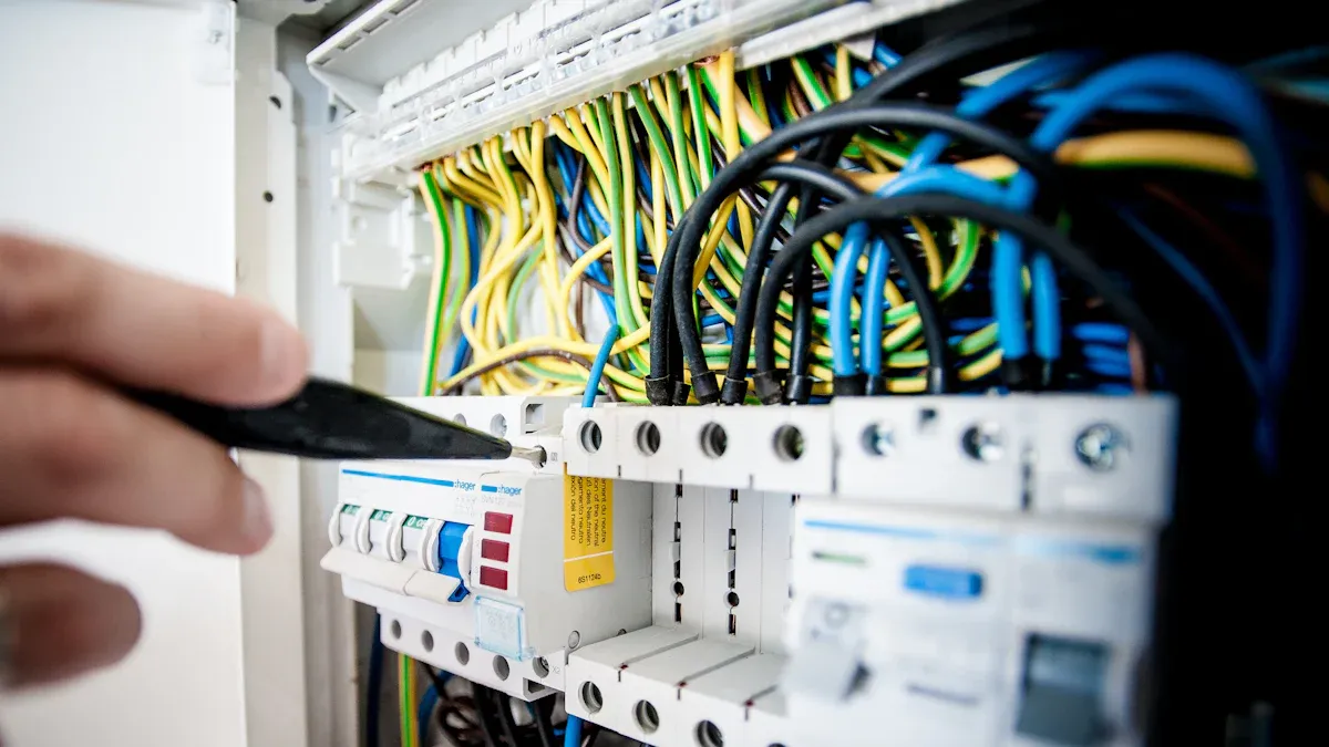
Make sure the main power is completely off. Find the main switch or breaker in the panel. Flip it to “off” to stop electricity flow. Mark the panel clearly to show the power is off. This helps others know not to turn it back on.
Tip: Check the switch again to avoid electric shocks.
Use appropriate Personal Protective Equipment (PPE)
Wear proper safety gear to stay protected. Use insulated gloves to keep your hands safe from shocks. Wear safety goggles to shield your eyes from sparks or debris. If it’s loud, use ear protection to reduce noise.
Note: PPE is very important. It keeps you safe from harm.
Verify the absence of electrical current
After turning off the power, check for leftover electricity. Use a voltage tester or multimeter to confirm no current is present. Place the tester on the RCCB terminals and check the reading. If voltage is found, fix the issue before continuing.
Alert: Skipping this step can cause serious injuries. Always check first.
By following these steps, you can remove the RCCB safely. Each step lowers risks and makes the process easier.
Stand on a rubber mat or plywood for safety
When working with electricity, standing on a safe surface is key. A rubber mat or plywood keeps you insulated from the ground. This lowers the chance of electric shock if something goes wrong. Rubber blocks electricity because it does not conduct it easily. Plywood is less effective than rubber but still adds some protection.
Tip: Check the mat or plywood before using it. Make sure it is dry, clean, and not damaged.
These materials also help you stay steady while working. Losing balance or slipping can cause accidents with electrical parts. Place the mat or plywood on a flat area to keep it stable.
This step adds extra safety when removing RCCB units. It reduces the risk of electrical dangers during the process.
Keep your workspace bright and dry
Good lighting helps you see your work clearly. Poor light can cause mistakes, like connecting wires wrong or missing details. Use a flashlight or lamp if the area is too dark. Place the light so it does not create shadows on your work.
A dry workspace is just as important. Water and electricity are very dangerous together. Even a little water can increase the risk of shocks. Before starting, check for water or damp spots. Dry the area and tools completely.
Alert: Never work if the area is wet. If you see water near the panel, stop and fix the issue first.
A clean, dry, and bright workspace keeps you safe and helps you work better. These conditions are crucial for tasks like removing an RCCB.
Tools Needed to Remove an RCCB Safely
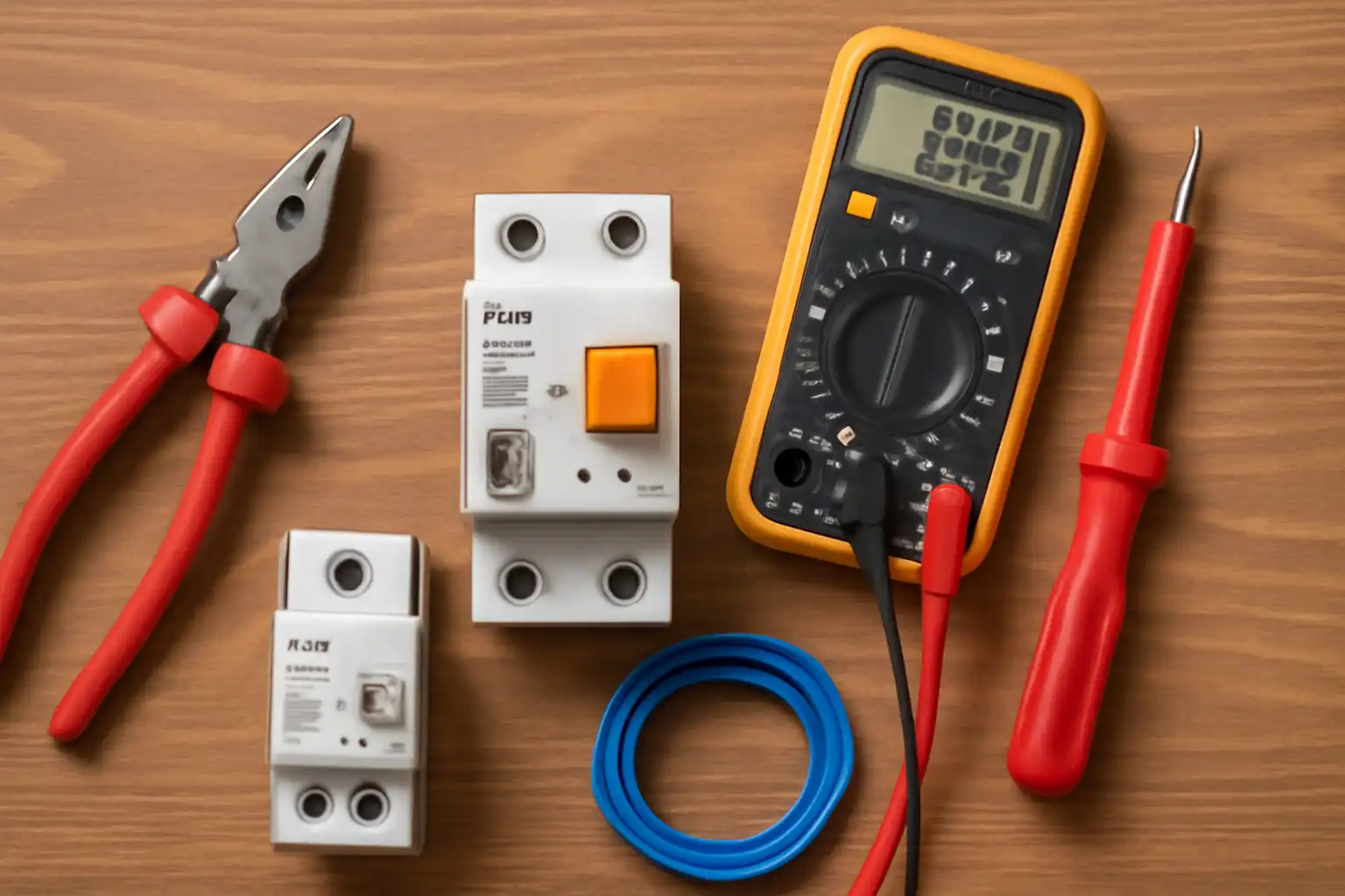
Having the right tools is very important for electrical work. Using the correct tools makes the job safer and easier. Below are the tools you need to safely remove an RCCB.
Insulated screwdriver set
You need an insulated screwdriver set for electrical tasks. These screwdrivers have special coatings that stop electric shocks. Use them to loosen or tighten screws on the RCCB safely. They protect you from touching live wires.
Why insulated tools are important:
- They stop accidental contact with electricity.
- They are necessary for safely removing RCCBs and other parts.
Pick good-quality insulated screwdrivers that meet safety rules. Spending a little more on these tools can prevent accidents.
Voltage tester or multimeter
Before starting, check if the RCCB has electricity. A voltage tester or multimeter helps you find live wires. Place it on the RCCB terminals to confirm the power is off.
Tip: Test the voltage tester on a live circuit first to ensure it works.
Using a voltage tester is not optional. It is a key step to avoid electric shocks.
Insulated pliers
Insulated pliers are also important for electrical work. They help you grip, twist, or cut wires safely. These pliers are made with materials that block electricity to protect you.
| Feature | What It Does |
|---|---|
| Dielectric Rating | Protects up to 1000V for safety. |
| Material | Made with fire-resistant materials. |
| Handle Design | Non-slip handles for a firm grip. |
| Temperature Range | Works between -20° to +70°C. |
| Safety Guard | Stops your hand from slipping onto metal. |
Using regular pliers can cause serious injuries. Insulated pliers are made to lower risks, so they are a must-have tool.
By using these tools, you can remove an RCCB safely and avoid accidents. Always use high-quality, insulated tools to stay safe.
Electrical tape
Electrical tape is a must-have for removing an RCCB safely. It covers exposed wires to stop accidental contact. This lowers the chance of electric shocks.
Choose good-quality, flame-resistant electrical tape. These tapes handle heat and last longer. Do not use regular tape because it cannot block electricity.
Tip: Keep electrical tape in your toolbox. It can also fix damaged wire coverings temporarily.
To use it, wrap the tape tightly around exposed wires. Make sure no metal is showing. Overlap the tape slightly to seal it well. This step keeps you safe during and after removing the RCCB.
Flashlight (if working in low-light conditions)
A flashlight is very helpful in dark areas. It helps you see clearly and avoid mistakes with wires or connections. Poor lighting can cause errors that lead to accidents.
Modern flashlights are brighter and safer. High-lumen flashlights, from 500 to 1,100 lumens, light up workspaces well. Some are made for risky areas, like places with flammable materials.
- Bright flashlights light up large areas.
- Special models are safer in dangerous environments.
- Small designs fit into tight spaces easily.
A study showed safer flashlights reduced fire risks during repairs. The FAA also says good lighting tools help prevent mistakes.
Alert: Check your flashlight’s battery before starting. A dead flashlight can stop your work.
Using a good flashlight makes working in dark spaces easier and safer. It’s a small tool that improves safety and accuracy.
Step-by-Step Guide to Safely Dismantle an RCCB
Turn off the main power supply and confirm it is off
Find the main power switch in the electrical panel. Flip it to “off” to stop electricity. Label the panel clearly to warn others not to turn it back on.
Check the power with a voltage tester or multimeter. Place the tester on the RCCB terminals to see if electricity is present. If no voltage is detected, you can move forward.
Tip: Always check the main switch twice. This step keeps you safe.
Test the RCCB for leftover current using a voltage tester
Even after turning off the power, some current may remain. Use a voltage tester to check for this. Place the tester on the RCCB terminals and read the results. If current is found, wait or call an expert for help.
Leftover current can be dangerous during removal. Testing ensures the RCCB is safe to touch.
Alert: Never skip this step. Leftover current can cause shocks.
Remove the conductor from the top of the RCCB
After confirming no current, focus on the wires at the top. Use insulated pliers to loosen and remove these wires. Hold the conductor firmly and pull it away from the terminal.
Check the wires for damage like exposed or frayed parts. Wrap damaged areas with electrical tape to avoid accidents.
Note: Be gentle with the wires. Damaged wires can cause problems later.
Follow these steps to safely remove the RCCB. Each step reduces risks and makes the process easier.
Unscrew the lower and upper terminals to detach the RCCB from the busbar
Start by finding the screws on the lower and upper terminals. These screws hold the RCCB to the busbar. Use an insulated screwdriver to loosen them. Turn the screwdriver to the left until the screws come out completely. This step disconnects the RCCB from the system.
Tip: Keep the screws in one spot. You might need them later for reinstalling or replacing the RCCB.
After removing the screws, gently pull the terminals off the busbar. Do not pull too hard, as it may break the terminals or busbar. Check the terminals for damage or rust. Fix any problems before moving forward.
Release the catch under the RCCB and pull the bottom part out
Most RCCBs have a small catch at the bottom. This catch locks the RCCB to the mounting rail. Look under the RCCB to find it. Use your fingers or an insulated tool to unlock the catch.
Once the catch is unlocked, tilt the bottom of the RCCB outward. This will free it from the mounting rail. Be careful not to move too quickly, as this could harm nearby parts.
Alert: If the catch is stuck, do not force it. Forcing it might break the RCCB or the rail. Check the manual or ask an expert for help instead.
Safely remove the RCCB and insulate exposed wires with electrical tape
With the catch unlocked and terminals detached, you can now remove the RCCB. Hold it firmly and lift it out of the panel. Place it on a safe surface like a rubber mat or wooden table. This prevents accidental contact with live parts.
Next, cover the exposed wires with electrical tape. Use strong, good-quality tape to wrap the ends of each wire. Make sure no metal is left uncovered. This step stops accidental shocks and keeps you safe.
Note: If you are installing a new RCCB right away, you can skip taping the wires. But always handle the wires carefully during installation.
By following these steps, you can remove an RCCB safely without risking injury or damaging the system.
When to Call a Professional for RCCB Removal
Taking out an RCCB can be hard if you don’t know much about electricity. Sometimes, it’s better to ask a professional for help. Below are times when calling an expert is the safest option.
If you don’t understand the electrical panel
Electrical panels can be confusing to figure out. Wires and parts may look alike, making it tough to pick the right ones. If you’re unsure, don’t guess. Guessing can cause shocks or damage the system.
Tip: Electricians know how to handle tricky setups. They can remove the RCCB safely without causing harm.
If the RCCB is broken or stuck
A damaged RCCB might have cracks, burns, or melted spots. A stuck RCCB can be hard to remove without breaking it or its rail. Forcing it out could make things worse or even start a fire.
Alert: Broken RCCBs are risky. Let an expert deal with them to stay safe.
If you don’t have the right tools or skills
Using tools that aren’t insulated can be dangerous. Regular screwdrivers or pliers won’t protect you from electricity. Without proper tools, you could get shocked or ruin the RCCB. Not knowing what to do can also lead to mistakes, like skipping safety steps.
Note: Experts bring the right tools and know-how. They make sure the job is done safely and correctly.
Knowing when to call a professional helps you stay safe. Safety should always come first.
If local rules need licensed electricians for electrical work
Some places require only licensed electricians to do electrical jobs, like removing an RCCB. These rules are made to keep you and your property safe. Licensed electricians are trained and certified to follow strict safety rules.
Tip: Check your area’s building codes or ask your utility company if a licensed electrician is needed.
Why Local Rules Are Important
Local governments create these rules to lower risks like fires, shocks, or system problems. People without training might skip important safety steps, causing danger. Hiring a licensed expert ensures the work meets legal and safety standards.
How to Know If You Need a Licensed Electrician
Here’s how to check if your area requires licensed electricians:
- Call your local government office: They can explain the rules for electrical work.
- Look at your homeowner’s insurance policy: Some policies only cover work done by licensed electricians.
- Ask an electrician: Most professionals know the rules in your area and can advise you.
Alert: Ignoring these rules can lead to fines or canceled insurance claims. Always check before starting any electrical work.
Why Hiring a Licensed Electrician Helps
Licensed electricians offer many benefits:
- They follow safety steps to avoid accidents.
- They have the right tools and skills to finish the job well.
- Their work often comes with a guarantee, giving you confidence.
Following local rules keeps you, your property, and others safe. Always focus on safety and follow the law when working with electrical systems.
Taking out an RCCB safely means following simple steps. First, turn off the main power and make sure it’s off. Use a voltage tester to check for leftover electricity. Remove the conductor, loosen the screws, and unlock the catch to take out the RCCB. Cover exposed wires with electrical tape to stay safe.
Safety Reminder: Always use insulated tools and work in a dry, bright space to prevent accidents.
If you’re unsure or face problems, call a licensed electrician. Experts follow strict rules, such as:
- Checking and fixing electrical parts often.
- Using clear safety guidelines for handling equipment.
- Keeping records of checks and repairs.
- Making sure all safety steps are followed.
Your safety is the most important. If unsure, let a professional do the work.
FAQ
What is an RCCB, and why is it important?
An RCCB, or Residual Current Circuit Breaker, keeps you safe. It stops electric shocks by detecting current leaks. When it finds a problem, it cuts off electricity. This prevents accidents and protects your electrical system.
Can I remove an RCCB without turning off the main power?
No, you must turn off the main power first. Working with live electricity is very dangerous. It can cause serious shocks or damage. Always cut the power before starting to stay safe.
How do I know if my RCCB is faulty?
A faulty RCCB might trip often for no reason. It may also fail to trip when tested. Press the “Test” button to check if it works. If it doesn’t trip, you might need to replace it.
Is it safe to reuse an old RCCB?
You can reuse an RCCB if it’s still in good shape. Check for cracks, burns, or other damage. Test it to make sure it works properly. If unsure, ask an expert to confirm it’s safe to use again.
What should I do if I accidentally touch an exposed wire?
Stop working right away and move away from the wire. If you feel a shock, see a doctor immediately. Cover the wire with electrical tape to make it safe. Always wear insulated gloves to avoid touching bare wires.
The following information may be of interest to you
How to safely remove circuit breakers from distribution boxes
What Are Residual Current Circuit Breakers and How Do They Work
Top 8 Residual Current Circuit Breaker Brands for Home Safety
How to Test Surge Protection Devices for Optimal Performance

Discover more from SENTOP Electrical Co., Ltd
Subscribe to get the latest posts sent to your email.
